2002 LAND ROVER DISCOVERY battery replacement
[x] Cancel search: battery replacementPage 1295 of 1672
PANEL REPAIRS
77-2-46 REPAIRS
'E' post closing assembly
In this procedure, the panel body side assembly, tail
door and 'E' post assembly are replaced in
conjunction with the 'E' post closing assembly.
Remove
1.Disconnect both battery leads, negative lead
first.
2.Disconnect leads/multiplug from alternator.
3.Remove 'E' post assembly.
+ PANEL REPAIRS, REPAIRS, 'E' post
assembly.
Repair
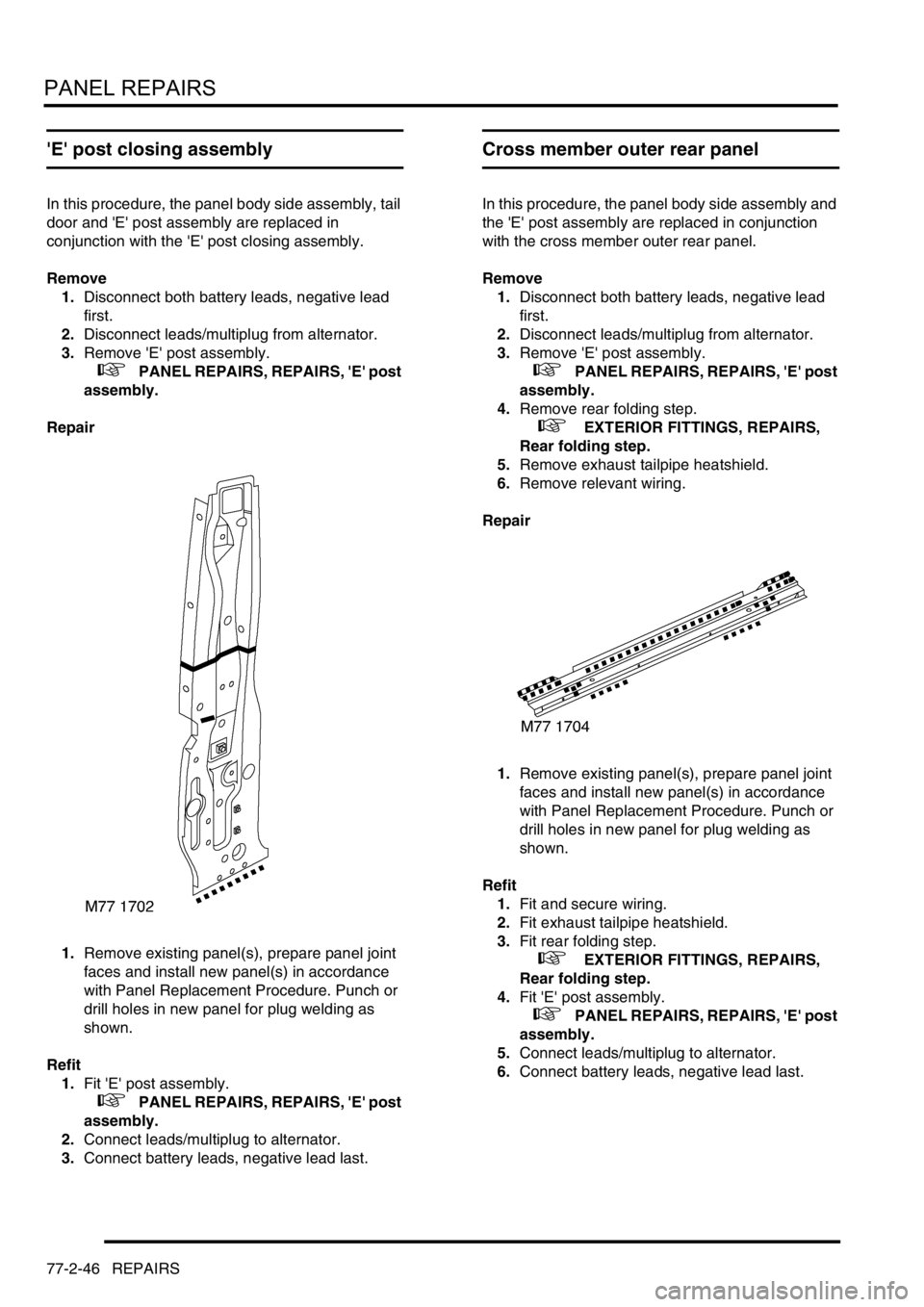
1.Remove existing panel(s), prepare panel joint
faces and install new panel(s) in accordance
with Panel Replacement Procedure. Punch or
drill holes in new panel for plug welding as
shown.
Refit
1.Fit 'E' post assembly.
+ PANEL REPAIRS, REPAIRS, 'E' post
assembly.
2.Connect leads/multiplug to alternator.
3.Connect battery leads, negative lead last.
Cross member outer rear panel
In this procedure, the panel body side assembly and
the 'E' post assembly are replaced in conjunction
with the cross member outer rear panel.
Remove
1.Disconnect both battery leads, negative lead
first.
2.Disconnect leads/multiplug from alternator.
3.Remove 'E' post assembly.
+ PANEL REPAIRS, REPAIRS, 'E' post
assembly.
4.Remove rear folding step.
+ EXTERIOR FITTINGS, REPAIRS,
Rear folding step.
5.Remove exhaust tailpipe heatshield.
6.Remove relevant wiring.
Repair
1.Remove existing panel(s), prepare panel joint
faces and install new panel(s) in accordance
with Panel Replacement Procedure. Punch or
drill holes in new panel for plug welding as
shown.
Refit
1.Fit and secure wiring.
2.Fit exhaust tailpipe heatshield.
3.Fit rear folding step.
+ EXTERIOR FITTINGS, REPAIRS,
Rear folding step.
4.Fit 'E' post assembly.
+ PANEL REPAIRS, REPAIRS, 'E' post
assembly.
5.Connect leads/multiplug to alternator.
6.Connect battery leads, negative lead last.
Page 1296 of 1672
PANEL REPAIRS
REPAIRS 77-2-47
Cross member outer rear panel (centre
section)
Remove
1.Disconnect both battery leads, negative lead
first.
2.Disconnect leads/multiplug from alternator.
3.Remove loadspace carpet.
+ INTERIOR TRIM COMPONENTS,
REPAIRS, Carpet - loadspace.
4.Remove rear bumper assembly.
+ EXTERIOR FITTINGS, REPAIRS,
Bumper assembly - rear - up to 03MY.
5.Remove rear folding step.
+ EXTERIOR FITTINGS, REPAIRS,
Rear folding step.
6.Remove exhaust tailpipe heatshield.
7.Remove tail door tread plate.
8.Remove head lining rear trim finisher.
9.Remove tail door aperture seal.
10.Remove relevant wiring.
Repair
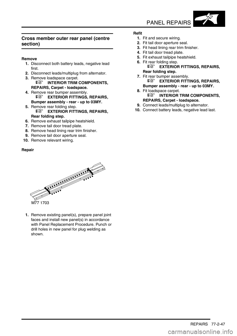
1.Remove existing panel(s), prepare panel joint
faces and install new panel(s) in accordance
with Panel Replacement Procedure. Punch or
drill holes in new panel for plug welding as
shown.Refit
1.Fit and secure wiring.
2.Fit tail door aperture seal.
3.Fit head lining rear trim finisher.
4.Fit tail door tread plate.
5.Fit exhaust tailpipe heatshield.
6.Fit rear folding step.
+ EXTERIOR FITTINGS, REPAIRS,
Rear folding step.
7.Fit rear bumper assembly.
+ EXTERIOR FITTINGS, REPAIRS,
Bumper assembly - rear - up to 03MY.
8.Fit loadspace carpet.
+ INTERIOR TRIM COMPONENTS,
REPAIRS, Carpet - loadspace.
9.Connect leads/multiplug to alternator.
10.Connect battery leads, negative lead last.
Page 1297 of 1672
PANEL REPAIRS
77-2-48 REPAIRS
Cross member outer rear panel (RH/LH
section)
In this procedure, the panel body side assembly and
the 'E' post assembly are replaced in conjunction
with either the RH or LH section of the cross member
outer rear panel.
Remove
1.Disconnect both battery leads, negative lead
first.
2.Disconnect leads/multiplug from alternator.
3.Remove 'E' post assembly.
+ PANEL REPAIRS, REPAIRS, 'E' post
assembly.
4.Remove rear folding step.
+ EXTERIOR FITTINGS, REPAIRS,
Rear folding step.
5. LH side: Remove exhaust tailpipe heatshield.
6.Remove relevant wiring.
Repair
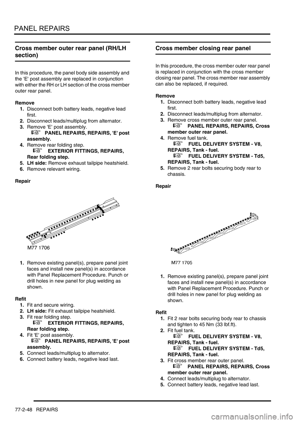
1.Remove existing panel(s), prepare panel joint
faces and install new panel(s) in accordance
with Panel Replacement Procedure. Punch or
drill holes in new panel for plug welding as
shown.
Refit
1.Fit and secure wiring.
2. LH side: Fit exhaust tailpipe heatshield.
3.Fit rear folding step.
+ EXTERIOR FITTINGS, REPAIRS,
Rear folding step.
4.Fit 'E' post assembly.
+ PANEL REPAIRS, REPAIRS, 'E' post
assembly.
5.Connect leads/multiplug to alternator.
6.Connect battery leads, negative lead last.
Cross member closing rear panel
In this procedure, the cross member outer rear panel
is replaced in conjunction with the cross member
closing rear panel. The cross member rear assembly
can also be replaced, if required.
Remove
1.Disconnect both battery leads, negative lead
first.
2.Disconnect leads/multiplug from alternator.
3.Remove cross member outer rear panel.
+ PANEL REPAIRS, REPAIRS, Cross
member outer rear panel.
4.Remove fuel tank.
+ FUEL DELIVERY SYSTEM - V8,
REPAIRS, Tank - fuel.
+ FUEL DELIVERY SYSTEM - Td5,
REPAIRS, Tank - fuel.
5.Remove 2 rear bolts securing body rear to
chassis.
Repair
1.Remove existing panel(s), prepare panel joint
faces and install new panel(s) in accordance
with Panel Replacement Procedure. Punch or
drill holes in new panel for plug welding as
shown.
Refit
1.Fit 2 rear bolts securing body rear to chassis
and tighten to 45 Nm (33 lbf.ft).
2.Fit fuel tank.
+ FUEL DELIVERY SYSTEM - V8,
REPAIRS, Tank - fuel.
+ FUEL DELIVERY SYSTEM - Td5,
REPAIRS, Tank - fuel.
3.Fit cross member rear outer panel.
+ PANEL REPAIRS, REPAIRS, Cross
member outer rear panel.
4.Connect leads/multiplug to alternator.
5.Connect battery leads, negative lead last.
Page 1298 of 1672
PANEL REPAIRS
REPAIRS 77-2-49
Cross member rear assembly
In this procedure, the cross member outer rear panel,
cross member closing rear panel, 'E' post assembly
and the panel body side assembly are replaced in
conjunction with the cross member rear assembly.
Remove
1.Disconnect both battery leads, negative lead
first.
2.Disconnect leads/multiplug from alternator.
3.Remove cross member closing rear panel.
+ PANEL REPAIRS, REPAIRS, Cross
member closing rear panel.
Repair
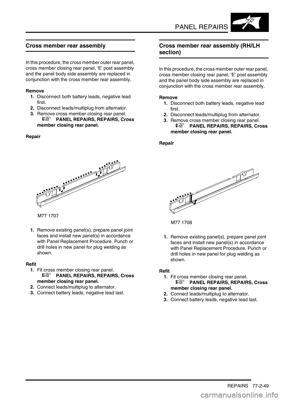
1.Remove existing panel(s), prepare panel joint
faces and install new panel(s) in accordance
with Panel Replacement Procedure. Punch or
drill holes in new panel for plug welding as
shown.
Refit
1.Fit cross member closing rear panel.
+ PANEL REPAIRS, REPAIRS, Cross
member closing rear panel.
2.Connect leads/multiplug to alternator.
3.Connect battery leads, negative lead last.
Cross member rear assembly (RH/LH
section)
In this procedure, the cross member outer rear panel,
cross member closing rear panel, 'E' post assembly
and the panel body side assembly are replaced in
conjunction with the cross member rear assembly.
Remove
1.Disconnect both battery leads, negative lead
first.
2.Disconnect leads/multiplug from alternator.
3.Remove cross member closing rear panel.
+ PANEL REPAIRS, REPAIRS, Cross
member closing rear panel.
Repair
1.Remove existing panel(s), prepare panel joint
faces and install new panel(s) in accordance
with Panel Replacement Procedure. Punch or
drill holes in new panel for plug welding as
shown.
Refit
1.Fit cross member closing rear panel.
+ PANEL REPAIRS, REPAIRS, Cross
member closing rear panel.
2.Connect leads/multiplug to alternator.
3.Connect battery leads, negative lead last.
Page 1300 of 1672
PANEL REPAIRS
REPAIRS 77-2-51
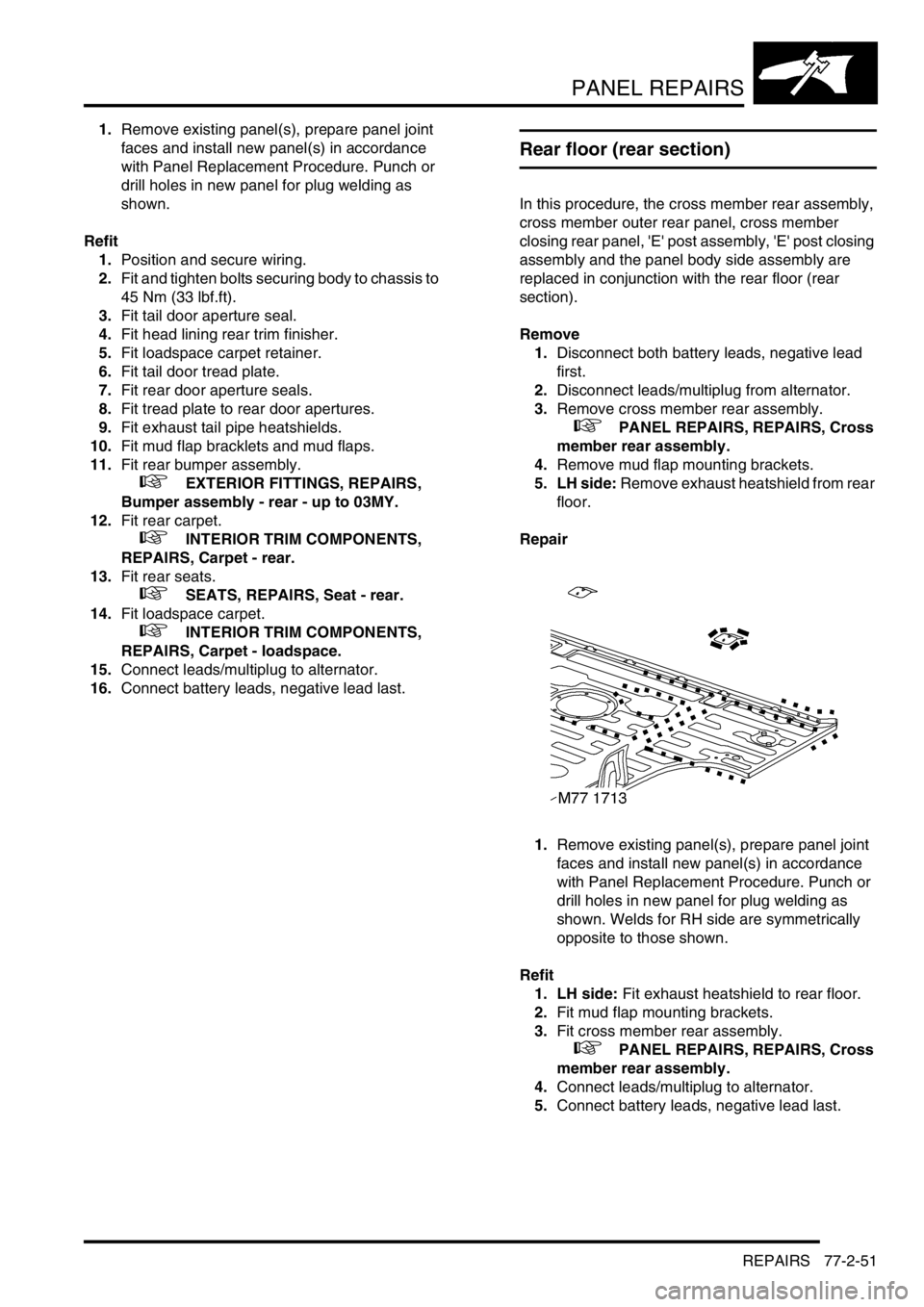
1.Remove existing panel(s), prepare panel joint
faces and install new panel(s) in accordance
with Panel Replacement Procedure. Punch or
drill holes in new panel for plug welding as
shown.
Refit
1.Position and secure wiring.
2.Fit and tighten bolts securing body to chassis to
45 Nm (33 lbf.ft).
3.Fit tail door aperture seal.
4.Fit head lining rear trim finisher.
5.Fit loadspace carpet retainer.
6.Fit tail door tread plate.
7.Fit rear door aperture seals.
8.Fit tread plate to rear door apertures.
9.Fit exhaust tail pipe heatshields.
10.Fit mud flap bracklets and mud flaps.
11.Fit rear bumper assembly.
+ EXTERIOR FITTINGS, REPAIRS,
Bumper assembly - rear - up to 03MY.
12.Fit rear carpet.
+ INTERIOR TRIM COMPONENTS,
REPAIRS, Carpet - rear.
13.Fit rear seats.
+ SEATS, REPAIRS, Seat - rear.
14.Fit loadspace carpet.
+ INTERIOR TRIM COMPONENTS,
REPAIRS, Carpet - loadspace.
15.Connect leads/multiplug to alternator.
16.Connect battery leads, negative lead last.
Rear floor (rear section)
In this procedure, the cross member rear assembly,
cross member outer rear panel, cross member
closing rear panel, 'E' post assembly, 'E' post closing
assembly and the panel body side assembly are
replaced in conjunction with the rear floor (rear
section).
Remove
1.Disconnect both battery leads, negative lead
first.
2.Disconnect leads/multiplug from alternator.
3.Remove cross member rear assembly.
+ PANEL REPAIRS, REPAIRS, Cross
member rear assembly.
4.Remove mud flap mounting brackets.
5. LH side: Remove exhaust heatshield from rear
floor.
Repair
1.Remove existing panel(s), prepare panel joint
faces and install new panel(s) in accordance
with Panel Replacement Procedure. Punch or
drill holes in new panel for plug welding as
shown. Welds for RH side are symmetrically
opposite to those shown.
Refit
1. LH side: Fit exhaust heatshield to rear floor.
2.Fit mud flap mounting brackets.
3.Fit cross member rear assembly.
+ PANEL REPAIRS, REPAIRS, Cross
member rear assembly.
4.Connect leads/multiplug to alternator.
5.Connect battery leads, negative lead last.
Page 1301 of 1672
PANEL REPAIRS
77-2-52 REPAIRS
Rear floor (RH/LH section)
In this procedure, the cross member rear assembly,
cross member outer rear panel (RH/LH section),
cross member closing rear panel, 'E' post assembly,
'E' post closing assembly and the panel body side
assembly are replaced in conjunction with the rear
floor (RH/LH section).
Remove
1.Disconnect both battery leads, negative lead
first.
2.Disconnect leads/multiplug from alternator.
3.Remove cross member rear assembly.
+ PANEL REPAIRS, REPAIRS, Cross
member rear assembly.
4.Remove mud flap mounting brackets.
5. LH side: Remove exhaust heatshield from rear
floor.
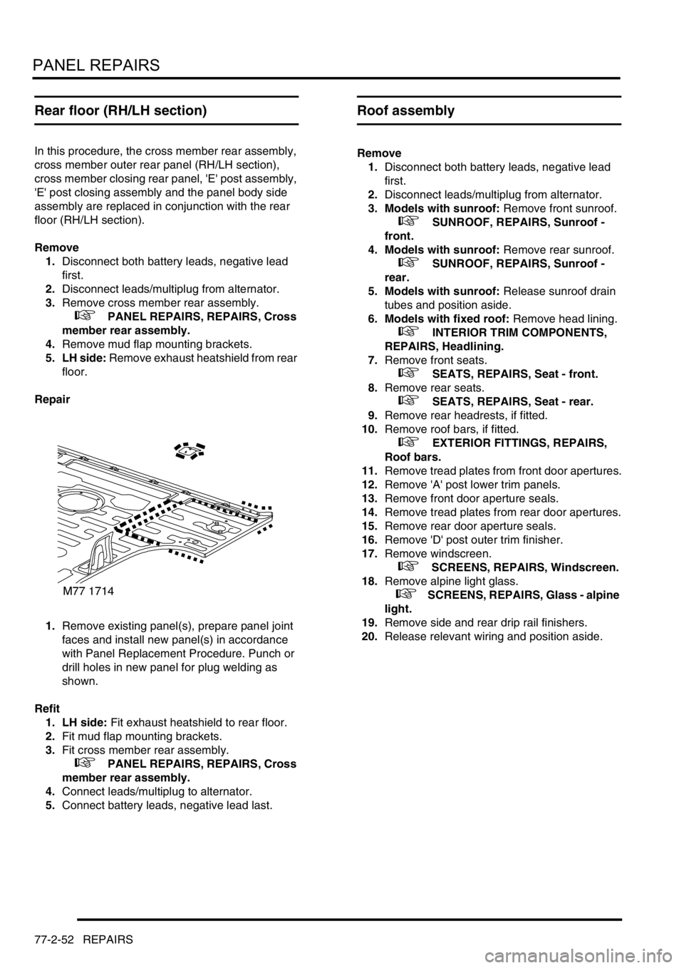
Repair
1.Remove existing panel(s), prepare panel joint
faces and install new panel(s) in accordance
with Panel Replacement Procedure. Punch or
drill holes in new panel for plug welding as
shown.
Refit
1. LH side: Fit exhaust heatshield to rear floor.
2.Fit mud flap mounting brackets.
3.Fit cross member rear assembly.
+ PANEL REPAIRS, REPAIRS, Cross
member rear assembly.
4.Connect leads/multiplug to alternator.
5.Connect battery leads, negative lead last.
Roof assembly
Remove
1.Disconnect both battery leads, negative lead
first.
2.Disconnect leads/multiplug from alternator.
3. Models with sunroof: Remove front sunroof.
+ SUNROOF, REPAIRS, Sunroof -
front.
4. Models with sunroof: Remove rear sunroof.
+ SUNROOF, REPAIRS, Sunroof -
rear.
5. Models with sunroof: Release sunroof drain
tubes and position aside.
6. Models with fixed roof: Remove head lining.
+ INTERIOR TRIM COMPONENTS,
REPAIRS, Headlining.
7.Remove front seats.
+ SEATS, REPAIRS, Seat - front.
8.Remove rear seats.
+ SEATS, REPAIRS, Seat - rear.
9.Remove rear headrests, if fitted.
10.Remove roof bars, if fitted.
+ EXTERIOR FITTINGS, REPAIRS,
Roof bars.
11.Remove tread plates from front door apertures.
12.Remove 'A' post lower trim panels.
13.Remove front door aperture seals.
14.Remove tread plates from rear door apertures.
15.Remove rear door aperture seals.
16.Remove 'D' post outer trim finisher.
17.Remove windscreen.
+ SCREENS, REPAIRS, Windscreen.
18.Remove alpine light glass.
+ SCREENS, REPAIRS, Glass - alpine
light.
19.Remove side and rear drip rail finishers.
20.Release relevant wiring and position aside.
Page 1302 of 1672
PANEL REPAIRS
REPAIRS 77-2-53
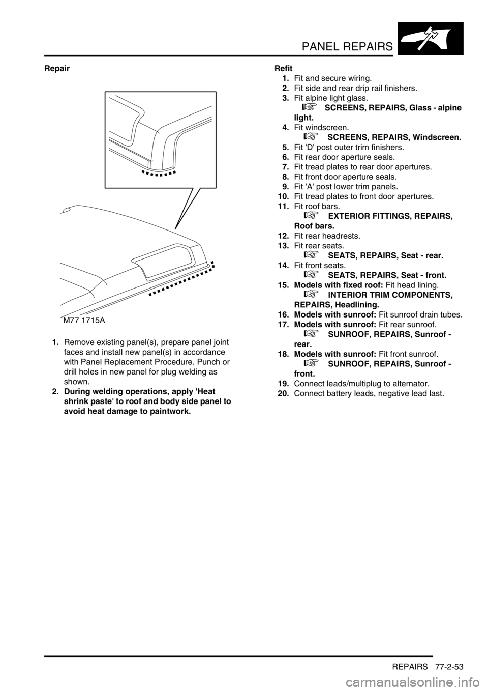
Repair
1.Remove existing panel(s), prepare panel joint
faces and install new panel(s) in accordance
with Panel Replacement Procedure. Punch or
drill holes in new panel for plug welding as
shown.
2. During welding operations, apply 'Heat
shrink paste' to roof and body side panel to
avoid heat damage to paintwork.Refit
1.Fit and secure wiring.
2.Fit side and rear drip rail finishers.
3.Fit alpine light glass.
+ SCREENS, REPAIRS, Glass - alpine
light.
4.Fit windscreen.
+ SCREENS, REPAIRS, Windscreen.
5.Fit 'D' post outer trim finishers.
6.Fit rear door aperture seals.
7.Fit tread plates to rear door apertures.
8.Fit front door aperture seals.
9.Fit 'A' post lower trim panels.
10.Fit tread plates to front door apertures.
11.Fit roof bars.
+ EXTERIOR FITTINGS, REPAIRS,
Roof bars.
12.Fit rear headrests.
13.Fit rear seats.
+ SEATS, REPAIRS, Seat - rear.
14.Fit front seats.
+ SEATS, REPAIRS, Seat - front.
15. Models with fixed roof: Fit head lining.
+ INTERIOR TRIM COMPONENTS,
REPAIRS, Headlining.
16. Models with sunroof: Fit sunroof drain tubes.
17. Models with sunroof: Fit rear sunroof.
+ SUNROOF, REPAIRS, Sunroof -
rear.
18. Models with sunroof: Fit front sunroof.
+ SUNROOF, REPAIRS, Sunroof -
front.
19.Connect leads/multiplug to alternator.
20.Connect battery leads, negative lead last.
M77 1715A
Page 1634 of 1672
INSTRUMENTS
DESCRIPTION AND OPERATION 88-7
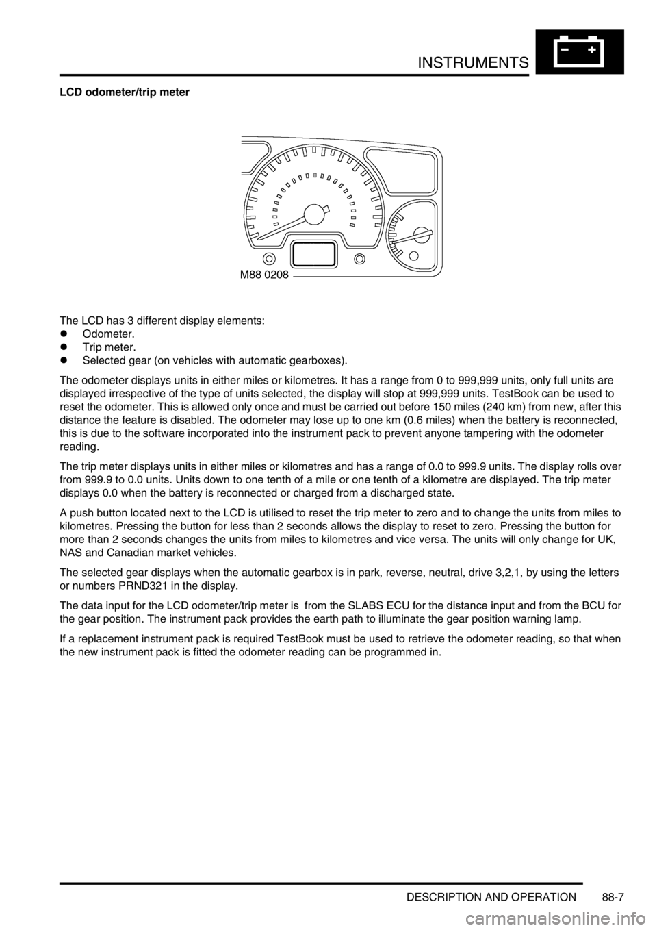
LCD odometer/trip meter
The LCD has 3 different display elements:
lOdometer.
lTrip meter.
lSelected gear (on vehicles with automatic gearboxes).
The odometer displays units in either miles or kilometres. It has a range from 0 to 999,999 units, only full units are
displayed irrespective of the type of units selected, the display will stop at 999,999 units. TestBook can be used to
reset the odometer. This is allowed only once and must be carried out before 150 miles (240 km) from new, after this
distance the feature is disabled. The odometer may lose up to one km (0.6 miles) when the battery is reconnected,
this is due to the software incorporated into the instrument pack to prevent anyone tampering with the odometer
reading.
The trip meter displays units in either miles or kilometres and has a range of 0.0 to 999.9 units. The display rolls over
from 999.9 to 0.0 units. Units down to one tenth of a mile or one tenth of a kilometre are displayed. The trip meter
displays 0.0 when the battery is reconnected or charged from a discharged state.
A push button located next to the LCD is utilised to reset the trip meter to zero and to change the units from miles to
kilometres. Pressing the button for less than 2 seconds allows the display to reset to zero. Pressing the button for
more than 2 seconds changes the units from miles to kilometres and vice versa. The units will only change for UK,
NAS and Canadian market vehicles.
The selected gear displays when the automatic gearbox is in park, reverse, neutral, drive 3,2,1, by using the letters
or numbers PRND321 in the display.
The data input for the LCD odometer/trip meter is from the SLABS ECU for the distance input and from the BCU for
the gear position. The instrument pack provides the earth path to illuminate the gear position warning lamp.
If a replacement instrument pack is required TestBook must be used to retrieve the odometer reading, so that when
the new instrument pack is fitted the odometer reading can be programmed in.