2002 LAND ROVER DISCOVERY engine oil
[x] Cancel search: engine oilPage 908 of 1672

STEERING
ADJUSTMENTS 57-21
13.Remove bolt from steering box pipe retaining
clip. Leaving the PAS reservoir oil pipe in place,
release pipe retaining clip and PAS cooler pipe
from steering box, discard the seal.
14.Fit tool LRT-57-041 to steering box housing.
15.Fit seal to PAS oil cooler pipe.
16.Fit PAS cooler pipe to LRT-57-041 align the
retaining clip to pipes and tighten bolt to 24 Nm
(18 lbf.ft).
17.Connect test hoses LRT-57-002 to LRT-57-
041 and tighten unions. Ensure all pipes and
fittings are clear of engine rotating parts.18.Hang pressure gauge in a safe position under
bonnet.
19. LHD only: Fit turbocharger intercooler feed
pipe and vacuum connection and fit PAS
reservoir to mounting bracket. Fit air intake
hose to turbocharger and air cleaner and
connect multiplug to MAF sensor. The above
parts must be refitted in order to run the
engine.
20.Fill PAS reservoir, connect battery earth lead.
Start engine and allow air to bleed from PAS
system, by turning steering from lock to lock.
Stop engine and check PAS fluid level.
21.Ensure steering system is free from leaks and
maintain maximum fluid level during test.
22.Open the test valve on LRT-57-001 and start
the engine.
23.With the engine at idle and normal running
temperature, slowly turn the steering wheel and
hold on lock.
24.Note reading on pressure gauge.
25.Repeat pressure check on opposite lock, again
noting the reading on the pressure gauge.
26.The test pressure should be between 21 and 62
bar, (300 to 900 lbf/in
2. Pressure will rise to 62
bar (900 lbf/in2) when held on full lock.
27.With the engine at idle, centralise the steering
wheel. Pressure should read 7 bar (100 lbf/in
2)
or below.
28.Pressure outside the above tolerance indicates
a fault.
29.To determine if fault is in steering pump or
steering rack, close the valve on LRT-57-001
for a maximum of five seconds. Pump damage
may occur if test valve is closed for longer
periods.
30.If the gauge does not register between 75 and
103 bar, (1500 lbf/in
2) (maximum pump
pressure), the pump is faulty.
31.If maximum pump pressure is obtained,
suspect the steering box.
32.On completion, stop engine, disconnect battery
earth lead and syphon fluid from PAS reservoir.
33. LHD only: Disconnect multiplug from MAF
sensor, remove air intake hose clips and move
hose aside.
34. LHD only: Release PAS reservoir from
mounting, for access to turbocharger
intercooler pipe.Remove vacuum hose from
turbocharger intercooler pipe.Release clips and
disconnect intercooler pipe from turbocharger.
35.Remove test equipment from tool LRT-57-041.
36.Remove bolt and clip from steering box.
37.Release PAS cooler pipe from tool LRT-57-041
and discard seal. leaving PAS reservoir oil pipe
in place, release tool LRT-57-041 from
steering box and discard seal.
Page 912 of 1672

STEERING
ADJUSTMENTS 57-25
7.Syphon PAS fluid from reservoir.
8.Position container to collect PAS fluid spillage.
9.Clean steering box pipe pipe housing.
10.Remove bolt securing pipe clip to steering box.
Leaving the feed pipe from PAS reservoir in
place, release clip and PAS cooler pipe from
steering box. Discard lower 'O' ring.
11.Fit LRT-57-041 adaptor to steering box.
12.Fit PAS cooler pipe to LRT-57-041, align
retaining clip and tighten Allen bolt to 25 Nm (18
lbf.ft).
13.Hang pressure gauge in a safe position under
bonnet.
14.Remove PAS reservoir filler cap, fill to level
indicator and refit cap.
15.Connect battery earth lead.
16.Start engine and allow air to bleed from PAS
system by turning steering from lock to lock.
Stop engine and check PAS fluid level.
17.Ensure steering system and test equipment are
free from leaks.
18.Open test valve on LRT-57-001 and start
engine.
19.With the engine at idle, slowly turn the steering
wheel and hold on full lock.
20.Note the pressure reading on LRT-57-005.21.Repeat the pressure check for the opposite full
lock.
22.Test pressure should be between 21 and 62
bar, (300 to 900) psi. Dependant on road
surface.
23.With the engine at idle, centralise the steering
wheel. Pressure should read 7 bar (100 psi) or
below.
24.Pressure outside the above tolerance indicates
a fault.
25.To determine if fault is in steering pump or
steering box, close the valve on LRT-57-001 for
a maximum of 5 seconds. Pump damage may
occur if test valve is closed for longer periods.
26.If gauge does not register between 75 and 103
bar, (1500 psi), (maximum pump pressure), the
pump is faulty.
27.If maximum pump pressure is correct suspect
the steering box.
28.On completion stop engine, disconnect battery
earth lead and syphon fluid from PAS reservoir.
29.Remove test equipment from LRT-57-002.
30.Remove bolt and clip from steering box.
31.Release PAS cooler pipe from LRT-57-041 and
discard 'O' ring. Leaving PAS reservoir oil feed
pipe in place, release LRT-57-041 from
steering box and discard 'O' ring.
32.Fit new 'O' rings to PAS cooler pipe.
33.Fit PAS cooler pipe to steering box, align
retaining clip, fit bolt and tighten to 25 Nm (18
lbf.ft).
34.Remove PAS reservoir filler cap, fill to level
indicator and refit cap.
35.Clean chassis member.
36.Fit splash shield and secure with screws.
37.Connect battery earth lead.
38.Start engine.
39.Start engine and allow air to bleed from PAS
system, by turning steering from lock to lock.
40.Visually check PAS system for leaks.
41.Check power steering fluid, if aerated, wait until
fluid is free from bubbles then top-up reservoir
to 'UPPER' level mark.
42.Visually check PAS system for leaks.
43.Dismantle test equipment.
Page 916 of 1672

STEERING
REPAIRS 57-29
12. RH drive models with ACE: Position ACE
control arms to access steering box bolts.
13.With assistance remove 4 securing bolts and
remove steering box.
14.Remove centralising bolt from steering box. Refit
1.Fit centralising bolt to steering box.
2. With assistance, position steering box, fit bolts
and tighten to 90 Nm (66 lbf.ft).
3. RH drive models with ACE: Ensure washer is
in place on lower ball joint of anti-roll bar link,
then connect lower ball joint to axle. Tighten nut
to 100 Nm (74 lbf.ft).
4.Position drag link, fit nut and tighten to 80 Nm
(59 lbf.ft).
5.Position Panhard rod, fit bolt and nut and
tighten to 230 Nm (170 lbf.ft).
6.Clean PAS pipe ends and 'O' ring recess.
7.Lubricate new 'O' rings for PAS pipes with clean
PAS fluid.
8.Fit 'O' rings to PAS pipes and position pipes in
steering box. Fit PAS pipe bracket and tighten
bolt to 22 Nm (16 lbf.ft).
9. RHD models: Fit oil filter and housing:
lClean oil filter housing and engine mating
faces.
lLubricate new 'O' ring with clean engine oil
and fit to housing.
lPosition oil filter housing and tighten bolts to
9 Nm (7 lbf.ft).
10.Ensure steering wheel is centralised. Fit
universal joint between steering box and
intermediate shaft and tighten bolts to 25 Nm
(18 lbf.ft).
11.Remove centralising bolt from steering box.
12.Fit road wheel(s) and tighten nuts to 140 Nm
(103 lbf.ft)..
13.Remove stand(s) and lower vehicle.
14.Check and top up engine oil.
15.Bleed PAS system.
+ STEERING, ADJUSTMENTS,
Hydraulic system - bleed.
16.Centralise steering linkage
+ STEERING, ADJUSTMENTS,
Steering linkage - centralise.
Page 944 of 1672

FRONT SUSPENSION
DESCRIPTION AND OPERATION 60-5
Coil springs
Coil springs are fitted to the front axle of the vehicle. The front springs differ between petrol and Diesel variants. Each
spring is retained at its base by the lower spring seat. The top of each spring is located in the upper spring seat
isolator. The upper spring seat is manufactured from natural rubber , with a bonded metal plate and four bonded studs
which provide for the attachment of the damper turret. The rubber isolator reduces noise transmitted to the chassis
and body from the suspension.
The coil springs must be installed correctly. The bottom coil of the spring locates in a recess in the lower spring seat.
The top coil of the spring is ground flat to locate the upper spring seat isolator.
Coil Spring Specifications – Models up to 03 Model Year
The front springs on petrol variants are manufactured from carbon chrome 13.9 mm (0.55 in) diameter bar. The spring
has 7.6 coils and a free length of 377 mm (14.8 in). The petrol front spring is identified by a pink and orange stripe
painted on a number of coils.
The front springs on Diesel variants are manufactured from carbon chrome 13.9 mm (0.55 in) diameter bar. The spring
has 7.6 coils and a free length of 383 mm (15.0 in). The Diesel front spring is identified by a white and purple stripe
painted on a number of coils.
Coil Spring Specifications – Models from 03 Model Year
The introduction of the 03MY vehicle introduced a range of additional spring fitments. These were introduced to cover
the introduction of the 4.6l V8 engine, the fitment of a front mounted winch and to optimise the vehicle trim heights.
The coil springs are manufactured from silicon manganese 13.8 mm or 13.9 mm (0.54 in or 0.55 in) diameter bar. The
following spring data table shows the colour codes, number of coils and spring free length.
Page 959 of 1672

FRONT SUSPENSION
60-20 DESCRIPTION AND OPERATION
ACE Electronic control unit (ECU)
1Body Control Unit (Ref. only)
2Bracket
3ACE Electronic control unit
4Attachment nuts 3 off
The ACE ECU is mounted on a bracket behind the passenger glove box and is identified from the other ECU's by its
single electrical harness connector. The single 36 pin connector is located on the lower face of the ECU and mates
with a connector from the main harness. The connector supplies power, ground, signal and sensor information to/from
the ECU for control of the ACE system.
The ACE ECU receives a battery power supply from fuse 15 in the engine compartment fusebox via the ACE relay,
also located in the engine compartment fusebox. The ECU provides an earth path for the relay coil, energising the
coil and supplying power to the ECU.
An ignition on signal is supplied from the ignition switch via fuse 29 in the passenger compartment fusebox. The
ignition on signal provides an input to the ECU which tells the ECU that ignition has been selected on and initiates a
250 ms start time. The start time is used to prevent functions operating when software routines are being initialised.
The ignition on signal, when removed, tells the ECU that the ignition is off. The ECU will remain powered for thirty
seconds after the ignition is turned off. The thirty second period allows the ECU to store values and fault flags in the
memory. These values are read by the ECU when the next ignition on signal is received.
An engine speed signal is transmitted to the ECU from the Engine Control Module (ECM) as a pulsed digital signal.
The engine speed signal is used by the ACE ECU to detect that the engine is running and hydraulic pressure for ACE
system operation is available.
Page 1055 of 1672

BRAKES
70-10 DESCRIPTION AND OPERATION
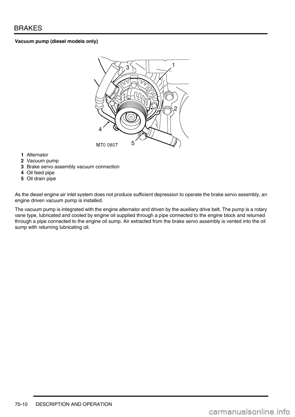
Vacuum pump (diesel models only)
1Alternator
2Vacuum pump
3Brake servo assembly vacuum connection
4Oil feed pipe
5Oil drain pipe
As the diesel engine air inlet system does not produce sufficient depression to operate the brake servo assembly, an
engine driven vacuum pump is installed.
The vacuum pump is integrated with the engine alternator and driven by the auxiliary drive belt. The pump is a rotary
vane type, lubricated and cooled by engine oil supplied through a pipe connected to the engine block and returned
through a pipe connected to the engine oil sump. Air extracted from the brake servo assembly is vented into the oil
sump with returning lubricating oil.
Page 1088 of 1672

BRAKES
REPAIRS 70-43
Refit
1.Clean mating faces of alternator and vacuum
pump.
2.Fit vacuum pump to alternator and tighten
bolts to 8 Nm (6 lbf.ft).
3.Position alternator to engine and connect
multiplug.
4.Connect vacuum hose and oil drain hose to
vacuum pump and secure clips.
5.With assistance align alternator to mounting
bracket and fit but do not tighten bolt.
6.Fit bolt securing support stay to alternator and
tighten to 25 Nm (18 lbf.ft) .
7.Tighten bolt securing alternator to mounting
bracket to 45 Nm (33 lbf.ft).
8.Using new 'O' ring, connect oil supply pipe to
cylinder head and tighten to 10 Nm (7 lbf.ft).
9.Connect lead to alternator and tighten nut to 6
Nm (4.4 lbf.ft).
10.Fit auxiliary drive belt tensioner and tighten bolt
to 50 Nm (37 lbf.ft).
11.Fit auxiliary drive belt.
+ CHARGING AND STARTING,
REPAIRS, Belt - auxiliary drive.
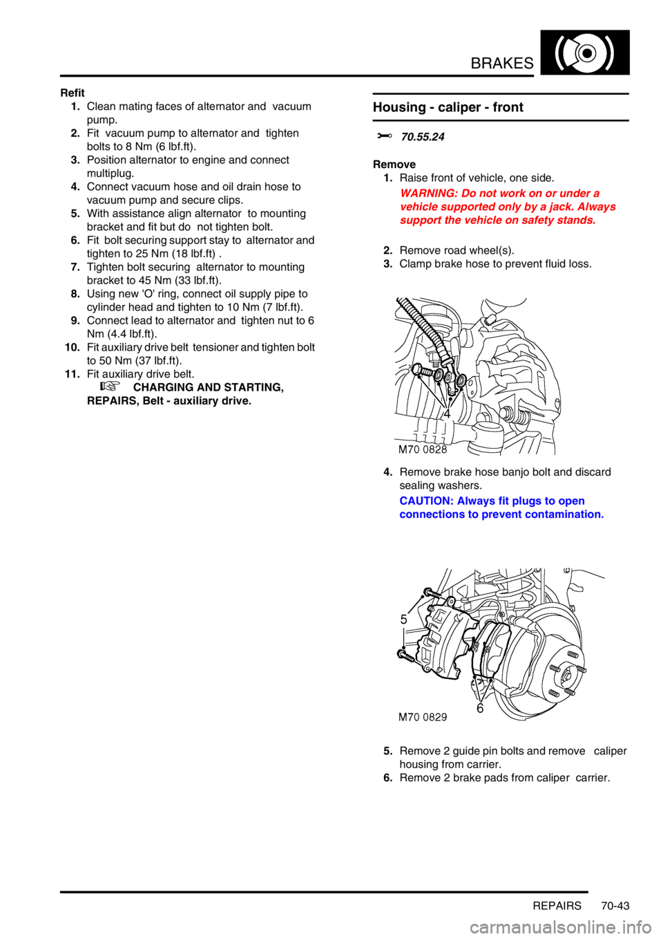
Housing - caliper - front
$% 70.55.24
Remove
1.Raise front of vehicle, one side.
WARNING: Do not work on or under a
vehicle supported only by a jack. Always
support the vehicle on safety stands.
2.Remove road wheel(s).
3.Clamp brake hose to prevent fluid loss.
4.Remove brake hose banjo bolt and discard
sealing washers.
CAUTION: Always fit plugs to open
connections to prevent contamination.
5.Remove 2 guide pin bolts and remove caliper
housing from carrier.
6.Remove 2 brake pads from caliper carrier.
Page 1189 of 1672

SEATS
76-5-4 DESCRIPTION AND OPERATION
Description - electric seats
General
All markets use the same electric seat system. Electically operated lumbar support is optional. The system consists
of an electrical sub-system and a mechanical sub-system.
The electrical sub-system consists of the following components:
lBCU.
lSeat power relays.
lSeat switch packs.
lSeat fore/ aft motors.
lSeat cushion front up/ down motors.
lSeat cushion rear up/ down motors.
lSeat squab motor.
lLumbar pump.
lLumbar deflate solenoid.
The mechanical sub-system consist of the following components:
lGear wheels.
lRack and pinion assemblies.
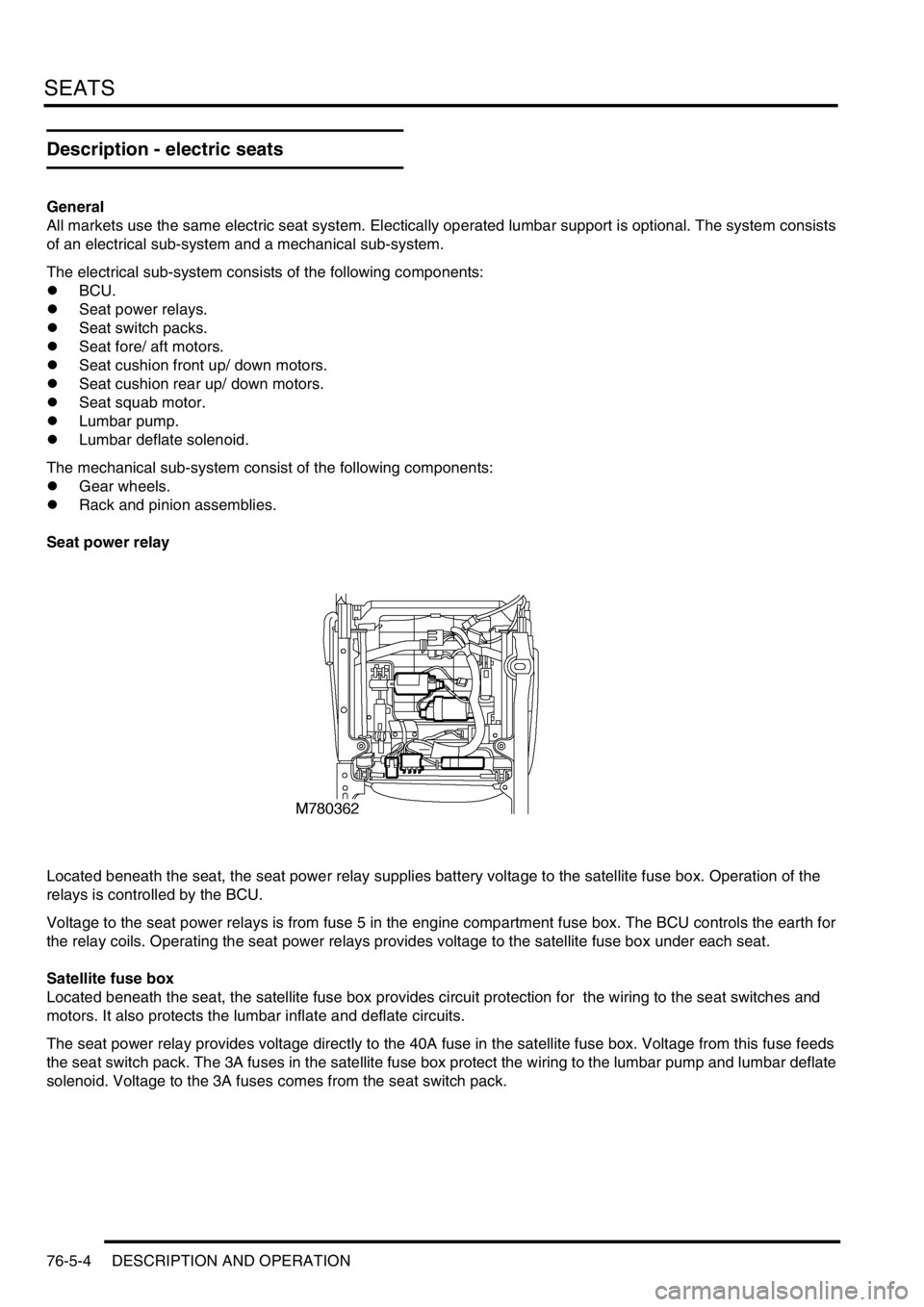
Seat power relay
Located beneath the seat, the seat power relay supplies battery voltage to the satellite fuse box. Operation of the
relays is controlled by the BCU.
Voltage to the seat power relays is from fuse 5 in the engine compartment fuse box. The BCU controls the earth for
the relay coils. Operating the seat power relays provides voltage to the satellite fuse box under each seat.
Satellite fuse box
Located beneath the seat, the satellite fuse box provides circuit protection for the wiring to the seat switches and
motors. It also protects the lumbar inflate and deflate circuits.
The seat power relay provides voltage directly to the 40A fuse in the satellite fuse box. Voltage from this fuse feeds
the seat switch pack. The 3A fuses in the satellite fuse box protect the wiring to the lumbar pump and lumbar deflate
solenoid. Voltage to the 3A fuses comes from the seat switch pack.