2002 LAND ROVER DISCOVERY horn
[x] Cancel search: hornPage 1271 of 1672
PANEL REPAIRS
77-2-22 REPAIRS
18.Fit front wing.
+ EXTERIOR FITTINGS, REPAIRS,
Wing - front - up to 03MY.
19.Connect leads/multiplug to alternator.
20.Connect battery leads, negative lead last.Bonnet locking platform
Remove
1.Disconnect both battery leads, negative lead
first.
2.Disconnect leads/multiplug from alternator.
3.Remove front bumper assembly.
+ EXTERIOR FITTINGS, REPAIRS,
Bumper assembly - front.
4. Models with A/C: Remove condensor.
+ AIR CONDITIONING, REPAIRS,
Condenser.
5. Diesel models: Remove gearbox fluid cooler.
6.Remove RH and LH headlamps.
+ LIGHTING, REPAIRS, Headlamp - up
to 03MY.
7.Remove RH and LH repeater lamps.
+ LIGHTING, REPAIRS, Lamp - front
repeater.
8.Release headlamp wiring and position aside.
9.Remove battery.
+ CHARGING AND STARTING,
REPAIRS, Battery.
10.Remove battery tray.
11.Remove air filter assembly.
+ ENGINE MANAGEMENT SYSTEM -
Td5, REPAIRS, Air filter assembly.
+ ENGINE MANAGEMENT SYSTEM -
V8, REPAIRS, Air cleaner assembly.
12.Remove RH horn.
+ ALARM SYSTEM AND HORN,
REPAIR, Vehicle horn.
13.Remove bonnet release cable.
14.Support bonnet in open position
15.Remove bonnet locking mechanism.
16.Remove VIN plate.
17.Remove centre braces.
Page 1272 of 1672
PANEL REPAIRS
REPAIRS 77-2-23
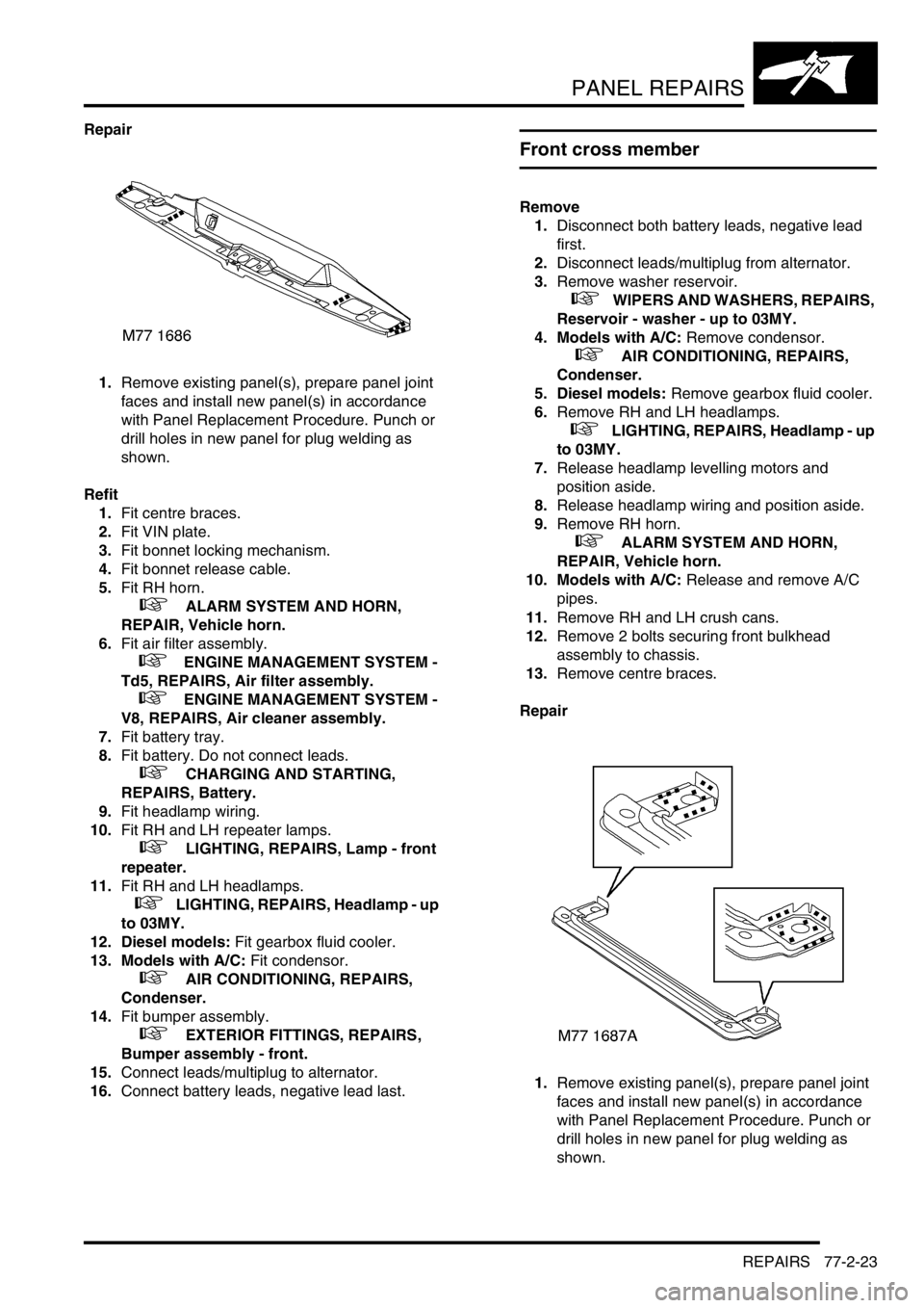
Repair
1.Remove existing panel(s), prepare panel joint
faces and install new panel(s) in accordance
with Panel Replacement Procedure. Punch or
drill holes in new panel for plug welding as
shown.
Refit
1.Fit centre braces.
2.Fit VIN plate.
3.Fit bonnet locking mechanism.
4.Fit bonnet release cable.
5.Fit RH horn.
+ ALARM SYSTEM AND HORN,
REPAIR, Vehicle horn.
6.Fit air filter assembly.
+ ENGINE MANAGEMENT SYSTEM -
Td5, REPAIRS, Air filter assembly.
+ ENGINE MANAGEMENT SYSTEM -
V8, REPAIRS, Air cleaner assembly.
7.Fit battery tray.
8.Fit battery. Do not connect leads.
+ CHARGING AND STARTING,
REPAIRS, Battery.
9.Fit headlamp wiring.
10.Fit RH and LH repeater lamps.
+ LIGHTING, REPAIRS, Lamp - front
repeater.
11.Fit RH and LH headlamps.
+ LIGHTING, REPAIRS, Headlamp - up
to 03MY.
12. Diesel models: Fit gearbox fluid cooler.
13. Models with A/C: Fit condensor.
+ AIR CONDITIONING, REPAIRS,
Condenser.
14.Fit bumper assembly.
+ EXTERIOR FITTINGS, REPAIRS,
Bumper assembly - front.
15.Connect leads/multiplug to alternator.
16.Connect battery leads, negative lead last.
Front cross member
Remove
1.Disconnect both battery leads, negative lead
first.
2.Disconnect leads/multiplug from alternator.
3.Remove washer reservoir.
+ WIPERS AND WASHERS, REPAIRS,
Reservoir - washer - up to 03MY.
4. Models with A/C: Remove condensor.
+ AIR CONDITIONING, REPAIRS,
Condenser.
5. Diesel models: Remove gearbox fluid cooler.
6.Remove RH and LH headlamps.
+ LIGHTING, REPAIRS, Headlamp - up
to 03MY.
7.Release headlamp levelling motors and
position aside.
8.Release headlamp wiring and position aside.
9.Remove RH horn.
+ ALARM SYSTEM AND HORN,
REPAIR, Vehicle horn.
10. Models with A/C: Release and remove A/C
pipes.
11.Remove RH and LH crush cans.
12.Remove 2 bolts securing front bulkhead
assembly to chassis.
13.Remove centre braces.
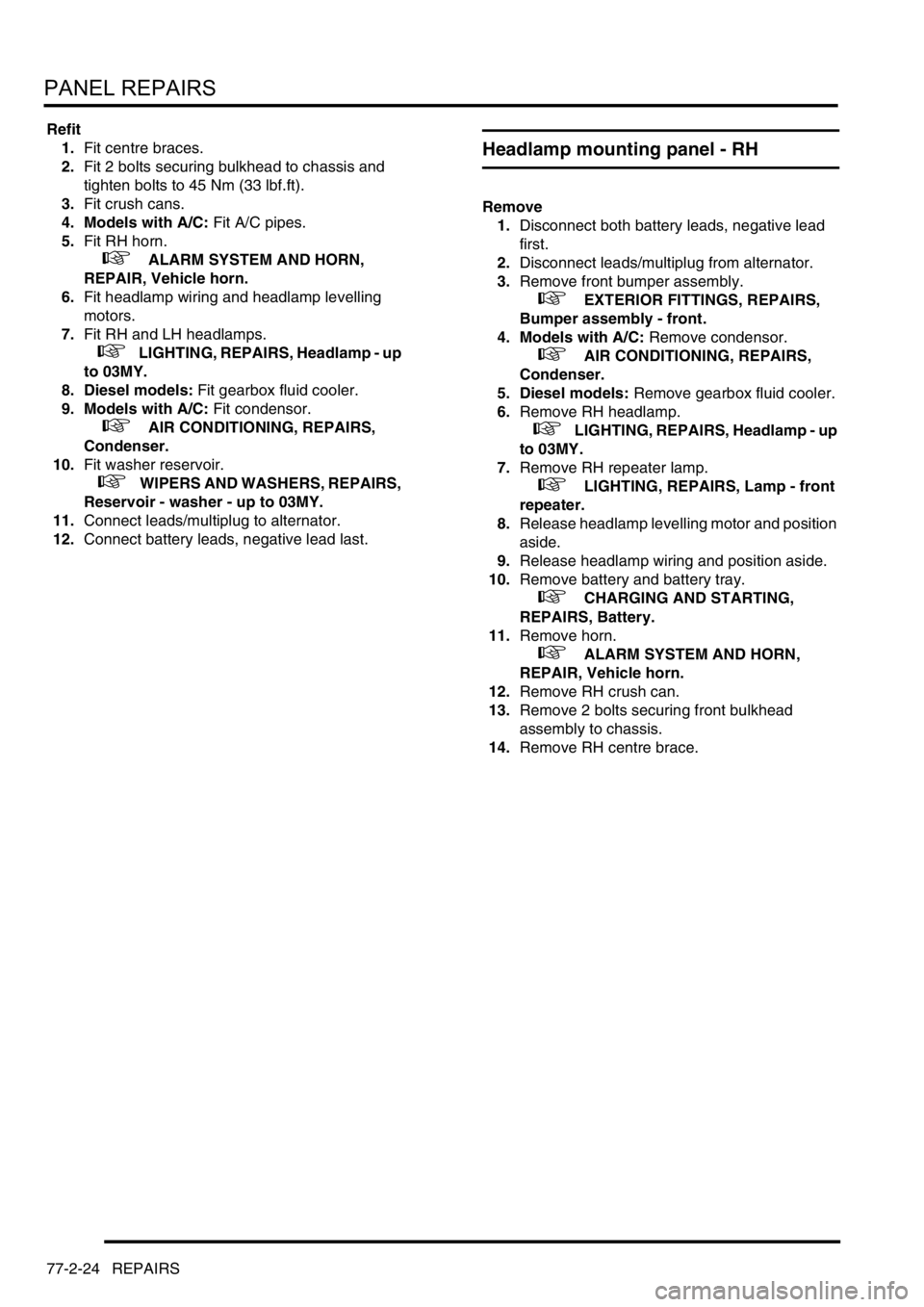
Repair
1.Remove existing panel(s), prepare panel joint
faces and install new panel(s) in accordance
with Panel Replacement Procedure. Punch or
drill holes in new panel for plug welding as
shown.
Page 1273 of 1672
PANEL REPAIRS
77-2-24 REPAIRS
Refit
1.Fit centre braces.
2.Fit 2 bolts securing bulkhead to chassis and
tighten bolts to 45 Nm (33 lbf.ft).
3.Fit crush cans.
4. Models with A/C: Fit A/C pipes.
5.Fit RH horn.
+ ALARM SYSTEM AND HORN,
REPAIR, Vehicle horn.
6.Fit headlamp wiring and headlamp levelling
motors.
7.Fit RH and LH headlamps.
+ LIGHTING, REPAIRS, Headlamp - up
to 03MY.
8. Diesel models: Fit gearbox fluid cooler.
9. Models with A/C: Fit condensor.
+ AIR CONDITIONING, REPAIRS,
Condenser.
10.Fit washer reservoir.
+ WIPERS AND WASHERS, REPAIRS,
Reservoir - washer - up to 03MY.
11.Connect leads/multiplug to alternator.
12.Connect battery leads, negative lead last.
Headlamp mounting panel - RH
Remove
1.Disconnect both battery leads, negative lead
first.
2.Disconnect leads/multiplug from alternator.
3.Remove front bumper assembly.
+ EXTERIOR FITTINGS, REPAIRS,
Bumper assembly - front.
4. Models with A/C: Remove condensor.
+ AIR CONDITIONING, REPAIRS,
Condenser.
5. Diesel models: Remove gearbox fluid cooler.
6.Remove RH headlamp.
+ LIGHTING, REPAIRS, Headlamp - up
to 03MY.
7.Remove RH repeater lamp.
+ LIGHTING, REPAIRS, Lamp - front
repeater.
8.Release headlamp levelling motor and position
aside.
9.Release headlamp wiring and position aside.
10.Remove battery and battery tray.
+ CHARGING AND STARTING,
REPAIRS, Battery.
11.Remove horn.
+ ALARM SYSTEM AND HORN,
REPAIR, Vehicle horn.
12.Remove RH crush can.
13.Remove 2 bolts securing front bulkhead
assembly to chassis.
14.Remove RH centre brace.
Page 1274 of 1672
PANEL REPAIRS
REPAIRS 77-2-25
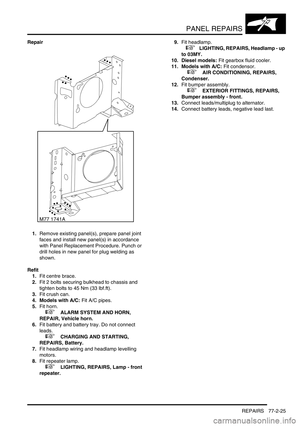
Repair
1.Remove existing panel(s), prepare panel joint
faces and install new panel(s) in accordance
with Panel Replacement Procedure. Punch or
drill holes in new panel for plug welding as
shown.
Refit
1.Fit centre brace.
2.Fit 2 bolts securing bulkhead to chassis and
tighten bolts to 45 Nm (33 lbf.ft).
3.Fit crush can.
4. Models with A/C: Fit A/C pipes.
5.Fit horn.
+ ALARM SYSTEM AND HORN,
REPAIR, Vehicle horn.
6.Fit battery and battery tray. Do not connect
leads.
+ CHARGING AND STARTING,
REPAIRS, Battery.
7.Fit headlamp wiring and headlamp levelling
motors.
8.Fit repeater lamp.
+ LIGHTING, REPAIRS, Lamp - front
repeater.9.Fit headlamp.
+ LIGHTING, REPAIRS, Headlamp - up
to 03MY.
10. Diesel models: Fit gearbox fluid cooler.
11. Models with A/C: Fit condensor.
+ AIR CONDITIONING, REPAIRS,
Condenser.
12.Fit bumper assembly.
+ EXTERIOR FITTINGS, REPAIRS,
Bumper assembly - front.
13.Connect leads/multiplug to alternator.
14.Connect battery leads, negative lead last.
M77 1741A
Page 1472 of 1672
BODY CONTROL UNIT
DESCRIPTION AND OPERATION 86-3-3
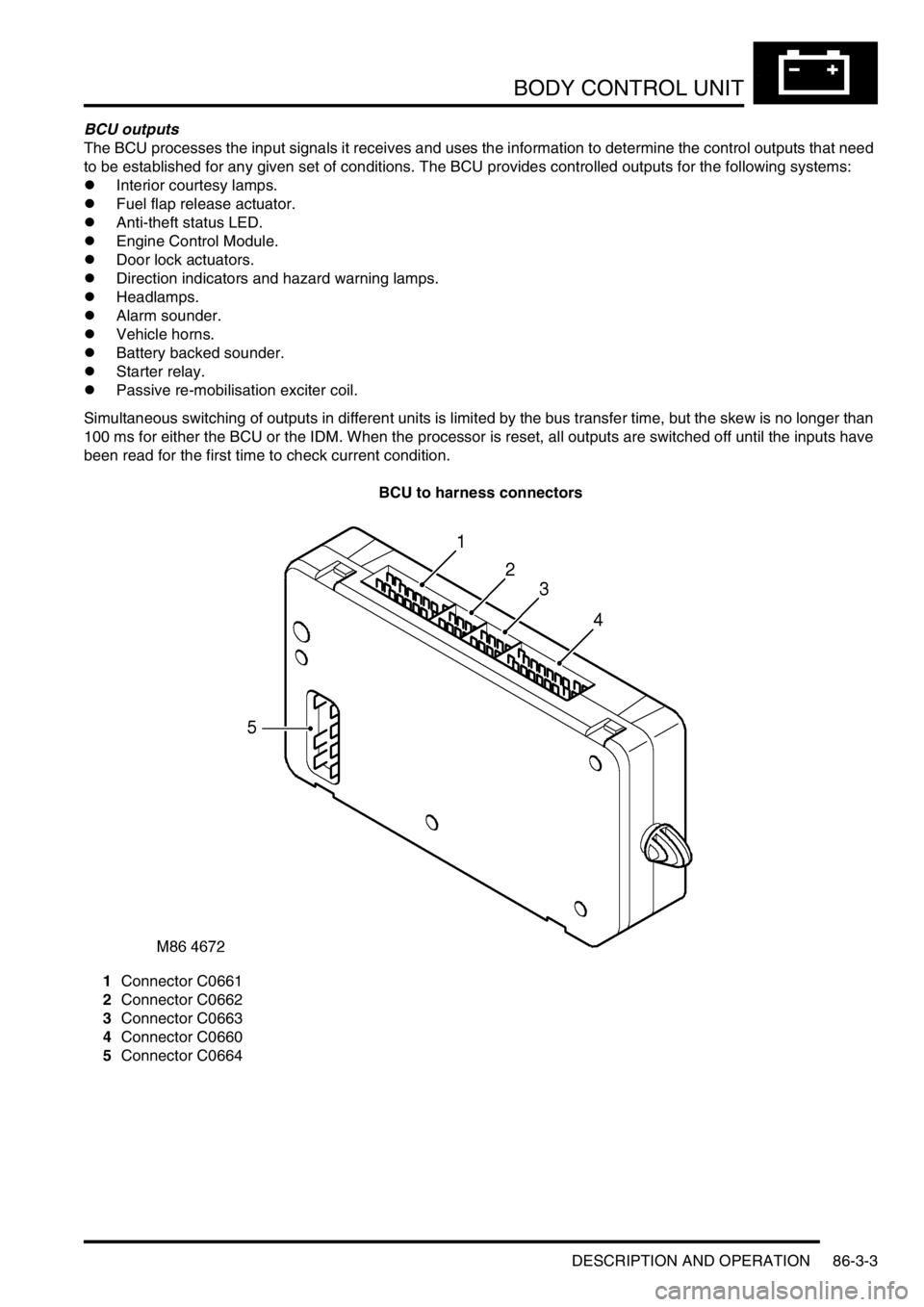
BCU outputs
The BCU processes the input signals it receives and uses the information to determine the control outputs that need
to be established for any given set of conditions. The BCU provides controlled outputs for the following systems:
lInterior courtesy lamps.
lFuel flap release actuator.
lAnti-theft status LED.
lEngine Control Module.
lDoor lock actuators.
lDirection indicators and hazard warning lamps.
lHeadlamps.
lAlarm sounder.
lVehicle horns.
lBattery backed sounder.
lStarter relay.
lPassive re-mobilisation exciter coil.
Simultaneous switching of outputs in different units is limited by the bus transfer time, but the skew is no longer than
100 ms for either the BCU or the IDM. When the processor is reset, all outputs are switched off until the inputs have
been read for the first time to check current condition.
BCU to harness connectors
1Connector C0661
2Connector C0662
3Connector C0663
4Connector C0660
5Connector C0664
Page 1475 of 1672
BODY CONTROL UNIT
86-3-6 DESCRIPTION AND OPERATION
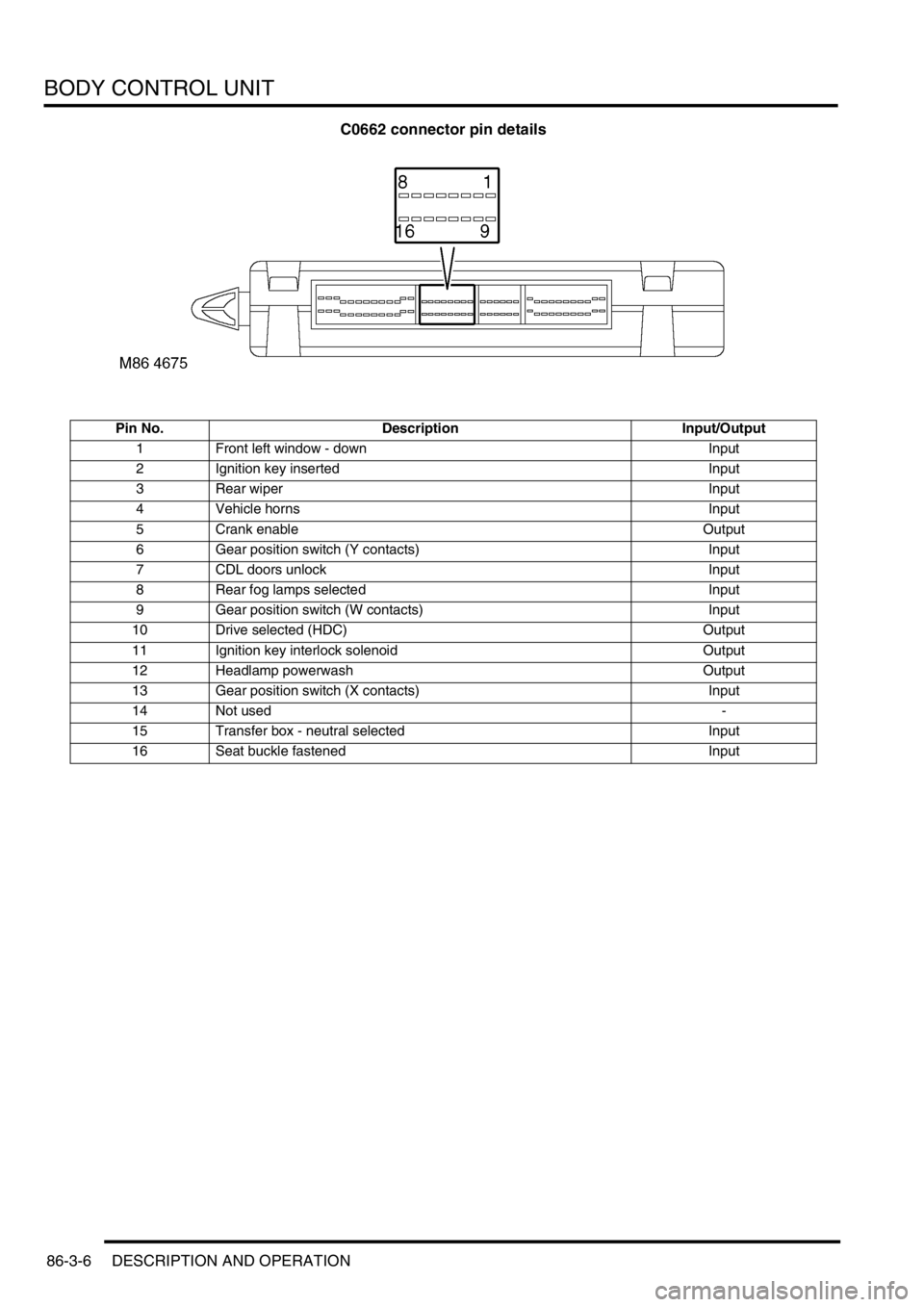
C0662 connector pin details
Pin No. Description Input/Output
1 Front left window - down Input
2 Ignition key inserted Input
3 Rear wiper Input
4 Vehicle horns Input
5 Crank enable Output
6 Gear position switch (Y contacts) Input
7 CDL doors unlock Input
8 Rear fog lamps selected Input
9 Gear position switch (W contacts) Input
10 Drive selected (HDC) Output
11 Ignition key interlock solenoid Output
12 Headlamp powerwash Output
13 Gear position switch (X contacts) Input
14 Not used-
15 Transfer box - neutral selected Input
16 Seat buckle fastened Input
Page 1482 of 1672
BODY CONTROL UNIT
DESCRIPTION AND OPERATION 86-3-13
Anti-theft system
The BCU controls the logical switching operations for enabling and activating the anti-theft system. Features include:
lPerimetric protection – monitors the condition of doors and hinged panels.
lVolumetric protection – monitors the vehicle's interior space.
lRemote locking, superlocking and unlocking functions.
lEngine immobilisation and remobilisation.
lAdvanced mislock detection and automatic compensation.
lEKA code functions.
lCustomer configuration options.
lMarket configuration options.
Immobilisation
The immobilisation system comprises the following components:
lRF receiver.
lRF transmitter/ transponder.
lTransponder coil.
lBCU.
lDoor switches, door lock switches and bonnet switch.
lIDM.
lECM.
lStarter solenoid relay.
lStatus LED.
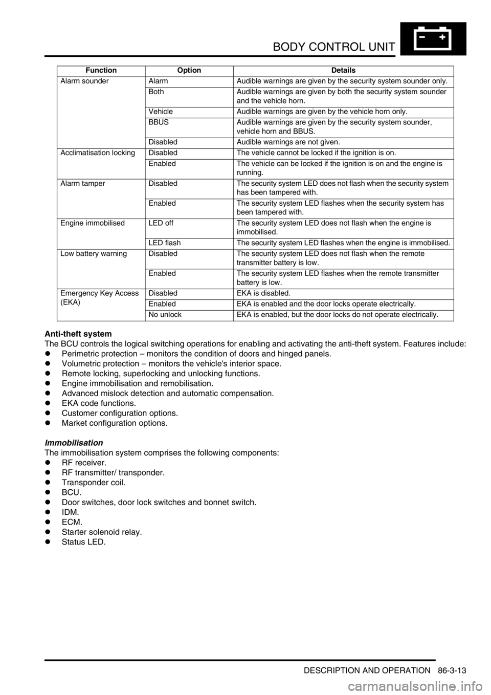
Alarm sounder Alarm Audible warnings are given by the security system sounder only.
Both Audible warnings are given by both the security system sounder
and the vehicle horn.
Vehicle Audible warnings are given by the vehicle horn only.
BBUS Audible warnings are given by the security system sounder,
vehicle horn and BBUS.
Disabled Audible warnings are not given.
Acclimatisation locking Disabled The vehicle cannot be locked if the ignition is on.
Enabled The vehicle can be locked if the ignition is on and the engine is
running.
Alarm tamper Disabled The security system LED does not flash when the security system
has been tampered with.
Enabled The security system LED flashes when the security system has
been tampered with.
Engine immobilised LED off The security system LED does not flash when the engine is
immobilised.
LED flash The security system LED flashes when the engine is immobilised.
Low battery warning Disabled The security system LED does not flash when the remote
transmitter battery is low.
Enabled The security system LED flashes when the remote transmitter
battery is low.
Emergency Key Access
(EKA)Disabled EKA is disabled.
Enabled EKA is enabled and the door locks operate electrically.
No unlock EKA is enabled, but the door locks do not operate electrically. Function Option Details
Page 1483 of 1672

BODY CONTROL UNIT
86-3-14 DESCRIPTION AND OPERATION
Alarm system
The alarm system comprises the following components:
lRF receiver.
lRF transmitter.
lBCU.
lIDM.
lDoor switches, door lock switches and bonnet switch.
lBattery backed-up sounder (BBUS).
lStatus LED.
On non NAS vehicles, power supply for the alarm sounder and the battery BBUS is provided through two relays in the
passenger compartment fuse box. Each of the coils of the alarm relays are directly connected to the IDM which
controls their operation under the direction of BCU signals received via the serial data bus.
On NAS vehicles, an audible warning is provided through operation of the vehicle horns. The BCU provides an earth
path for the coil of the horn relay to initiate vehicle horn operation.
+ ALARM SYSTEM AND HORN, DESCRIPTION AND OPERATION, Description.
Central Door Locking (CDL)
The BCU carries out the logic control operation for CDL. A CDL switch is mounted on the fascia panel and has two
inputs to the BCU, one for lock and one for unlock.
Door locking and unlocking can be performed using the remote transmitter in the keys and the receiver unit located
above the vehicle's headlining, behind the rear sunroof aperture. The receiver detects the signals sent from the
remote transmitter and sends a decoded signal to the BCU for processing.
Four methods of door locking are available:
lRemote handset locking.
lVehicle key locking.
lCDL switch locking.
lSpeed related locking.
Two security levels of door locking are available, CDL and Superlocking. The anti-theft alarm system works in
conjunction with the CDL system.
Electric windows and sunroof
The BCU controls the logical operations and the timing periods for the electric front windows. The rear windows are
hard-wired and the two electric sunroofs are controlled by a dedicated ECU which is enabled by the BCU.
The front windows are electrically operated using two rocker switches located in the centre console. Electric motors
are located in each of the front doors.
The rear windows are enabled by the IDM controlling the operation of the rear window relay located in the passenger
compartment fuse box.
Wipers and washers
The wiper and washer functions are controlled by the BCU and the IDM.
The front wipers and washers are operated from the switch stalk located on the right hand side of the steering column
and only operate when the ignition switch is in position I or II. The front wipers are operated by a motor located below
the windscreen plenum.
+ WIPERS AND WASHERS, DESCRIPTION AND OPERATION, Description.