Page 121 of 1672
MAINTENANCE
10-12 PROCEDURES
Auxiliary drive belt - V8 engine
1.Replace auxiliary drive belt.
+ CHARGING AND STARTING,
REPAIRS, Belt - auxiliary drive.
Auxiliary drive belt - diesel engine
Replace
1.Replace auxiliary drive belt.
+ CHARGING AND STARTING,
REPAIRS, Belt - auxiliary drive.
Fluid reservoirs
Check/top-up — Brake/Clutch reservoir
1.Check fluid level in brake/clutch fluid reservoirs.
2.Clean area around filler cap, remove cap.
3.Top-up if necessary to correct level on reservoir
using recommended fluid.
+ CAPACITIES, FLUIDS AND
LUBRICANTS, Fluids.
4.Fit filler cap.
Check/top-up — PAS/ACE reservoirs
1.Check fluid level in PAS and ACE fluid
reservoirs.
2.Clean area around filler cap, remove cap.
3.Top-up if necessary to correct level on reservoir
using recommended fluid.
+ CAPACITIES, FLUIDS AND
LUBRICANTS, Fluids.
4.Fit filler cap.
Page 124 of 1672

MAINTENANCE
PROCEDURES 10-15
Centrifuge rotor – diesel engine
Replace
1.Replace centrifuge rotor.
+ ENGINE - Td5, REPAIRS, Rotor -
centrifuge.
Engine oil filter - diesel engine
Replace
1.Replace oil filter.
+ ENGINE - Td5, REPAIRS, Filter - oil.
Engine oil filter – V8 engine
WARNING: Avoid excessive skin contact with
used engine oil. Used engine oil contains
potentially harmful contaminants which may
cause skin cancer or other serious skin
disorders.
Replace
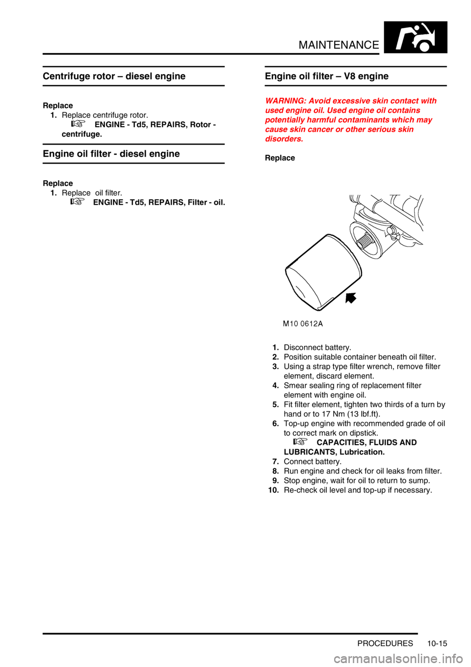
1.Disconnect battery.
2.Position suitable container beneath oil filter.
3.Using a strap type filter wrench, remove filter
element, discard element.
4.Smear sealing ring of replacement filter
element with engine oil.
5.Fit filter element, tighten two thirds of a turn by
hand or to 17 Nm (13 lbf.ft).
6.Top-up engine with recommended grade of oil
to correct mark on dipstick.
+ CAPACITIES, FLUIDS AND
LUBRICANTS, Lubrication.
7.Connect battery.
8.Run engine and check for oil leaks from filter.
9.Stop engine, wait for oil to return to sump.
10.Re-check oil level and top-up if necessary.
Page 131 of 1672
MAINTENANCE
10-22 PROCEDURES
Brake hose, brake, fuel, ACE, clutch
pipes and unions/electrical harnesses
Check – General
1.Check brake servo hose for cracks, leaks and
chafing.
2.Check brake, clutch pipes and unions for
chafing, leaks and corrosion and that all pipes
and hoses are correctly routed and secure.
3.Check electrical harnesses for chafing and
damage.
Check – V8 engine fuel pipes
1.Check fuel pipes and unions for chafing, leaks
and corrosion and that all pipes and hoses are
correctly routed and secure. Check – Diesel engine fuel pipes
1.Check fuel pipes and unions for chafing, leaks
and corrosion and that all pipes and hoses are
correctly routed and secure.
Page 132 of 1672
MAINTENANCE
PROCEDURES 10-23
Power steering, suspension
ACE pipes
1.Check for fluid leaks from power steering and
suspension systems.
2.Check ACE pipes and unions for chafing, leaks
and corrosion and that all pipes and hoses are
correctly routed and secure.
Engine, gearbox, transfer box and axles
Check
1.Check for oil leaks from engine, gearbox
(manual and automatic), transfer box and front
and rear axles; pay particular attention to areas
around oil seals.
Exhaust system
Check
1.Check for signs of exhaust system leaks,
damage and security.
Steering box and front suspension
Check/tighten steering box fixings
1.Check steering box fixings and tighten to 90
Nm (66 lbf.ft).
Check/tighten front axle suspension fixings
Page 136 of 1672
MAINTENANCE
PROCEDURES 10-27
2.Check security of fixings.
+ TORQUE WRENCH SETTINGS,
Front suspension.
+ TORQUE WRENCH SETTINGS, Rear
suspension.
Towing bracket
Check
1.Check security of towing bracket.
Engine mountings - V8 engine
Check for security and condition
1.Check condition of Transfer box - RH mounting
rubber.
2.Check condition of Transfer box - LH mounting
rubber.
3.Check condition of Engine - LH mounting
rubber.
Page 137 of 1672

MAINTENANCE
10-28 PROCEDURES
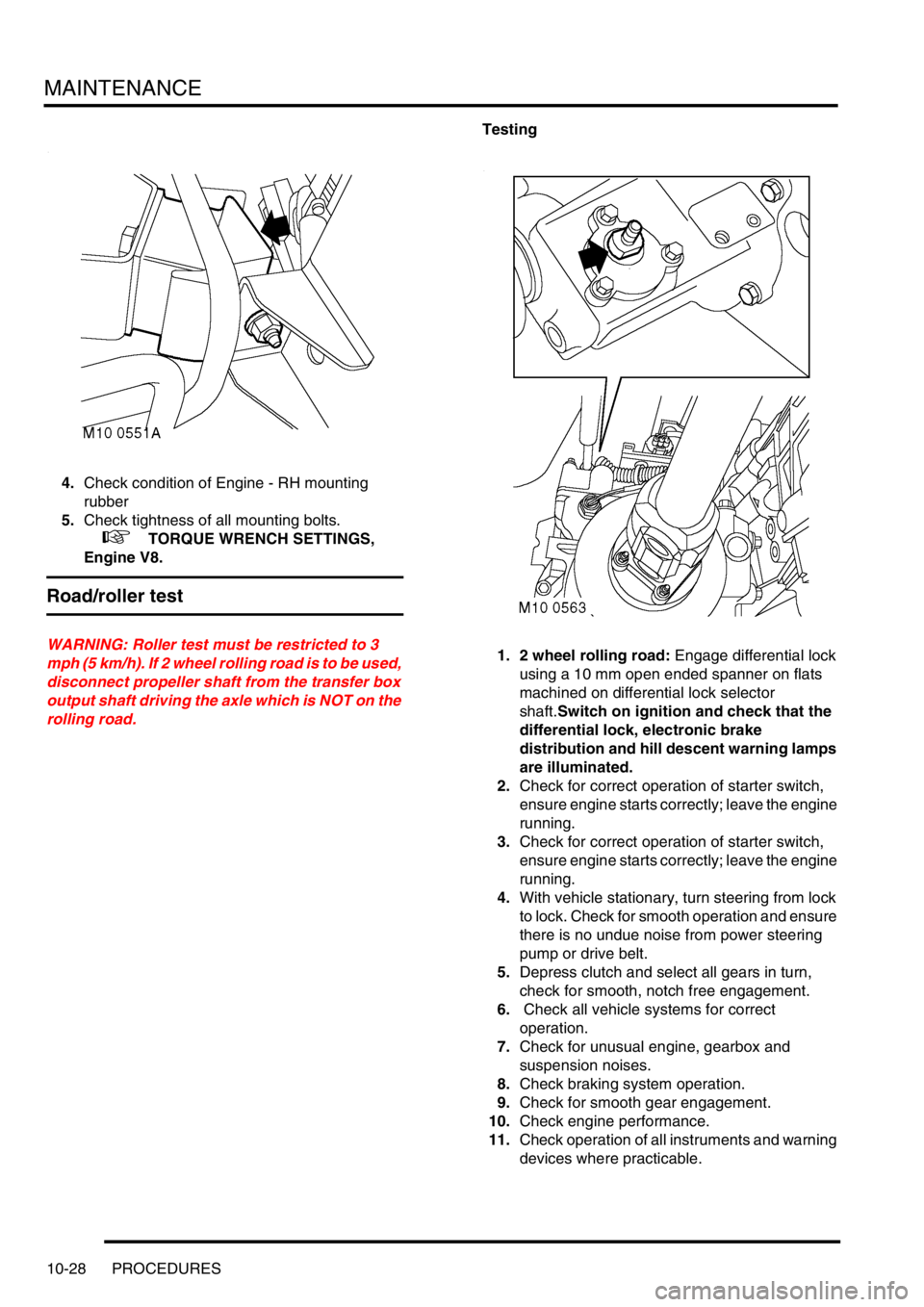
4.Check condition of Engine - RH mounting
rubber
5.Check tightness of all mounting bolts.
+ TORQUE WRENCH SETTINGS,
Engine V8.
Road/roller test
WARNING: Roller test must be restricted to 3
mph (5 km/h). If 2 wheel rolling road is to be used,
disconnect propeller shaft from the transfer box
output shaft driving the axle which is NOT on the
rolling road.Testing
1. 2 wheel rolling road: Engage differential lock
using a 10 mm open ended spanner on flats
machined on differential lock selector
shaft.Switch on ignition and check that the
differential lock, electronic brake
distribution and hill descent warning lamps
are illuminated.
2.Check for correct operation of starter switch,
ensure engine starts correctly; leave the engine
running.
3.Check for correct operation of starter switch,
ensure engine starts correctly; leave the engine
running.
4.With vehicle stationary, turn steering from lock
to lock. Check for smooth operation and ensure
there is no undue noise from power steering
pump or drive belt.
5.Depress clutch and select all gears in turn,
check for smooth, notch free engagement.
6. Check all vehicle systems for correct
operation.
7.Check for unusual engine, gearbox and
suspension noises.
8.Check braking system operation.
9.Check for smooth gear engagement.
10.Check engine performance.
11.Check operation of all instruments and warning
devices where practicable.
Page 174 of 1672
ENGINE - TD5
ADJUSTMENTS 12-1-35
ADJUST ME NTS
Engine oil pressure check
$% 12.90.09.01
Check
1.Remove oil pressure switch.
+ ENGINE - Td5, REPAIRS, Switch -
oil pressure.
2.Connect pressure check kit LRT-12-052C
adaptor and gauge to oil pressure switch
position on oil cooler.
3.Check and if necessary top up engine oil.
4.Run engine at idle speed and check that oil
pressure is within limits given.
+ GENERAL DATA, Engine - Td5.
5.Switch off ignition.
6.Remove pressure check kit LRT-12-052C.
7.Clean oil spillage.
8.Fit oil pressure switch.
+ ENGINE - Td5, REPAIRS, Switch -
oil pressure.
Adjust
1.If engine oil pressure is outside of specified
limits, check condition of oil pump and/or main
and connecting rod bearings.
Page 181 of 1672

ENGINE - TD5
12-1-42 REPAIRS
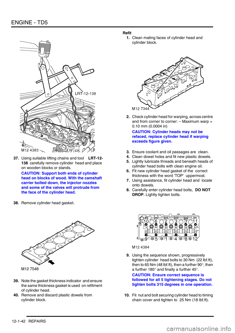
37.Using suitable lifting chains and tool LRT-12-
138 carefully remove cylinder head and place
on wooden blocks or stands.
CAUTION: Support both ends of cylinder
head on blocks of wood. With the camshaft
carrier bolted down, the injector nozzles
and some of the valves will protrude from
the face of the cylinder head.
38.Remove cylinder head gasket.
39.Note the gasket thickness indicator and ensure
the same thickness gasket is used on refitment
of cylinder head.
40.Remove and discard plastic dowels from
cylinder block.Refit
1.Clean mating faces of cylinder head and
cylinder block.
2.Check cylinder head for warping, across centre
and from corner to corner: – Maximum warp =
0.10 mm (0.0004 in)
CAUTION: Cylinder heads may not be
refaced, replace cylinder head if warping
exceeds figure given.
3.Ensure coolant and oil passages are clean.
4.Clean dowel holes and fit new plastic dowels.
5.Lightly lubricate threads and beneath heads of
cylinder head bolts with clean engine oil.
6.Fit new cylinder head gasket of the correct
thickness with the word 'TOP' uppermost.
7.Using assistance, fit cylinder head and locate
onto dowels.
8.Carefully enter cylinder head bolts, DO NOT
DROP. Lightly tighten bolts.
9.Using the sequence shown, progressively
tighten cylinder head bolts to 30 Nm (22 lbf.ft),
then to 65 Nm (48 lbf.ft), then a further 90
°, then
a further 180
° and finally a further 45°.
CAUTION: Ensure correct sequence is
followed for all 5 tightening stages. Do not
tighten bolts 315 degrees in one operation.
10.Fit nut and bolt securing cylinder head to timing
chain cover and tighten to 25 Nm (18 lbf.ft).