2002 LAND ROVER DISCOVERY check engine
[x] Cancel search: check enginePage 241 of 1672

ENGINE - TD5
12-1-102 OVERHAUL
Crankshaft
$% 12.21.33.01
Disassembly
1.Remove timing chain and sprockets.
+ ENGINE - Td5, OVERHAUL, Timing
chain and sprockets.
2.Remove crankshaft rear oil seal.
+ ENGINE - Td5, OVERHAUL, Seal -
crankshaft - rear - manual models.
3.Remove connecting rod bearings.
+ ENGINE - Td5, OVERHAUL,
Bearings - connecting rods.
4.Check that cylinder reference number is on
each main bearing cap and make alignment
marks between each main bearing cap and
cylinder block.
5.Starting at No.3 main bearing cap and working
outwards, progressively loosen, then remove 2
bolts securing each cap. Discard main bearing
cap bolts. 6.Fit 2 slave bolts into main bearing cap in turn
and ease bearing caps from cylinder block.
7.Remove and discard plain bearing shells from
each main bearing cap.
8.Using assistance, remove crankshaft.
9.Remove and discard grooved main bearing
shells and 2 thrust washers from cylinder
block.
10.Remove Torx screw securing each oil squirt jet
to cylinder block, remove squirt jets.
11.Clean main bearing shell and thrust washer
locations in cylinder block, ensure bolt holes
are clean and dry.
12.Clean main bearing caps.
13.Clean crankshaft bearing journals, check
oilways are clear.
14.Ensure drillings in oil squirt jets are clear.
Page 242 of 1672

ENGINE - TD5
OVERHAUL 12-1-103
15.Check core plugs in cylinder block for corrosion
or signs of leakage, seal replacement plugs
with Loctite 243.
Crankshaft - Inspection
1.Check crankshaft main and big-end bearings
for scoring, wear and ovality, make 3 checks at
120
° intervals in centre of journals.
lMain bearings = 62.0 mm
± 0.013 mm
(2.441 in
± 0.001 in).
lBig-end bearings = 54.000 mm
± 0.01 mm
(2.125 in
± 0.0004 in).
2. Crankshafts may not be reground, only one
size of main and big-end bearing shell is
available and if journals are found to be
scored, oval or worn, crankshaft must be
replaced. Main and big-end bearing shells
and thrust washers must be replaced
whenever they are removed.
3.Check crankshaft spigot bush for wear, replace
if necessary using the following procedures:
4.Secure crankshaft in a suitably padded vice.
5.Tap a thread in spigot bush to accommodate a
suitable impulse extractor.
6.Fit impulse extractor to spigot bush.
7.Remove spigot bush.
8.Clean spigot bush recess in crankshaft.
9.Fit new spigot bush to crankshaft using a
suitable mandrel. Reassembly
1.Fit oil squirt jets, fit Torx screws and tighten to
8 Nm (6 lbf.ft).
2.Lubricate new, grooved, main bearing shells
with engine oil and fit to cylinder block.
3.Lubricate new thrust washers with engine oil
and fit, grooved side facing outward, to recess
in each side of No.3 main bearing in cylinder
block.
4.Lubricate crankshaft journals with engine oil
and using assistance, position crankshaft in
cylinder block.
5.Lubricate new, plain, main bearing shells with
engine oil and fit to main bearing caps.
6.Fit main bearing caps in their original fitted
positions ensuring reference marks are
aligned.
7.Fit and lightly tighten new main bearing cap
bolts. Do not lubricate bolt threads.
8.Starting with No.3 main bearing cap and
working outwards, tighten main bearing cap
bolts to:
lStage 1 - 33 Nm (24 lbf.ft)
lStage 2 - Further 90
°
CAUTION: Do not carry out stages 1 and
2 in one operation.
9.Check that crankshaft rotates smoothly.
10. Attach a magnetic base DTI to front of cylinder
block with stylus of gauge on end of crankshaft.
Page 254 of 1672

ENGINE - V8
ADJUSTMENTS 12-2-11
ADJUST ME NTS
Engine oil pressure check
$% 12.90.09.01
Check
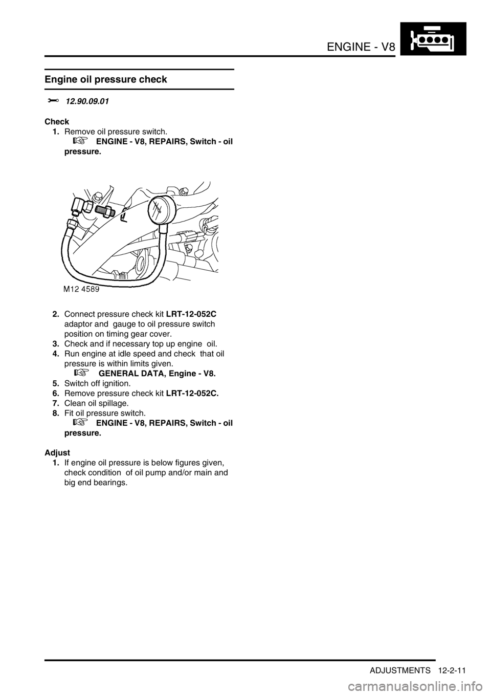
1.Remove oil pressure switch.
+ ENGINE - V8, REPAIRS, Switch - oil
pressure.
2.Connect pressure check kit LRT-12-052C
adaptor and gauge to oil pressure switch
position on timing gear cover.
3.Check and if necessary top up engine oil.
4.Run engine at idle speed and check that oil
pressure is within limits given.
+ GENERAL DATA, Engine - V8.
5.Switch off ignition.
6.Remove pressure check kit LRT-12-052C.
7.Clean oil spillage.
8.Fit oil pressure switch.
+ ENGINE - V8, REPAIRS, Switch - oil
pressure.
Adjust
1.If engine oil pressure is below figures given,
check condition of oil pump and/or main and
big end bearings.
Page 258 of 1672

ENGINE - V8
REPAIRS 12-2-15
10.Remove cylinder head.
CAUTION: Support both ends of cylinder
head on blocks of wood.
11.Remove cylinder head gasket.
Refit
1.Clean mating faces of cylinder block and head
using suitable gasket removal spray and a
plastic scraper, ensure that bolt holes in block
are clean and dry. Clean mating faces of
cylinder head and exhaust manifold.
CAUTION: Do not use a metal scraper or
machined surfaces may be damaged.
2.Check head and block faces for warping and
pitting. If out of specification, renew head.
3.Fit cylinder head gasket with the word 'TOP'
uppermost.
CAUTION: Gaskets must be fitted dry.
4.Carefully fit cylinder head and locate on
dowels.
5.Lightly lubricate new cylinder head bolt threads
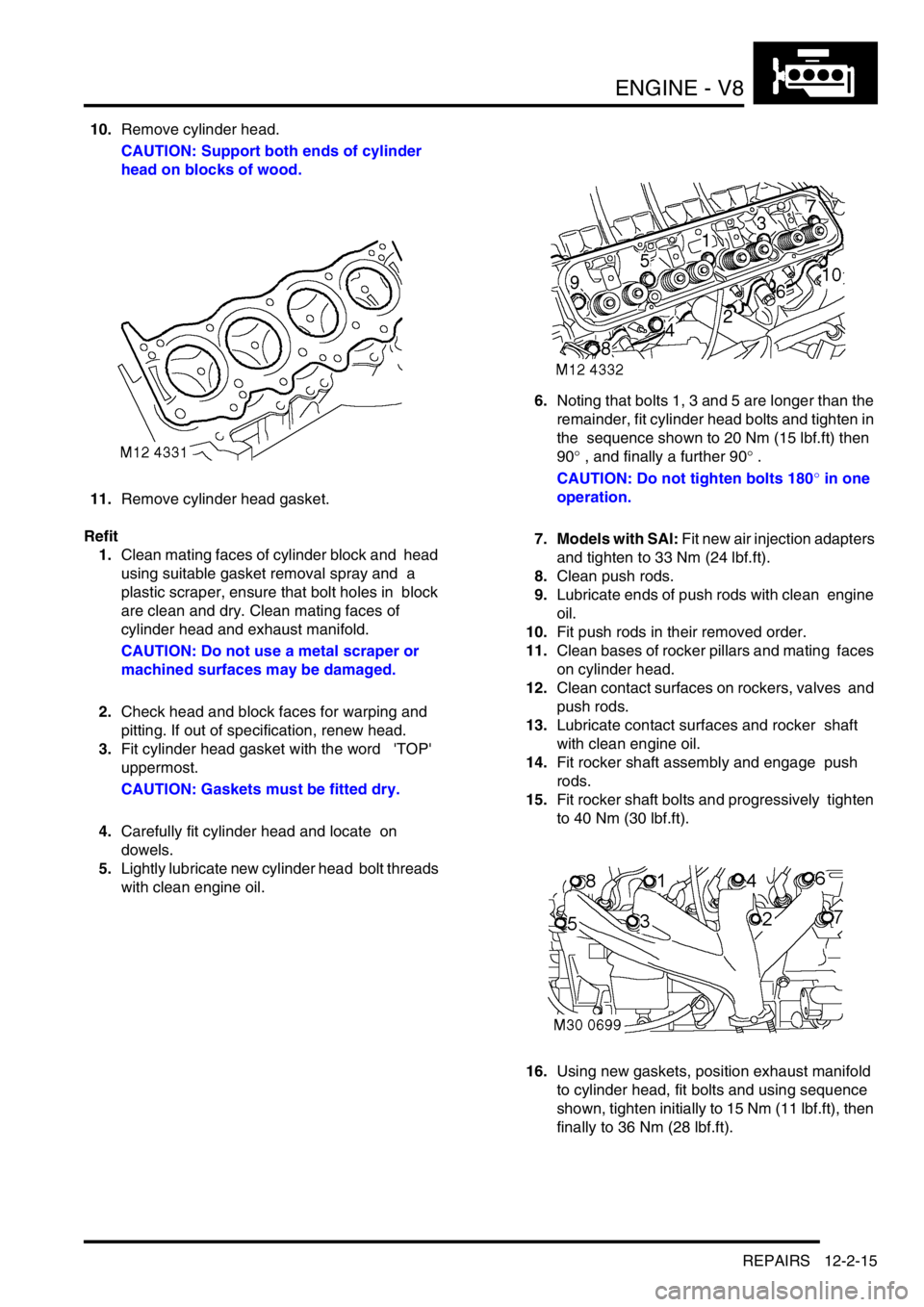
with clean engine oil. 6.Noting that bolts 1, 3 and 5 are longer than the
remainder, fit cylinder head bolts and tighten in
the sequence shown to 20 Nm (15 lbf.ft) then
90
° , and finally a further 90° .
CAUTION: Do not tighten bolts 180
° in one
operation.
7. Models with SAI: Fit new air injection adapters
and tighten to 33 Nm (24 lbf.ft).
8.Clean push rods.
9.Lubricate ends of push rods with clean engine
oil.
10.Fit push rods in their removed order.
11.Clean bases of rocker pillars and mating faces
on cylinder head.
12.Clean contact surfaces on rockers, valves and
push rods.
13.Lubricate contact surfaces and rocker shaft
with clean engine oil.
14.Fit rocker shaft assembly and engage push
rods.
15.Fit rocker shaft bolts and progressively tighten
to 40 Nm (30 lbf.ft).
16.Using new gaskets, position exhaust manifold
to cylinder head, fit bolts and using sequence
shown, tighten initially to 15 Nm (11 lbf.ft), then
finally to 36 Nm (28 lbf.ft).
Page 261 of 1672

ENGINE - V8
12-2-18 REPAIRS
Refit
1.Clean mating faces of cylinder block and head
using suitable gasket removal spray and a
plastic scraper, ensure that bolt holes in block
are clean and dry. Clean mating faces of
cylinder head and exhaust manifold.
CAUTION: Do not use a metal scraper or
machined surfaces may be damaged.
2.Check head and block faces for warping and
pitting. If out of specification, renew head.
3.Fit cylinder head gasket with the word 'TOP'
uppermost.
CAUTION: Gaskets must be fitted dry.
4.Carefully fit cylinder head and locate on
dowels.
5.Lightly lubricate new cylinder head bolt threads
with clean engine oil.
6.Noting that bolts 1, 3 and 5 are longer than the
remainder, fit bolts and tighten in the sequence
shown to 20 Nm (15 lbf.ft) then 90
°, and finally
a further 90
°.
CAUTION: Do not tighten bolts 180
° in one
operation.
7. Models with SAI: Fit new air injection adapters
and tighten to 33 Nm (24 lbf.ft).
8.Clean push rods.
9.Lubricate ends of push rods with clean engine
oil.
10.Fit push rods in their removed order.
11.Clean bases of rocker pillars and mating faces
on cylinder head.
12.Clean contact surfaces on rockers, valves and
push rods.
13.Lubricate contact surfaces and rocker shaft
with clean engine oil.
14.Fit rocker shaft assembly and engage push
rods.
15.Fit rocker shaft bolts and progressively tighten
to 40 Nm (30 lbf.ft). 16.Position alternator mounting bracket, fit bolts
and tighten to 40 Nm (30 lbf.ft).
17.Position auxiliary drive belt tensioner, fit bolt
and tighten to 45 Nm (33 lbf.ft).
18.Connect ht leads to spark plugs in their fitted
order.
19. Using new gaskets, fit exhaust manifold to
cylinder head. Fit bolts and using sequence
shown, tighten initially to 15 Nm (11 lbf.ft), then
finally tighten to 36 Nm (28 lbf.ft).
20. RH drive models: Fit brake servo heat shield.
+ MANIFOLDS AND EXHAUST
SYSTEMS - V8, REPAIRS, Heat shield -
brake servo - Without Secondary Air
Injection.
21.Position engine earth lead, fit bolt and tighten to
22 Nm (16 lbf.ft).
22.Fit inlet manifold gasket.
+ MANIFOLDS AND EXHAUST
SYSTEMS - V8, REPAIRS, Gasket - inlet
manifold - lower.
Page 277 of 1672

ENGINE - V8
12-2-34 REPAIRS
4.Ensure ring gear is correctly seated around the
complete circumference of flywheel and allow
to cool.
5.Fit flywheel.
+ ENGINE - V8, REPAIRS, Flywheel.
Filter - oil
$% 12.60.04
Remove
1.Clean area around filter head and place a
container beneath engine.
2.Using a strap wrench, unscrew and discard
filter.
Refit
1.Clean mating face of filter head.
2.Lubricate sealing ring of new filter with clean
engine oil.
3.Fit filter and tighten by hand until it seats then
tighten a further half turn.
4.Start and run engine to check for leaks.
5.Stop engine, wait a few minutes, then check oil
level.
6.Top up engine oil.
Page 304 of 1672

ENGINE - V8
OVERHAUL 12-2-61
9.Remove cylinder head gasket.
CAUTION: Support both ends of cylinder
head on blocks of wood.
Inspect
1.Clean mating faces of cylinder block and head
using suitable gasket removal spray and a
plastic scraper, ensure that bolt holes in block
are clean and dry.
CAUTION: Do not use a metal scraper or
machined surfaces may be damaged.
2.Check head and block faces for warping and
pitting.
lMaximum cylinder head warp = 0.05 mm
(0.002 in).
Note: Cylinder head can be refaced to 0.50
mm (0.02 in) maximum below head height –
See cylinder head overhaul.Reassembly
1.Fit cylinder head gasket with the word TOP
uppermost.
CAUTION: Gaskets must be fitted dry.
2.Carefully fit cylinder head and locate on
dowels.
3.Lightly lubricate new cylinder head bolt threads
with clean engine oil.
4.Noting that bolts 1, 3 and 5 are longer than the
remainder, fit bolts and tighten in the sequence
shown to 20 Nm (15 lbf.ft) then turn through 90
°, then a further 90 °. CAUTION: Do not
tighten bolts 180
° in one operation.
5.Clean the push rods, Lubricate ends of push
rods with clean engine oil, and fit in their
removed order.
6.Clean bases of rocker pillars and mating faces
on cylinder head.
7.Clean contact surfaces on rockers, valves and
push rods.
8.Lubricate contact surfaces and rocker shaft
with clean engine oil.
9.Fit rocker shaft assembly and engage push
rods.
10.Fit rocker shaft bolts and progressively tighten
to 40 Nm (30 lbf.ft).
11.Connect ht leads to spark plugs in their correct
fitted order.
12. RH cylinder head: Position alternator
mounting bracket, fit bolts and tighten to 40 Nm
(30 lbf.ft).
13. RH cylinder head: Fit auxiliary drive belt
tensioner.
14.Fit inlet manifold gasket.
+ ENGINE - V8, OVERHAUL, Gasket -
inlet manifold.
Page 305 of 1672

ENGINE - V8
12-2-62 OVERHAUL
Cylinder head - overhaul
$% 12.29.19.01
Disassembly
1.Remove cylinder head gasket.
+ ENGINE - V8, OVERHAUL, Gasket -
cylinder head.
2.Loosen screw on tool LRT-12-034.
3.Fit tool LRT-12-034 to valve and tighten screw
to compress valve spring sufficiently to release
collets from valve spring cap.
4.Remove 2 collets and release valve spring
compressor.
5.Remove valve spring cap and valve spring.
6.Remove valve from cylinder head.
7.Remove and discard valve stem oil seal.
8.Repeat above operations for remaining valves.
9.Keep valves, springs, caps and collets in their
fitted order. Inspect
1.Clean mating faces of cylinder block and head
using suitable gasket removal spray and a
plastic scraper, ensure that bolt holes in block
are clean and dry.
CAUTION: Do not use a metal scraper or
machined surfaces may be damaged.
2.Clean cylinder head, valve springs, valves and
inlet valve guide bores. Ensure all loose
particles of carbon are removed on completion.
3.Check head and block faces for warping and
pitting. Maximum warp = 0.05 mm (0.002 in).
4.Check cylinder head height at each end of
head. Renew a head which is outside limits.
a22.94 mm (0.903 in) - New
b62.56 mm (2.463 in) - New
5.Cylinder head can be refaced to 0.50 mm (0.02
in) max. below head height.