Page 1623 of 1672

NAVIGATION SYSTEM
87-8 DESCRIPTION AND OPERATION
17After calibration is achieved, return to the dealership, park the vehicle and stop the engine.
18Turn the ignition switch to position I.
19Use the system settings menu to set the navigation computer to local time and the required units of measure:
aPress the Nav button.
bTurn the RH rotary control to scroll through the displayed menu, highlight TIME and press the RH rotary
control to select. Press the + or – multifunction button to adjust the time in 30 minute steps. Select the 24
hour clock and confirm by pressing the OK multifunction button.
cIf metric units of measure are required, go to step e) (the navigation computer defaults to metric units of
measure).
dIf Imperial units of measure are required, turn the RH rotary control to scroll through the displayed menu,
highlight MEASURING UNIT and press the RH rotary control to select. Turn the RH rotary control to
highlight IMPERIAL and press the RH rotary control to select.
ePress the Nav button to return to the destination menu.
20Calibration is complete. The navigation system is ready for use.
NOTE: The accuracy of the system will automatically be fine tuned when a further journey is made, but this is not
required as part of the calibration procedure.
NOTE: In European countries, the territory will have to be set the first time the navigation system is used, and the
first time a destination in another country is selected. The first time the navigation system is used or a destination
in another country is selected, a map is displayed with the default/current territory highlighted. To change the
territory: Press the RH rotary control to display the territory list; turn the RH rotary control to scroll through the
list and highlight the required territory; press the RH rotary control to confirm the selection.
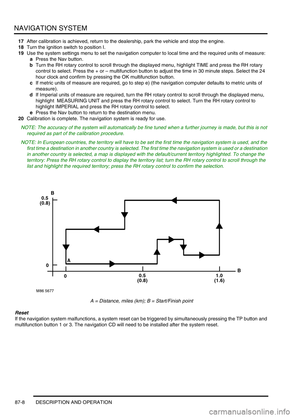
A = Distance, miles (km); B = Start/Finish point
Reset
If the navigation system malfunctions, a system reset can be triggered by simultaneously pressing the TP button and
multifunction button 1 or 3. The navigation CD will need to be installed after the system reset.
Page 1624 of 1672
NAVIGATION SYSTEM
DESCRIPTION AND OPERATION 87-9
Steering Wheel Switches
The steering wheel switches provide remote control operation for some of the navigation computer functions. The
switches can be used to select between the radio/CD/navigation modes, to adjust the volume (in all modes) and to
select search/preset up/down for radio and CD operation.
Remote Control Interface Unit
The remote control interface unit converts the analogue signals from the steering wheel switches into digital signals
for use by the navigation computer. The remote control interface unit is installed in a bracket immediately below the
navigation computer.
The radio remote switches form a resistance ladder between two wires with the resistance across wires dependent
on which switch is pressed. The remote control interface unit monitors the two wires and converts their input into
Instrument (I) bus protocol messages, which it outputs on a dedicated serial link to the navigation computer.
Page 1625 of 1672
NAVIGATION SYSTEM
87-10 DESCRIPTION AND OPERATION
Page 1626 of 1672
NAVIGATION SYSTEM
REPAIRS 87-11
REPAIRS
Interface electronic control unit (ECU) -
remote control
$% 86.53.15
Remove
1.Remove navigation display unit.
+ NAVIGATION SYSTEM, REPAIRS,
Display unit.
2.Remove automatic temperature control unit.
+ AIR CONDITIONING, REPAIRS, ECU
- air temperature control.
3.Remove 2 nuts securing interface carrier
bracket, carefully pull bracket out of fascia.
4.Release interface ECU from bracket,
disconnect multiplug and remove ECU.Refit
1.Secure interface ECU in bracket and connect
multiplug.
2.Carefully position carrier bracket in fascia,
secure with nuts and tighten to 10 Nm (7 lbf.ft).
3.Fit automatic temperature control unit.
+ AIR CONDITIONING, REPAIRS, ECU
- air temperature control.
4.Fit navigation display unit.
+ NAVIGATION SYSTEM, REPAIRS,
Display unit.
M86 5760
M86 5762
Page 1627 of 1672
NAVIGATION SYSTEM
87-12 REPAIRS
Display unit
$% 86.53.20
Remove
1.Fit tool LRT-86-009 into slots ensuring correct
handed key is in correct slot.
The tools are stamped either 'TOP L' or 'TOP
R', ensure the stamping is facing upwards
when removing the unit.
2.Pull display unit from fascia.
3.Disconnect 3 multiplugs and 2 coax cables
from display unit and remove unit.
4.Push display unit retaining clips inwards and
remove keys.Refit
1.Position display unit to fascia, connect
multiplugs and coax cables.
2.Push display unit into fascia until retaining clips
engage.
3.Enter security code and check system is
operational.
M86 5824
M86 5825