2002 LAND ROVER DISCOVERY instrument panel
[x] Cancel search: instrument panelPage 1165 of 1672

INTERIOR TRIM COMPONENTS
76-3-12 REPAIRS
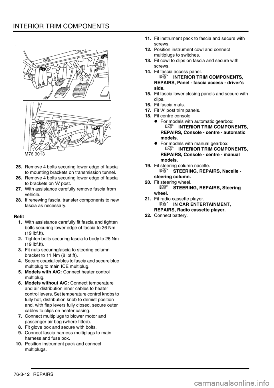
25.Remove 4 bolts securing lower edge of fascia
to mounting brackets on transmission tunnel.
26.Remove 4 bolts securing lower edge of fascia
to brackets on 'A' post.
27.With assistance carefully remove fascia from
vehicle.
28.If renewing fascia, transfer components to new
fascia as necessary.
Refit
1.With assistance carefully fit fascia and tighten
bolts securing lower edge of fascia to 26 Nm
(19 lbf.ft).
2.Tighten bolts securing fascia to body to 26 Nm
(19 lbf.ft).
3.Fit nuts securingfascia to steering column
bracket to 11 Nm (8 lbf.ft).
4.Secure coaxial cables to fascia and secure blue
multiplug to main ICE multiplug.
5. Models with A/C: Connect heater control
multiplug.
6. Models without A/C: Connect temperature
and air distribution inner cables to heater
control levers. Set temperature control knobs to
fully hot, distribution knob to demist position
and, with flap levers fully closed, secure outer
cables to clips on heater casing.
7.Connect multiplugs to blower motor and
passenger air bag (where fitted).
8.Fit glove box and secure with bolts.
9.Connect fascia harness multiplugs to main
harness and fuse box.
10.Position instrument pack and connect
multiplugs.11.Fit instrument pack to fascia and secure with
screws.
12.Position instrument cowl and connect
multiplugs to switches.
13.Fit cowl to clips on fascia and secure with
screws.
14.Fit fascia access panel.
+ INTERIOR TRIM COMPONENTS,
REPAIRS, Panel - fascia access - driver's
side.
15.Fit fascia lower closing panels and secure with
clips.
16.Fit fascia mats.
17.Fit 'A' post trim panels.
18.Fit centre console
lFor models with automatic gearbox:
+ INTERIOR TRIM COMPONENTS,
REPAIRS, Console - centre - automatic
models.
lFor models with manual gearbox:
+ INTERIOR TRIM COMPONENTS,
REPAIRS, Console - centre - manual
models.
19.Fit steering column nacelle.
+ STEERING, REPAIRS, Nacelle -
steering column.
20.Fit steering wheel.
+ STEERING, REPAIRS, Steering
wheel.
21.Fit radio cassette player.
+ IN CAR ENTERTAINMENT,
REPAIRS, Radio cassette player.
22.Connect battery.
Page 1432 of 1672

WIPERS AND WASHERS
DESCRIPTION AND OPERATION 84-11
The dc motor contains two permanent magnets, three brushes and a park switch. The smaller third brush is utilised
for high-speed operation. Attached to the brush pack are 3 capacitors, which minimise radio interference during wiper
operation. A thermal trip switch attached to the brush plate prevents thermal overload of the motor.
The motor incorporates a worm drive gear unit to transfer the rotary motion into a linear motion of the wiper linkage
assembly.
The front wiper motor receives battery voltage from fuse 19 of the passenger compartment fuse box. For low-speed
operation, including intermittent variable delay operation, the battery voltage to move the wiper motor from the park
position passes through the front wiper relay. When the park switch moves to the closed when operating position,
fuse 19 of the passenger compartment fuse box provides battery voltage directly to the wiper motor.
For high-speed operation, including flick wipe, fuse 19 in the passenger compartment fuse box provides the battery
voltage to move the wiper motor from the park position through the front wash/ wipe switch to the front wiper motor.
To achieve high-speed wiper operation, power is supplied to a third brush that provides a closer distance between the
motor poles. Because the poles of the motor are closer together, the motor operates faster.
Rear wiper
The rear wiper is driven directly from an electric motor located inside the tail door. The motor is mounted inside the
tail door with two bolts, lock washers and washers. The motor mounting brackets have rubber inserts to prevent motor
operating noise being transferred to the door structure. The motor spindle is fitted with a seal and protrudes through
a hole in the tail door outer skin panel. The motor spindle is secured to the tail door with a washer and nut.
The motor output spindle has a taper splined shaft which allows for the attachment of the wiper arm which is secured
with a nut. The wiper arm attachment to the splined shaft has a pivot to which the remainder of the arm is attached.
The two parts of the arm are connected by a spring which controls the pressure of the blade on the window to a
predetermined amount.
The wiper blade is attached to the wiper arms with a clip which allows the blade to pivot. The wiper blade comprises
of a number of levers and yokes to which the rubber wiper is attached. The levers and yokes ensure that the pressure
applied by the arm spring is evenly distributed along the full length of the blade. The rubber wiper is held in the yokes
by a pair of stainless steel strips which also contribute to the even distribution of spring pressure along the blade.
Rear wiper switch
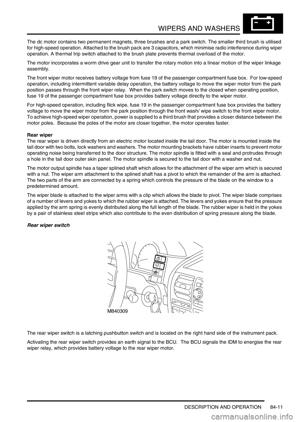
The rear wiper switch is a latching pushbutton switch and is located on the right hand side of the instrument pack.
Activating the rear wiper switch provides an earth signal to the BCU. The BCU signals the IDM to energise the rear
wiper relay, which provides battery voltage to the rear wiper motor.
Page 1467 of 1672

LIGHTING
86-2-12 REPAIRS
Rheostat - panel lights dimmer
$% 86.65.37
Remove
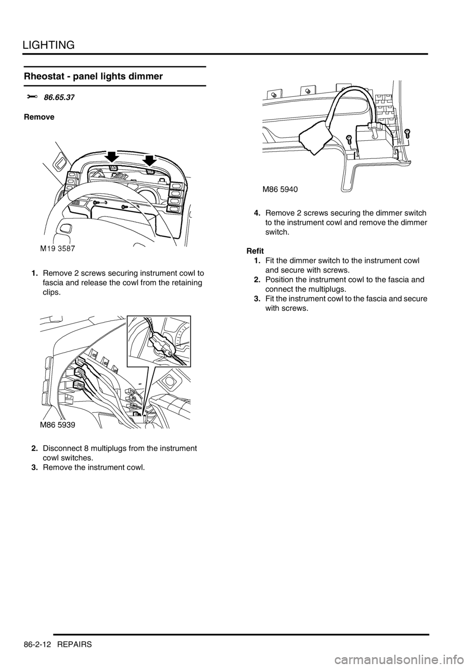
1.Remove 2 screws securing instrument cowl to
fascia and release the cowl from the retaining
clips.
2.Disconnect 8 multiplugs from the instrument
cowl switches.
3.Remove the instrument cowl.4.Remove 2 screws securing the dimmer switch
to the instrument cowl and remove the dimmer
switch.
Refit
1.Fit the dimmer switch to the instrument cowl
and secure with screws.
2.Position the instrument cowl to the fascia and
connect the multiplugs.
3.Fit the instrument cowl to the fascia and secure
with screws.
Page 1514 of 1672

ALARM SYSTEM AND HORN
DESCRIPTION AND OPERATION 86-4-5
Description
General
The anti-theft system deters the theft of the vehicle with both active and passive systems. The active systems monitor
the vehicle perimeter and, in some markets the vehicle interior, for intrusion. If the system detects intrusion, an alarm
sounds. The passive systems include a vehicle immobiliser as well as protection against intrusion through super
locking the doors. The vehicle is immobilised whenever the ignition key is removed from the ignition switch. Super
locking prevents the interior door handles from opening the doors. In addition, there are many features and functions
that enhance system operation.
It is possible to perform the various functions associated with the anti-theft system remotely. To accomplish this, the
handset generates a radio frequency when the lock button or unlock button is depressed. This signal is transmitted
to the Body Control Unit (BCU) via a receiver located in front of rear sunroof beneath the headlining. Precise alignment
of the handset to the receiver is not necessary. The approximate operating range between the handset and the
receiver is 10 metres (33 feet).
It is important to understand the configuration of the system on each particular vehicle. There are many
different combinations of features with dedicated operating modes. System configuration for each vehicle
can be determined using TestBook.
The anti-theft system is controlled centrally by the BCU, which is located below and behind the passenger glovebox.
A serial communication link communicates between the Intelligent Driver Module (IDM) located within the fusebox,
the BCU and the LED located in the instrument panel.
The state of the alarm is stored in the BCU. If the battery is disconnected while the alarm is armed, the alarm will be
triggered when the battery is reconnected.
NOTE: Disconnecting the battery while the alarm is armed triggers the alarm. Always disarm the alarm system before
disconnecting the battery.
The BCU also receives inputs from the following components:
lIgnition key in sensor.
lIgnition switch.
lFuel cut off switch.
lFuel flap release switch.
The BCU also interacts with the following components:
lStarter relay.
lVehicle horns.
lDirection indicators.
lFuel flap release actuator.
lCourtesy lamps.
Page 1526 of 1672

ALARM SYSTEM AND HORN
DESCRIPTION AND OPERATION 86-4-17
Internal locking
Internal locking allows the doors to be locked / unlocked from a central position using switches on the instrument
panel. The internal unlock switch will not operate if the vehicle is super locked.
Electric fuel flap release
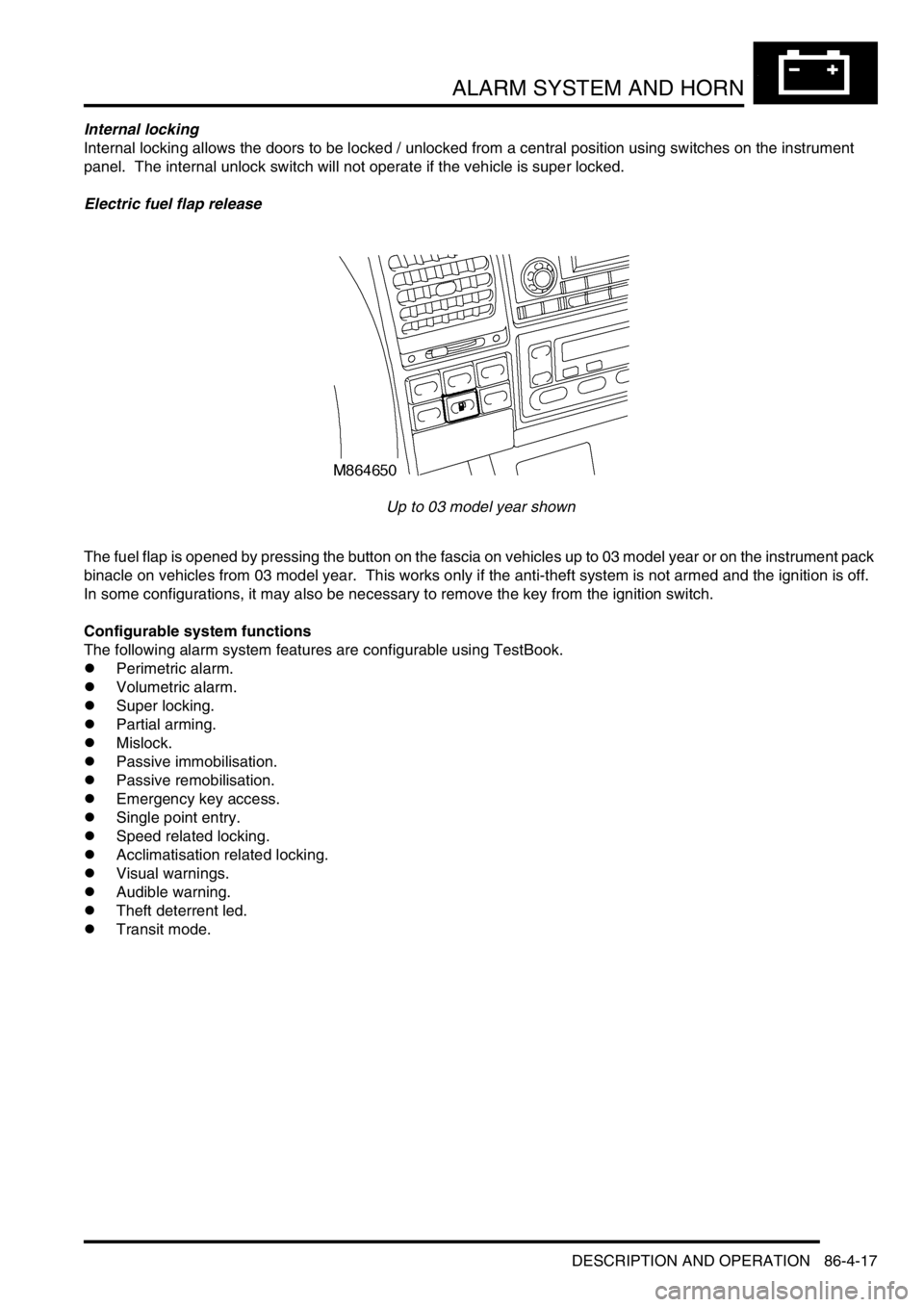
Up to 03 model year shown
The fuel flap is opened by pressing the button on the fascia on vehicles up to 03 model year or on the instrument pack
binacle on vehicles from 03 model year. This works only if the anti-theft system is not armed and the ignition is off.
In some configurations, it may also be necessary to remove the key from the ignition switch.
Configurable system functions
The following alarm system features are configurable using TestBook.
lPerimetric alarm.
lVolumetric alarm.
lSuper locking.
lPartial arming.
lMislock.
lPassive immobilisation.
lPassive remobilisation.
lEmergency key access.
lSingle point entry.
lSpeed related locking.
lAcclimatisation related locking.
lVisual warnings.
lAudible warning.
lTheft deterrent led.
lTransit mode.
Page 1531 of 1672

ALARM SYSTEM AND HORN
86-4-22 DESCRIPTION AND OPERATION
Speed related locking
For added protection the vehicle doors can automatically lock when the vehicle exceeds a specific road speed.
There are two configurations for speed related locking:
lSpeed related locking not active.
lSpeed related locking active.
Speed related locking causes the doors to automatically lock when the vehicle exceeds a speed of 4 mph (7 km/h).
When the ignition is switched off, the doors are automatically unlocked. Depressing the instrument panel mounted
central door unlocking switch disables the speed related locking for the duration of the journey.
Speed related locking only activates once per ignition cycle. If speed related locking activates and a door is then
unlocked, the door does not automatically re-lock.
In order for speed related locking to activate the following conditions must be met:
lAll doors unlocked.
lEngine running.
lVehicle speed greater than 4 mph (7 km/h).
Acclimatisation related locking
Acclimatisation related locking allows the engine to be started and then the vehicle locked with a spare key and left
unattended to allow the vehicle interior to reach the desired temperature.
There are two configurations for acclimatisation related locking:
lAcclimatisation related locking not active.
lAcclimatisation related locking active.
Once the engine is started, the vehicle is locked with a spare key at the driver's door while the engine is running.
During these conditions the alarm is not armed.
In order to activate acclimatisation related locking the following conditions must be met:
lEngine running.
lAll doors closed.
Visual warnings
The direction indicators serve as a visual indication when the alarm is triggered. The direction indicators are also used
as a visual indication during lock/unlock procedures.
There are three configurations of alarm armed/disarmed indication:
lNo direction indicators on, alarm armed/disarmed/trigger.
lDirection indicators on, alarm trigger only.
lDirection indicators on, alarm armed/disarmed/trigger.
Dependent on system configuration the direction indicators flash one short pulse to confirm that the alarm is armed
and flash two short pulses to confirm that the vehicle is super locked. If the alarm is triggered the direction indicators
operate in phase with the audible warning. When the alarm is disarmed, the direction indicators flash one long pulse.
Audible warning
An audible warning device is used to indicate that the alarm has been triggered, or a mislock has occurred, or an EKA
request has occurred, or the EKA code has been entered.
There are six audible warning configurations:
lNo sound (audible warnings disabled).
lAlarm sounder only.
lVehicle horn only.
lAlarm sounder and vehicle horn.
lBBUS only.
lAlarm sounder, vehicle horn and BBUS.
Page 1659 of 1672

INSTRUMENTS
88-32 DESCRIPTION AND OPERATION
Transmission high temperature warning lamp
The transmission high temperature warning lamp within the instrument pack utilises a red LED and a clear legend.
On vehicles fitted with automatic gearboxes, the transmission high temperature warning lamp is utilised to provide the
driver with a visible warning that the automatic gearbox oil has exceeded a normal operating temperature. The
warning lamp will extinguish if the gearbox oil returns back to normal operating temperature.
When the ignition is switched on, the instrument pack illuminates the LED to provide a self-check, providing there is
no fault it will remain illuminated for 3 seconds or until the ignition is switched off.
The power input for the LED is supplied by the instrument pack via fuse 13. The temperature sensor provides the
earth path to illuminate the transmission high temperature warning lamp.
The transmission high temperature warning lamp is controlled according to the voltage present on the temperature
sensor to instrument panel earth path:
l< 1.8 volts = warning lamp on.
l> 7.7 volts = warning lamp off.