2002 LAND ROVER DISCOVERY alternator belt
[x] Cancel search: alternator beltPage 304 of 1672

ENGINE - V8
OVERHAUL 12-2-61
9.Remove cylinder head gasket.
CAUTION: Support both ends of cylinder
head on blocks of wood.
Inspect
1.Clean mating faces of cylinder block and head
using suitable gasket removal spray and a
plastic scraper, ensure that bolt holes in block
are clean and dry.
CAUTION: Do not use a metal scraper or
machined surfaces may be damaged.
2.Check head and block faces for warping and
pitting.
lMaximum cylinder head warp = 0.05 mm
(0.002 in).
Note: Cylinder head can be refaced to 0.50
mm (0.02 in) maximum below head height –
See cylinder head overhaul.Reassembly
1.Fit cylinder head gasket with the word TOP
uppermost.
CAUTION: Gaskets must be fitted dry.
2.Carefully fit cylinder head and locate on
dowels.
3.Lightly lubricate new cylinder head bolt threads
with clean engine oil.
4.Noting that bolts 1, 3 and 5 are longer than the
remainder, fit bolts and tighten in the sequence
shown to 20 Nm (15 lbf.ft) then turn through 90
°, then a further 90 °. CAUTION: Do not
tighten bolts 180
° in one operation.
5.Clean the push rods, Lubricate ends of push
rods with clean engine oil, and fit in their
removed order.
6.Clean bases of rocker pillars and mating faces
on cylinder head.
7.Clean contact surfaces on rockers, valves and
push rods.
8.Lubricate contact surfaces and rocker shaft
with clean engine oil.
9.Fit rocker shaft assembly and engage push
rods.
10.Fit rocker shaft bolts and progressively tighten
to 40 Nm (30 lbf.ft).
11.Connect ht leads to spark plugs in their correct
fitted order.
12. RH cylinder head: Position alternator
mounting bracket, fit bolts and tighten to 40 Nm
(30 lbf.ft).
13. RH cylinder head: Fit auxiliary drive belt
tensioner.
14.Fit inlet manifold gasket.
+ ENGINE - V8, OVERHAUL, Gasket -
inlet manifold.
Page 530 of 1672

ENGINE MANAGEMENT SYSTEM - V8
REPAIRS 18-2-73
5.Remove 2 nuts and release ECM from studs
and location on 'A' post lower panel.
6.Lower ECM into footwell and disconnect 5
multiplugs.
7.Remove ECM.
Refit
1.Position new ECM and connect multiplugs.
2.Fit ECM and secure with nuts.
3.Fit lower trim panel to 'A' post and secure with
fixings.
4.Fit diagnostic socket to closing panel, fit closing
panel and secure with fixings.
5.Connect battery earth lead.
6.Fit battery cover and secure with fixings.
7.Programme ECM and reset adaptions using
TestBook.
Sensor - engine coolant temperature
(ECT)
$% 18.30.10
Remove
1.Release turnbuckles and remove battery cover.
2.Disconnect battery earth lead.
3.Remove auxiliary drive belt.
+ CHARGING AND STARTING,
REPAIRS, Belt - auxiliary drive.
4.Remove 2 bolts securing alternator, release
alternator from support bracket and position
aside.
Page 531 of 1672

ENGINE MANAGEMENT SYSTEM - V8
18-2-74 REPAIRS
5.Disconnect multiplug from ECT sensor.
6.Remove sensor from inlet manifold and discard
sealing washer.
Refit
1.Clean sealant from threads in manifold.
2.Apply Loctite 577 to sensor threads.
3.Fit new sealing washer to ECT sensor and
tighten sensor to 10 Nm (7 lbf.ft).
4.Connect multiplug to ECT sensor.
5.Position alternator, fit bolts and tighten to 45
Nm (33 lbf.ft).
6.Fit auxiliary drive belt.
+ CHARGING AND STARTING,
REPAIRS, Belt - auxiliary drive.
7.Top up cooling system.
8.Connect battery earth lead.
9.Fit battery cover and secure with fixings.
Sensor - crankshaft position (CKP)
$% 18.30.12
Remove
1.Release fixings and remove battery cover.
2.Disconnect battery earth lead.
3.Raise front of vehicle.
WARNING: Do not work on or under a
vehicle supported only by a jack. Always
support the vehicle on safety stands.
4.Release fixings and remove underbelly panel.
5.Release CKP sensor multiplug from bracket.
6.Remove 2 bolts securing CKP sensor heat
shield and position aside.
7.Remove 2 nuts securing CKP sensor, remove
2 spacers, CKP sensor and sensor mounting.
8.Disconnect CKP sensor multiplug from engine
harness.
Refit
1.Ensure all components are clean.
2.Connect CKP sensor multiplug to engine
harness.
3.Fit sensor mounting, CKP sensor, 2 spacers
and tighten CKP sensor retaining nuts to 6 Nm
(5 lbf.ft).
Page 644 of 1672

MANIFOLDS AND EXHAUST SYSTEMS - V8
REPAIRS 30-2-15
Refit
1.Clean old RTV sealant from cylinder head and
cylinder block notches.
2.Clean mating faces of cylinder block, cylinder
head and inlet manifold.
3.Apply RTV sealant to cylinder head and
cylinder block notches.
4.Fit new gasket seals, ensuring ends engage
correctly in notches.
5.Fit new inlet manifold gasket.
6.Position gasket clamps and fit bolts, but do not
tighten at this stage.
7.Position inlet manifold to engine. Fit manifold
bolts and, working in the sequence shown,
tighten bolts initially to 10 Nm (7 lbf.ft) then to
51 Nm (38 lbf.ft).
8.Tighten gasket clamp bolts to 18 Nm (13 lbf.ft).
9.Connect fuel pipe.
10.Clean top hose outlet pipe mating faces.
11.Fit new 'O' ring to outlet pipe.
12.Position outlet pipe, fit bolts and tighten to 22
Nm (16 lbf.ft).
13.Position alternator, fit bolts and tighten to 45
Nm (33 lbf.ft).
14.Position PAS pump to auxiliary housing and
locate housing on engine. Fit bolts and tighten
to 40 Nm (30 lbf.ft).
15.Fit and tighten auxiliary housing nut to 10 Nm (7
lbf.ft).
16.Fit bolts securing PAS pump and tighten to 22
Nm (16 lbf.ft). 17.Position oil cooling pipe bracket fit bolt and
tighten to 22 Nm (16 lbf.ft).
18.Fit and tighten PAS pump high pressure pipe.
19.Position jockey pulley and tighten bolt to 50 Nm
(37 lbf.ft).
20.Clean PAS pump pulley mating faces.
21.Position PAS pump pulley, fit bolts and tighten
to 22 Nm (16 lbf.ft).
22.Clean ACE pump dowels and dowel holes.
23.Position ACE pump, fit bolts and tighten to 22
Nm (16 lbf.ft).
24.Fit auxiliary drive belt.
+ CHARGING AND STARTING,
REPAIRS, Belt - auxiliary drive.
25.Secure injector harness and connect injector
multiplugs.
26.Position top hose and secure clips.
27.Fit rocker covers.
l
+ ENGINE - V8, REPAIRS, Gasket
- rocker cover - LH.
l
+ ENGINE - V8, REPAIRS, Gasket
- rocker cover - RH.
28.Check and top up PAS fluid
Page 1055 of 1672

BRAKES
70-10 DESCRIPTION AND OPERATION
Vacuum pump (diesel models only)
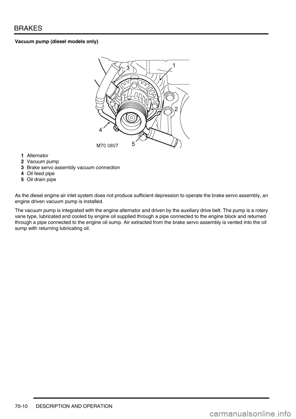
1Alternator
2Vacuum pump
3Brake servo assembly vacuum connection
4Oil feed pipe
5Oil drain pipe
As the diesel engine air inlet system does not produce sufficient depression to operate the brake servo assembly, an
engine driven vacuum pump is installed.
The vacuum pump is integrated with the engine alternator and driven by the auxiliary drive belt. The pump is a rotary
vane type, lubricated and cooled by engine oil supplied through a pipe connected to the engine block and returned
through a pipe connected to the engine oil sump. Air extracted from the brake servo assembly is vented into the oil
sump with returning lubricating oil.
Page 1087 of 1672

BRAKES
70-42 REPAIRS
Vacuum pump - servo
$% 70.50.19
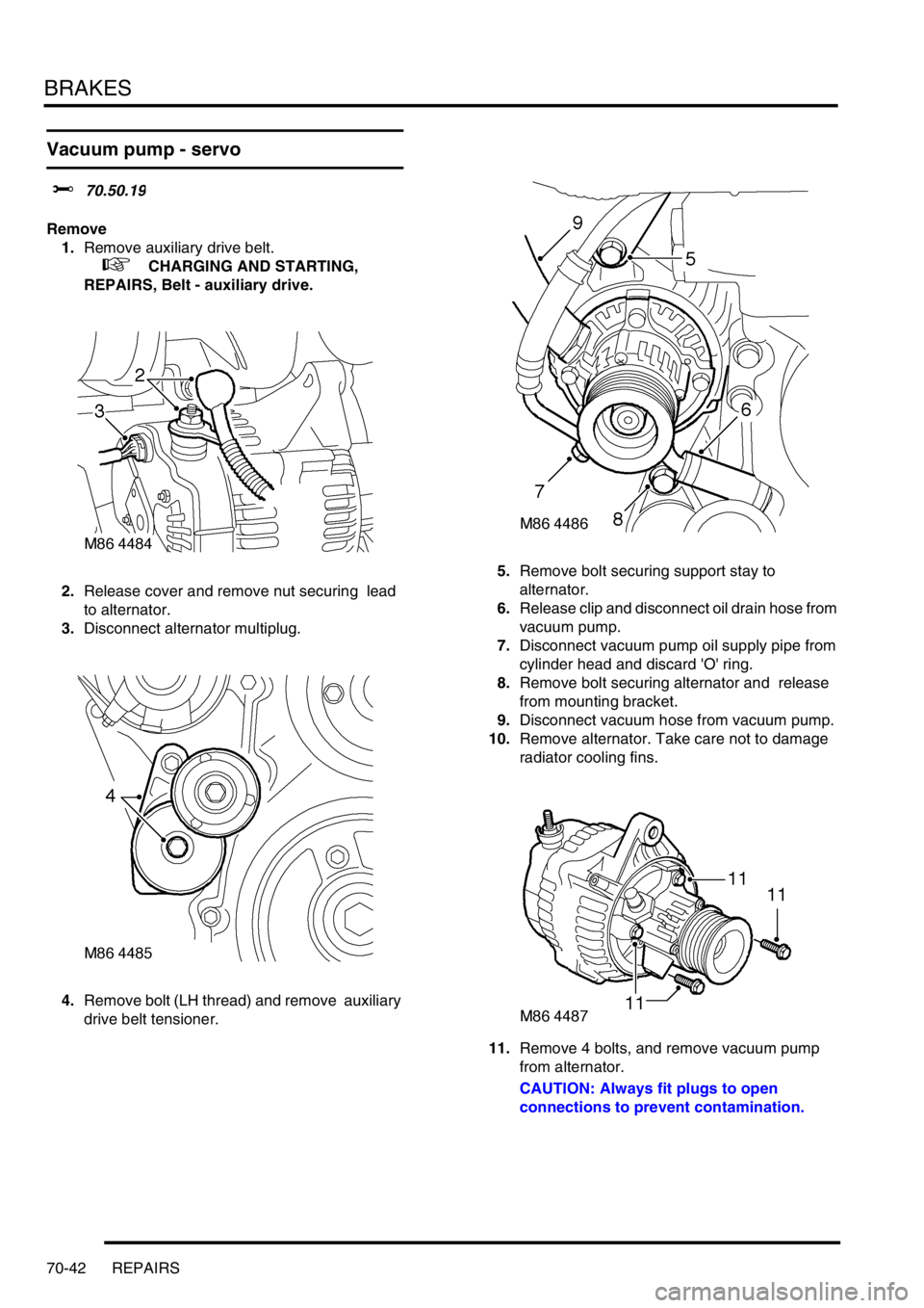
Remove
1.Remove auxiliary drive belt.
+ CHARGING AND STARTING,
REPAIRS, Belt - auxiliary drive.
2.Release cover and remove nut securing lead
to alternator.
3.Disconnect alternator multiplug.
4.Remove bolt (LH thread) and remove auxiliary
drive belt tensioner. 5.Remove bolt securing support stay to
alternator.
6.Release clip and disconnect oil drain hose from
vacuum pump.
7.Disconnect vacuum pump oil supply pipe from
cylinder head and discard 'O' ring.
8.Remove bolt securing alternator and release
from mounting bracket.
9.Disconnect vacuum hose from vacuum pump.
10.Remove alternator. Take care not to damage
radiator cooling fins.
11.Remove 4 bolts, and remove vacuum pump
from alternator.
CAUTION: Always fit plugs to open
connections to prevent contamination.
Page 1088 of 1672

BRAKES
REPAIRS 70-43
Refit
1.Clean mating faces of alternator and vacuum
pump.
2.Fit vacuum pump to alternator and tighten
bolts to 8 Nm (6 lbf.ft).
3.Position alternator to engine and connect
multiplug.
4.Connect vacuum hose and oil drain hose to
vacuum pump and secure clips.
5.With assistance align alternator to mounting
bracket and fit but do not tighten bolt.
6.Fit bolt securing support stay to alternator and
tighten to 25 Nm (18 lbf.ft) .
7.Tighten bolt securing alternator to mounting
bracket to 45 Nm (33 lbf.ft).
8.Using new 'O' ring, connect oil supply pipe to
cylinder head and tighten to 10 Nm (7 lbf.ft).
9.Connect lead to alternator and tighten nut to 6
Nm (4.4 lbf.ft).
10.Fit auxiliary drive belt tensioner and tighten bolt
to 50 Nm (37 lbf.ft).
11.Fit auxiliary drive belt.
+ CHARGING AND STARTING,
REPAIRS, Belt - auxiliary drive.
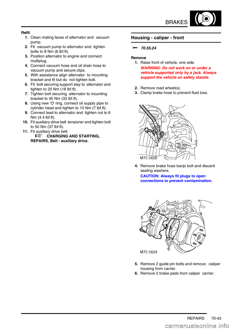
Housing - caliper - front
$% 70.55.24
Remove
1.Raise front of vehicle, one side.
WARNING: Do not work on or under a
vehicle supported only by a jack. Always
support the vehicle on safety stands.
2.Remove road wheel(s).
3.Clamp brake hose to prevent fluid loss.
4.Remove brake hose banjo bolt and discard
sealing washers.
CAUTION: Always fit plugs to open
connections to prevent contamination.
5.Remove 2 guide pin bolts and remove caliper
housing from carrier.
6.Remove 2 brake pads from caliper carrier.
Page 1286 of 1672

PANEL REPAIRS
REPAIRS 77-2-37
Sill outer assembly
Remove
1.Disconnect both battery leads, negative lead
first.
2.Disconnect leads/multiplug from alternator.
3.Remove RH or LH front wing.
+ EXTERIOR FITTINGS, REPAIRS,
Wing - front - up to 03MY.
4.Remove RH or LH front door.
+ DOORS, REPAIRS, Door - front.
5.Remove RH or LH rear door.
+ DOORS, REPAIRS, Door - rear.
6.Remove RH or LH sill finisher.
7.Remove RH or LH 'A' post inner lower
finishers.
8.Remove RH or LH front seat.
+ SEATS, REPAIRS, Seat - front.
9. LH side: Remove power amplifier and EAT
ECU.
+ IN CAR ENTERTAINMENT,
REPAIRS, Amplifier - power.
10. RH side: Remove CD autochanger.
+ IN CAR ENTERTAINMENT,
REPAIRS, CD autochanger.
11.Remove rear seats.
+ SEATS, REPAIRS, Seat - rear.
12.Remove RH or LH front seat belt.
+ RESTRAINT SYSTEMS, REPAIRS,
Seat belt - front.
13.Remove tread plates from front and rear door
apertures.
14.Release carpet and position aside.
15.Remove front and rear door aperture seals.
16.Release relevant wiring from 'A' post, 'B/C' post
and sill areas, and position aside.
17.Remove loadspace lower trim casing.
+ INTERIOR TRIM COMPONENTS,
REPAIRS, Trim casing - side - loadspace.
18. RH side: Remove lower ACE accelerometer.
+ FRONT SUSPENSION, REPAIRS,
Accelerometer - ACE - lower.
19. LH side: Remove SLS air compressor unit.
+ REAR SUSPENSION, REPAIRS,
Compressor unit - air - SLS.
20. Models with rear A/C: Recover refrigerant
from A/C system and remove A/C pipes from
LH sill.
+ AIR CONDITIONING, REFRIGERANT
RECOVERY, RECYCLING AND
RECHARGING, Refrigerant recovery,
recycling and recharging.
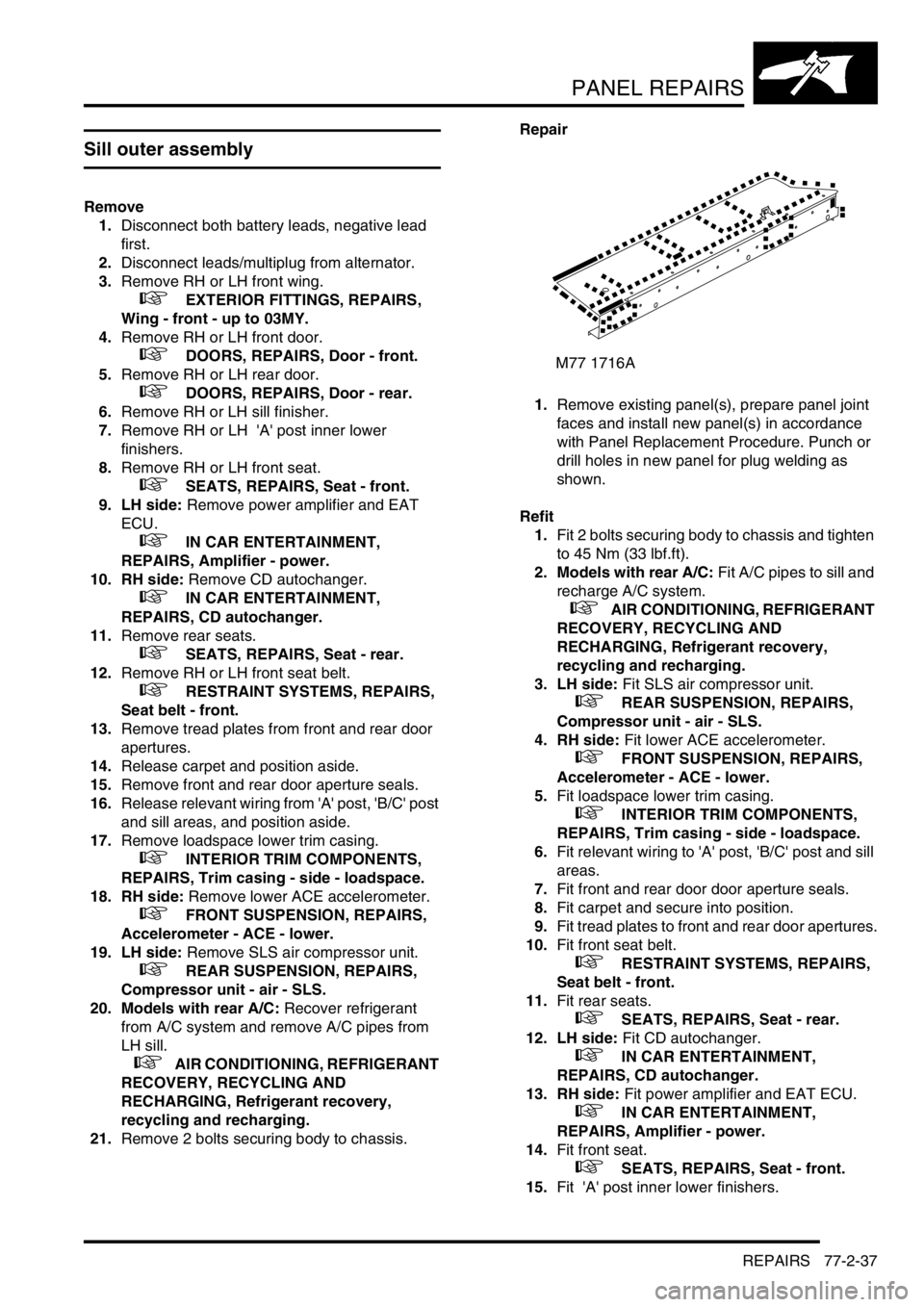
21.Remove 2 bolts securing body to chassis.Repair
1.Remove existing panel(s), prepare panel joint
faces and install new panel(s) in accordance
with Panel Replacement Procedure. Punch or
drill holes in new panel for plug welding as
shown.
Refit
1.Fit 2 bolts securing body to chassis and tighten
to 45 Nm (33 lbf.ft).
2. Models with rear A/C: Fit A/C pipes to sill and
recharge A/C system.
+ AIR CONDITIONING, REFRIGERANT
RECOVERY, RECYCLING AND
RECHARGING, Refrigerant recovery,
recycling and recharging.
3. LH side: Fit SLS air compressor unit.
+ REAR SUSPENSION, REPAIRS,
Compressor unit - air - SLS.
4. RH side: Fit lower ACE accelerometer.
+ FRONT SUSPENSION, REPAIRS,
Accelerometer - ACE - lower.
5.Fit loadspace lower trim casing.
+ INTERIOR TRIM COMPONENTS,
REPAIRS, Trim casing - side - loadspace.
6.Fit relevant wiring to 'A' post, 'B/C' post and sill
areas.
7.Fit front and rear door door aperture seals.
8.Fit carpet and secure into position.
9.Fit tread plates to front and rear door apertures.
10.Fit front seat belt.
+ RESTRAINT SYSTEMS, REPAIRS,
Seat belt - front.
11.Fit rear seats.
+ SEATS, REPAIRS, Seat - rear.
12. LH side: Fit CD autochanger.
+ IN CAR ENTERTAINMENT,
REPAIRS, CD autochanger.
13. RH side: Fit power amplifier and EAT ECU.
+ IN CAR ENTERTAINMENT,
REPAIRS, Amplifier - power.
14.Fit front seat.
+ SEATS, REPAIRS, Seat - front.
15.Fit 'A' post inner lower finishers.
M77 1716A