Page 532 of 1672
ENGINE MANAGEMENT SYSTEM - V8
REPAIRS 18-2-75
4.Fit CKP sensor heat shield and secure with
bolts.
5.Fit underbelly panel and secure with fixings.
6.Remove stand(s) and lower vehicle.
7.Connect battery earth lead.
8.Fit battery cover and secure the fixings.
9.Reset adaptions using TestBook.
Sensor - radiator temperature
$% 18.30.20
Remove
1.Disconnect battery earth lead.
2.Position container to collect coolant spillage.
3.Disconnect multiplug from sensor.
4.Remove sensor and discard sealing washer.
Refit
1.Fit new sealing washer to sensor.
2.Fit and tighten sensor.
3.Connect multiplug to sensor.
4.Refill cooling system.
5.Connect battery earth lead.
Page 533 of 1672

ENGINE MANAGEMENT SYSTEM - V8
18-2-76 REPAIRS
Sensor - camshaft position (CMP)
$% 18.30.24
Remove
1.Release fixings and remove battery cover.
2.Disconnect battery earth lead.
3.Raise front of vehicle.
WARNING: Do not work on or under a
vehicle supported only by a jack. Always
support the vehicle on safety stands.
4.Release fixings and remove underbelly panel.
5.Remove engine oil filter.
+ ENGINE - V8, REPAIRS, Filter - oil.
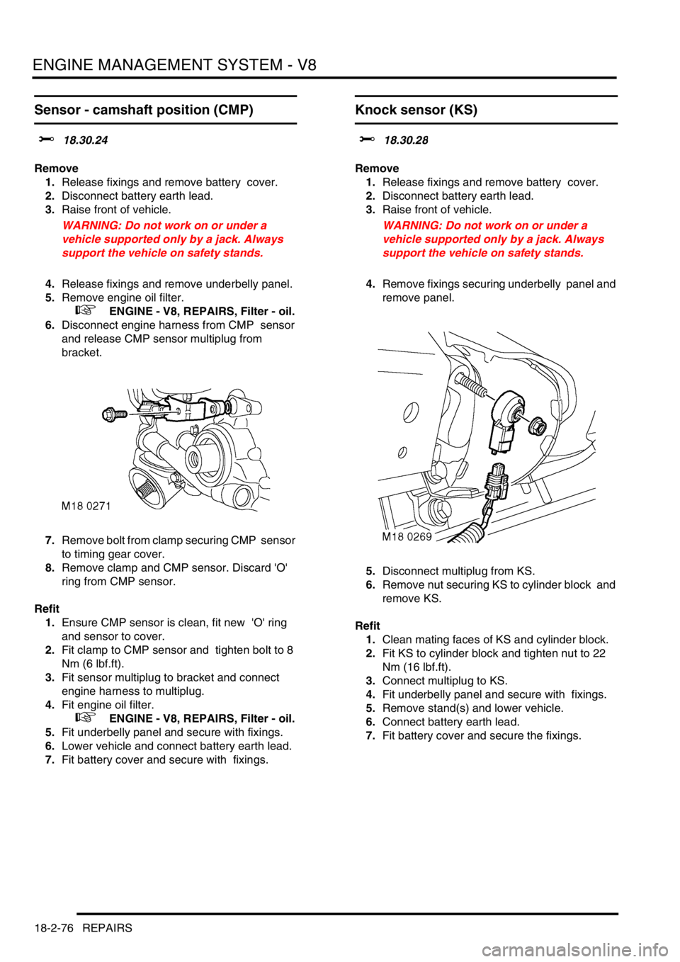
6.Disconnect engine harness from CMP sensor
and release CMP sensor multiplug from
bracket.
7.Remove bolt from clamp securing CMP sensor
to timing gear cover.
8.Remove clamp and CMP sensor. Discard 'O'
ring from CMP sensor.
Refit
1.Ensure CMP sensor is clean, fit new 'O' ring
and sensor to cover.
2.Fit clamp to CMP sensor and tighten bolt to 8
Nm (6 lbf.ft).
3.Fit sensor multiplug to bracket and connect
engine harness to multiplug.
4.Fit engine oil filter.
+ ENGINE - V8, REPAIRS, Filter - oil.
5.Fit underbelly panel and secure with fixings.
6.Lower vehicle and connect battery earth lead.
7.Fit battery cover and secure with fixings.
Knock sensor (KS)
$% 18.30.28
Remove
1.Release fixings and remove battery cover.
2.Disconnect battery earth lead.
3.Raise front of vehicle.
WARNING: Do not work on or under a
vehicle supported only by a jack. Always
support the vehicle on safety stands.
4.Remove fixings securing underbelly panel and
remove panel.
5.Disconnect multiplug from KS.
6.Remove nut securing KS to cylinder block and
remove KS.
Refit
1.Clean mating faces of KS and cylinder block.
2.Fit KS to cylinder block and tighten nut to 22
Nm (16 lbf.ft).
3.Connect multiplug to KS.
4.Fit underbelly panel and secure with fixings.
5.Remove stand(s) and lower vehicle.
6.Connect battery earth lead.
7.Fit battery cover and secure the fixings.
Page 534 of 1672
ENGINE MANAGEMENT SYSTEM - V8
REPAIRS 18-2-77
Air cleaner assembly
$% 19.10.01
Remove
1.Remove 2 nuts securing air intake ducting.
2.Remove both parts of air intake ducting.
3.Release 2 clips securing MAF sensor, release
2 clips securing air intake hose.
Note: Pre 03 MY air intake hose illustrated.
4.Release air intake hose and position aside. 5.Remove and discard MAF sensor 'O' ring.
6.Release air cleaner assembly from 3
grommets and remove assembly.
Refit
1.Position air cleaner assembly and secure in
grommets.
2.Fit new 'O' ring to MAF sensor.
3.Position air intake hose, secure MAF sensor
clips and tighten intake hose clips.
CAUTION: Ensure MAF sensor 'O' ring is
not displaced during fitting.
4.Fit air intake ducting and secure with nuts.
Page 535 of 1672
ENGINE MANAGEMENT SYSTEM - V8
18-2-78 REPAIRS
Element - air filter
$% 19.10.10
Remove
1.Release 2 clips and disconnect MAF sensor
from air filter cover, remove and discard 'O'
ring.
2.Release 2 clips and remove cover from air
filter.
3.Remove air filter element.
Refit
1.Clean air filter body and cover.
2.Fit new air filter element.
3.Position air cleaner cover and secure clips.
CAUTION: Ensure clips are correctly
located on cover.
4.Fit a new MAF sensor 'O' ring, position MAF
sensor and secure clips.
CAUTION: Ensure 'O' ring is not displaced
during fitting.
Cable - throttle
$% 19.20.06
Remove
1.Release 3 fasteners and remove drivers side
closing panel and move aside.
2.Release inner cable from throttle pedal.
3.Release outer cable from bulkhead.
Page 536 of 1672

ENGINE MANAGEMENT SYSTEM - V8
REPAIRS 18-2-79
4.Release outer cable from clip, loosen lock nuts
and remove outer cable from abutment
bracket.
5.Release inner cable from operating lever and
remove cable.
Refit
1.Position cable, secure to bulkhead and
connect inner cable to throttle pedal.
2.Position inner cable to operating lever and
connect outer cable to abutment bracket and
retaining clip.
3.Position closing panel and secure fasteners.
4.Adjust throttle cable.
+ ENGINE MANAGEMENT SYSTEM -
V8, ADJUSTMENTS, Cable - throttle.
Sensor - Mass Air Flow (MAF)
$% 19.22.25
Remove
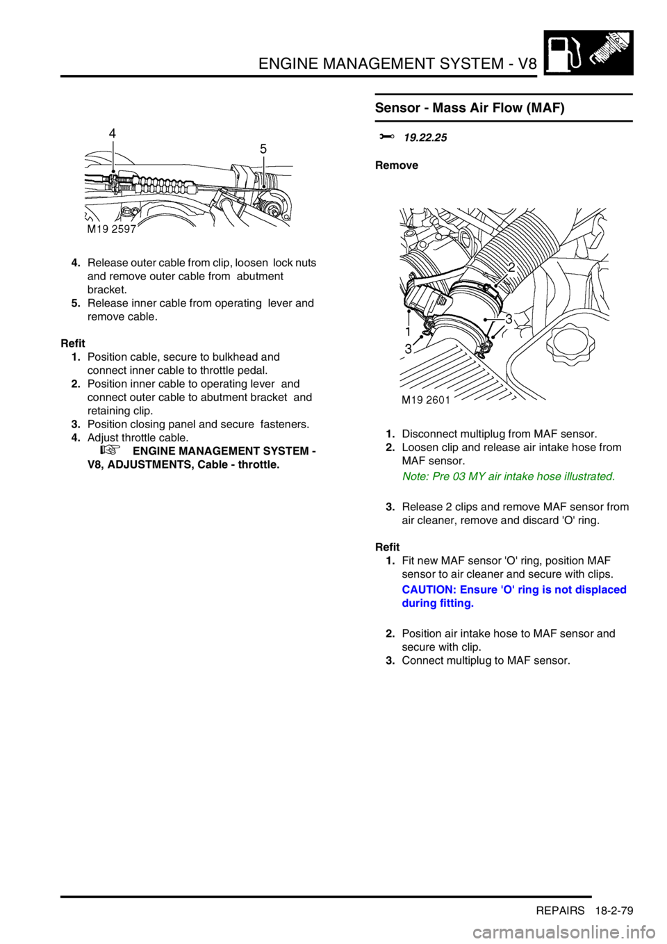
1.Disconnect multiplug from MAF sensor.
2.Loosen clip and release air intake hose from
MAF sensor.
Note: Pre 03 MY air intake hose illustrated.
3.Release 2 clips and remove MAF sensor from
air cleaner, remove and discard 'O' ring.
Refit
1.Fit new MAF sensor 'O' ring, position MAF
sensor to air cleaner and secure with clips.
CAUTION: Ensure 'O' ring is not displaced
during fitting.
2.Position air intake hose to MAF sensor and
secure with clip.
3.Connect multiplug to MAF sensor.
Page 539 of 1672
ENGINE MANAGEMENT SYSTEM - V8
18-2-82 REPAIRS
Sensor - throttle position (TP)
$% 19.22.49
Remove
1.Disconnect multiplug from TP sensor.
2.Remove 2 screws securing TP sensor to
throttle body.
3.Remove TP sensor and discard 'O' ring.
Refit
1.Clean TP sensor and throttle body mating
faces.
2.Using a new 'O' ring, position TP sensor. Fit
screws and tighten to 2.2 Nm (1.6 lbf.ft).
3.Connect multiplug to TP sensor.
Valve - idle air control (IACV)
$% 19.22.54
Remove
1.Disconnect multiplug from IACV.
2.Loosen 2 clips securing air hoses and release
hoses.
3.Remove 2 screws securing IACV to inlet
manifold.
4.Collect clamps and remove IACV.
Refit
1.Position IACV to inlet manifold, locate clamps,
fit screws and tighten to 8 Nm (6 lbf.ft).
2.Position air hoses to IACV and secure clips.
3.Connect multiplug to IACV.
Page 546 of 1672
FUEL DELIVERY SYSTEM - TD5
DESCRIPTION AND OPERATION 19-1-1
FUEL DELIVERY SYST EM - Td5 DESCRIPTION AND OPERAT ION
Fuel delivery system component
location
A = Pre EU3 models
1HP stage
2LP stage
3Filters
4Jet pump
5Fuel pump and fuel gauge sender assembly
6LP return connection
7LP feed connection
8HP feed connection9Air bleed connection
10Fuel filter
11Water sensor
12Fuel cooler
13Fuel pressure regulator (EU3 models)
14Electronic unit injectors
15Fuel pressure regulator (pre EU3 models)
16Electronic unit injectors
Page 548 of 1672

FUEL DELIVERY SYSTEM - TD5
DESCRIPTION AND OPERATION 19-1-3
Description
General
The fuel delivery system comprises a fuel tank, fuel pump, fuel pressure regulator, five injectors and a fuel filter. The
system is controlled by the Engine Control Module (ECM) which energises the fuel pump relay and controls the
operation and timing of each injector solenoid.
Unlike other Diesel engines, the Td5 engine has no injection pump. The diesel direct injection system receives fuel
at pressure from a two stage fuel pump located in the fuel tank. The system incorporates a fuel return to the fuel pump,
via a fuel cooler attached to the inlet manifold and a fuel filter. A fuel pressure regulator is located in a housing on the
rear of the cylinder head. The regulator maintains the fuel delivered to the injectors at a constant pressure and returns
excess fuel back to the fuel filter and pump via the fuel cooler.
A fuel filter is positioned on the chassis to the right of the fuel tank. The fuel feed and return to and from the engine
passes through the filter. The filter also incorporates a water sensor which illuminates a warning lamp in the
instrument pack.
A moulded fuel tank is located at the rear underside of the vehicle between the chassis longitudinals. The tank
provides the attachment for the fuel pump and fuel gauge sender unit which is located inside the tank.
Fuel tank and breather
The fuel tank and breather system is a major part of the fuel delivery system. The fuel tank and breathers are located
at the rear of the vehicle between the chassis longitudinals.
Fuel tank
The moulded fuel tank is made from High Molecular Weight (HMW) High Density Polyethylene (HDPE). The diesel
tank is manufactured using a proportion of recycled plastic.
The tank is retained in position by a metal cradle which is secured to the chassis with two nut plates and bolts at the
rear and a stud plate and two nuts at the front. A strap above the tank is bolted to the chassis and restrains the tank
from moving upwards. The fuel tank has useable capacity of approximately 95 litres (25 US Gallons).
An aperture in the top surface of the tank allows for the fitment of the fuel pump and fuel gauge sender unit which is
retained with a locking ring.
A reflective metallic covering is attached to the tank with two scrivets to shield the tank from heat generated by the
exhaust system.
The fuel filler is located in the right hand rear quarter panel, behind an access flap. The flap is opened electrically
using a switch on the fascia which operates a release solenoid.
The filler is closed by a threaded plastic cap which screws into the filler neck. The cap has a ratchet mechanism to
prevent overtightening and seals against the filler neck to prevent the escape of fuel vapour. The filler cap has a valve
which relieves fuel pressure to atmosphere at approximately 0.12 to 0.13 bar (1.8 to 2.0 lbf.in
2) and opens in the
opposite direction at approximately 0.04 bar (0.7 lbf.in2) vacuum.
A moulded filler tube, made from HMW HDPE, connects the filler to the tank via a flexible hose. The filler tube is
connected at its top end behind the filler flap.