Page 1583 of 1672

HARNESSES
86-7-12 REPAIRS
24.Remove bolt securing harness clip to LH side of
engine.
25.Disconnect camshaft sensor and oil pressure
switch multiplugs.
26.Remove engine harness. Refit
1.Position engine harness around engine.
2.Connect oil pressure switch and camshaft
sensor multiplugs.
3.Fit and tighten bolt securing harness to LH side
of engine.
4.Connect both knock sensor multiplugs.
5.Connect battery cable and solenoid cable to
starter motor.
6.Position starter heat shield and secure with
bolt.
7.Clean exhaust flange mating faces, using a
new gasket align exhaust fit nuts and tighten to
60 Nm (44 lbf.ft).
8.Remove stand(s) and lower vehicle.
9.Position harness into footwell and secure
grommet.
10.Connect ECM multiplugs.
11.Position toe board and secure with trim fixings.
12.Connect engine harness to main harness
multiplug and secure earth lead.
13.Connect EVAP solenoid multiplug.
14.Connect both fuse box multiplugs.
15.Position starter lead to fuse box and secure
screw.
16.Fit fuse box cover.
17.Position battery positive lead to battery and
secure nut.
18.Secure harness to coolant rail.
19.Position alternator cables and tighten terminal
B+ to 18 Nm (13 lbf.ft) and terminal D+ to 5 Nm
(3.7 lbf.ft)
20.Connect coolant temperature sensor multiplug.
21.Connect A/C compressor multiplug.
22.Secure harness clip to rear of LH cylinder head.
23.Connect CKP sensor multiplug.
24.Secure injector harness and connect injector
multiplugs.
25.Connect coil multiplugs.
26.Connect and secure HS
2O sensor multiplug
27.Fit upper inlet manifold.
+ MANIFOLDS AND EXHAUST
SYSTEMS - V8, REPAIRS, Gasket - inlet
manifold - upper - Without Secondary Air
Injection.
28.Connect battery earth lead.
Page 1585 of 1672
HARNESSES
86-7-14 REPAIRS
10.Remove nut and disconnect battery lead from
starter solenoid.
11.Disconnect Lucar from starter solenoid.
12.Disconnect multiplug from CKP sensor. 13.Disconnect multiplug from fuel temperature
sensor.
14.Release harness clip from coolant pipe.
Page 1586 of 1672

HARNESSES
REPAIRS 86-7-15
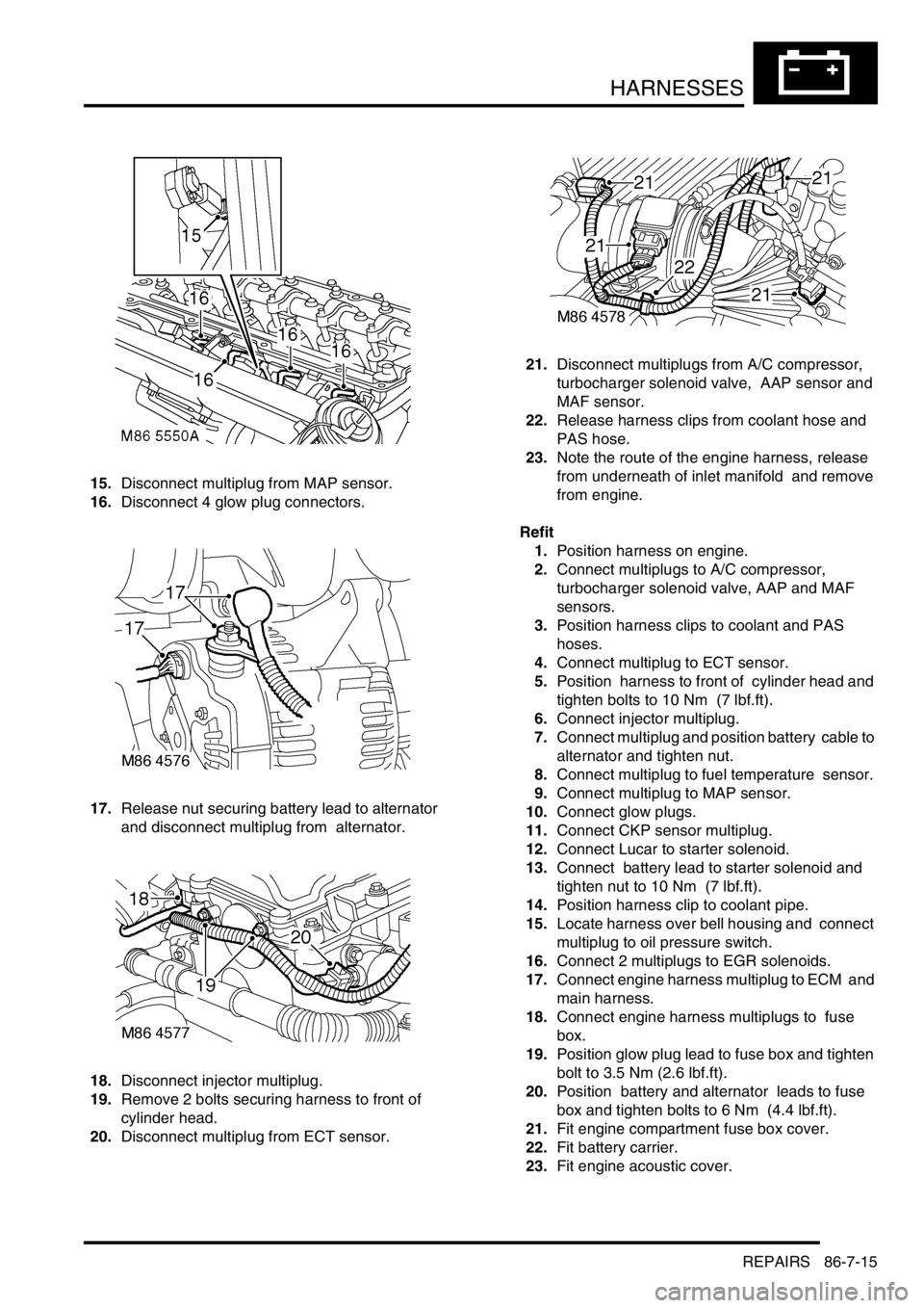
15.Disconnect multiplug from MAP sensor.
16.Disconnect 4 glow plug connectors.
17.Release nut securing battery lead to alternator
and disconnect multiplug from alternator.
18.Disconnect injector multiplug.
19.Remove 2 bolts securing harness to front of
cylinder head.
20.Disconnect multiplug from ECT sensor. 21.Disconnect multiplugs from A/C compressor,
turbocharger solenoid valve, AAP sensor and
MAF sensor.
22.Release harness clips from coolant hose and
PAS hose.
23.Note the route of the engine harness, release
from underneath of inlet manifold and remove
from engine.
Refit
1.Position harness on engine.
2.Connect multiplugs to A/C compressor,
turbocharger solenoid valve, AAP and MAF
sensors.
3.Position harness clips to coolant and PAS
hoses.
4.Connect multiplug to ECT sensor.
5.Position harness to front of cylinder head and
tighten bolts to 10 Nm (7 lbf.ft).
6.Connect injector multiplug.
7.Connect multiplug and position battery cable to
alternator and tighten nut.
8.Connect multiplug to fuel temperature sensor.
9.Connect multiplug to MAP sensor.
10.Connect glow plugs.
11.Connect CKP sensor multiplug.
12.Connect Lucar to starter solenoid.
13.Connect battery lead to starter solenoid and
tighten nut to 10 Nm (7 lbf.ft).
14.Position harness clip to coolant pipe.
15.Locate harness over bell housing and connect
multiplug to oil pressure switch.
16.Connect 2 multiplugs to EGR solenoids.
17.Connect engine harness multiplug to ECM and
main harness.
18.Connect engine harness multiplugs to fuse
box.
19.Position glow plug lead to fuse box and tighten
bolt to 3.5 Nm (2.6 lbf.ft).
20.Position battery and alternator leads to fuse
box and tighten bolts to 6 Nm (4.4 lbf.ft).
21.Fit engine compartment fuse box cover.
22.Fit battery carrier.
23.Fit engine acoustic cover.
Page 1628 of 1672

INSTRUMENTS
DESCRIPTION AND OPERATION 88-1
INS TRUMENTS DESCRIPTION AND OPERAT ION
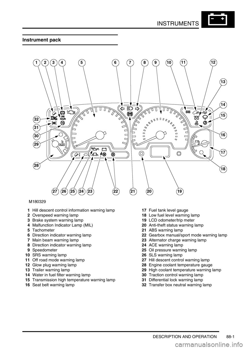
Instrument pack
1Hill descent control information warning lamp
2Overspeed warning lamp
3Brake system warning lamp
4Malfunction Indicator Lamp (MIL)
5Tachometer
6Direction indicator warning lamp
7Main beam warning lamp
8Direction indicator warning lamp
9Speedometer
10SRS warning lamp
11Off road mode warning lamp
12Glow plug warning lamp
13Trailer warning lamp
14Water in fuel filter warning lamp
15Transmission high temperature warning lamp
16Seat belt warning lamp17Fuel tank level gauge
18Low fuel level warning lamp
19LCD odometer/trip meter
20Anti-theft status warning lamp
21ABS warning lamp
22Gearbox manual/sport mode warning lamp
23Alternator charge warning lamp
24ACE warning lamp
25Oil pressure warning lamp
26SLS warning lamp
27Hill descent control warning lamp
28Engine coolant temperature gauge
29High coolant temperature warning lamp
30Traction control warning lamp
31Differential lock warning lamp
32Transfer box neutral warning lamp
Page 1632 of 1672

INSTRUMENTS
DESCRIPTION AND OPERATION 88-5
Description
General
The instrument pack consists of four analogue dials, four warning lamp packs and a Liquid Crystal Display (LCD)
odometer.
The four dials are used to indicate:
lRoad speed.
lEngine speed.
lFuel tank level.
lEngine coolant temperature.
The dials are driven by a microprocessor from information received from the serial communication link. Information
input is received as either:
lDigital.
lAnalogue.
lPulse train.
lPulse Width Modulation (PWM).
The LCD provides information for:
lOdometer.
lTrip distance.
lSelected gear (on vehicles fitted with an automatic gearbox).
A trip reset button is provided to zero the trip display, this button also allows the selection of "miles" or "kilometres"
for the display. A photocell controls the illumination of the LCD, maintaining contrast of the display during ambient light
changes.
Within the four warning lamp packs there are 28 lamps. A long life bulb illuminates the high beam warning lamp and
the rest of the warning lamps are illuminated by Light Emitting Diodes (LED's). All warning lamp legends are invisible
until lit. When lit the symbols are illuminated on a black background.
The warning lamps illuminate in one of four colours. The colour indicates the level of importance to the driver, as
follows:
lRed = warning.
lAmber = caution.
lGreen = system operative.
lBlue = main beam operative.
The first warning lamp pack is located in the top left-hand side of the instrument pack and contains the following
warning lamps:
lTraction control warning lamp.
lTransfer box in neutral warning lamp.
lDifferential lock warning lamp
lOverspeed warning lamp (activated for gulf market only).
lBrake system warning lamp.
lHill Descent Control (HDC) information warning lamp.
lMalfunction Indicator Lamp (MIL)/ SERVICE ENGINE SOON warning lamp.
The second warning lamp pack is located in the centre of the instrument pack and contains the following warning
lamps:
lDirection indicator warning lamps.
lHigh beam warning lamp.
lAnti-lock brake system warning lamp.
Page 1638 of 1672

INSTRUMENTS
DESCRIPTION AND OPERATION 88-11
Engine coolant temperature gauge
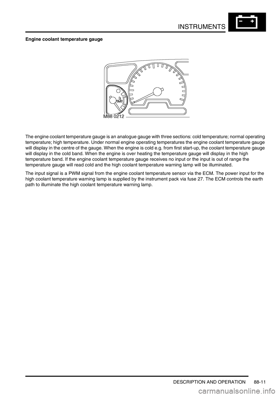
The engine coolant temperature gauge is an analogue gauge with three sections: cold temperature; normal operating
temperature; high temperature. Under normal engine operating temperatures the engine coolant temperature gauge
will display in the centre of the gauge. When the engine is cold e.g. from first start-up, the coolant temperature gauge
will display in the cold band. When the engine is over heating the temperature gauge will display in the high
temperature band. If the engine coolant temperature gauge receives no input or the input is out of range the
temperature gauge will read cold and the high coolant temperature warning lamp will be illuminated.
The input signal is a PWM signal from the engine coolant temperature sensor via the ECM. The power input for the
high coolant temperature warning lamp is supplied by the instrument pack via fuse 27. The ECM controls the earth
path to illuminate the high coolant temperature warning lamp.
Page 1646 of 1672

INSTRUMENTS
DESCRIPTION AND OPERATION 88-19
High engine coolant temperature warning lamp
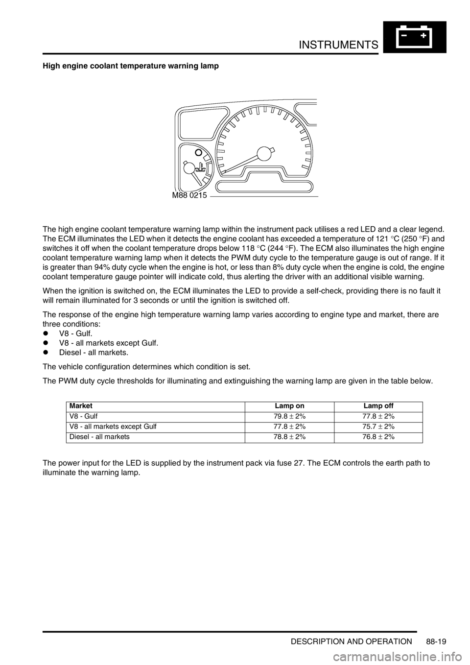
The high engine coolant temperature warning lamp within the instrument pack utilises a red LED and a clear legend.
The ECM illuminates the LED when it detects the engine coolant has exceeded a temperature of 121
°C (250 °F) and
switches it off when the coolant temperature drops below 118
°C (244 °F). The ECM also illuminates the high engine
coolant temperature warning lamp when it detects the PWM duty cycle to the temperature gauge is out of range. If it
is greater than 94% duty cycle when the engine is hot, or less than 8% duty cycle when the engine is cold, the engine
coolant temperature gauge pointer will indicate cold, thus alerting the driver with an additional visible warning.
When the ignition is switched on, the ECM illuminates the LED to provide a self-check, providing there is no fault it
will remain illuminated for 3 seconds or until the ignition is switched off.
The response of the engine high temperature warning lamp varies according to engine type and market, there are
three conditions:
lV8 - Gulf.
lV8 - all markets except Gulf.
lDiesel - all markets.
The vehicle configuration determines which condition is set.
The PWM duty cycle thresholds for illuminating and extinguishing the warning lamp are given in the table below.
The power input for the LED is supplied by the instrument pack via fuse 27. The ECM controls the earth path to
illuminate the warning lamp.
Market Lamp on Lamp off
V8 - Gulf 79.8 ± 2% 77.8 ± 2%
V8 - all markets except Gulf 77.8 ± 2% 75.7 ± 2%
Diesel - all markets 78.8 ± 2% 76.8 ± 2%