2002 JEEP LIBERTY wheel bolts
[x] Cancel search: wheel boltsPage 1448 of 1803
NOTE: Power steering pumps have different pres-
sure rates and are not interchangeable with other
pumps.
STANDARD PROCEDURE - POWER STEERING
PUMP - INITIAL OPERATION
WARNING: THE FLUID LEVEL SHOULD BE
CHECKED WITH ENGINE OFF TO PREVENT INJURY
FROM MOVING COMPONENTS.
CAUTION: Use MOPAR Power Steering Fluid or
equivalent. Do not use automatic transmission fluid
and do not overfill.
Wipe filler cap clean, then check the fluid level.
The dipstick should indicateCOLDwhen the fluid is
at normal ambient temperature.
(1) Fill the pump fluid reservoir to the proper level
and let the fluid settle for at least two minutes.
(2) Raise the front wheels off the ground.
(3) Slowly turn the steering wheel right and left,
lightly contacting the wheel stops at least 20 times.
(4) Check the fluid level add if necessary.
(5) Lower the vehicle, start the engine and turn
the steering wheel slowly from lock to lock.
(6) Stop the engine and check the fluid level and
refill as required.
CAUTION: Do not run a vehicle with foamy fluid for
an extended period. This may cause pump damage.
(7) If the fluid is extremely foamy or milky look-
ing, allow the vehicle to stand a few minutes and
repeat the procedure.
(8) Add fluid if necessary. Repeat the above proce-
dure until the fluid level remains constant after run-
ning the engine.
REMOVAL
REMOVAL - 3.7L
(1) Siphon out as much power steering fluid as
possible.
(2) Remove the radiator cross member (Refer to 23
- BODY/EXTERIOR/RADIATOR CROSSMEMBER -
REMOVAL).
(3) Remove the engine cooling fan (Refer to 7 -
COOLING/ENGINE/RADIATOR FAN - REMOVAL).
(4) Remove the fan shroud
(5) Remove the serpentine drive belt (Refer to 7 -
COOLING/ACCESSORY DRIVE/DRIVE BELTS -
REMOVAL).
(6) Remove the power steering high pressure hose
at the pump.
(7) Remove the return hose at the pump.
(8) Remove the three bolts securing the pump to
the bracket thru the holes in the pulley. (Fig. 3)
(9) Remove the pump from the vehicle.
REMOVAL - 2.4L
CAUTION: On vehicles equipped with the 2.4L, Do
not reuse the old power steering pump pulley it is
not intended for reuse. A new pulley must be
installed if removed.
(1) Siphon out as much power steering fluid as
possible.
(2) Remove the serpentine drive belt.
(3) Remove the power steering high pressure hose
at the pump using care not to remove the flow con-
trol valve.
(4) Remove the return hose at the pump.
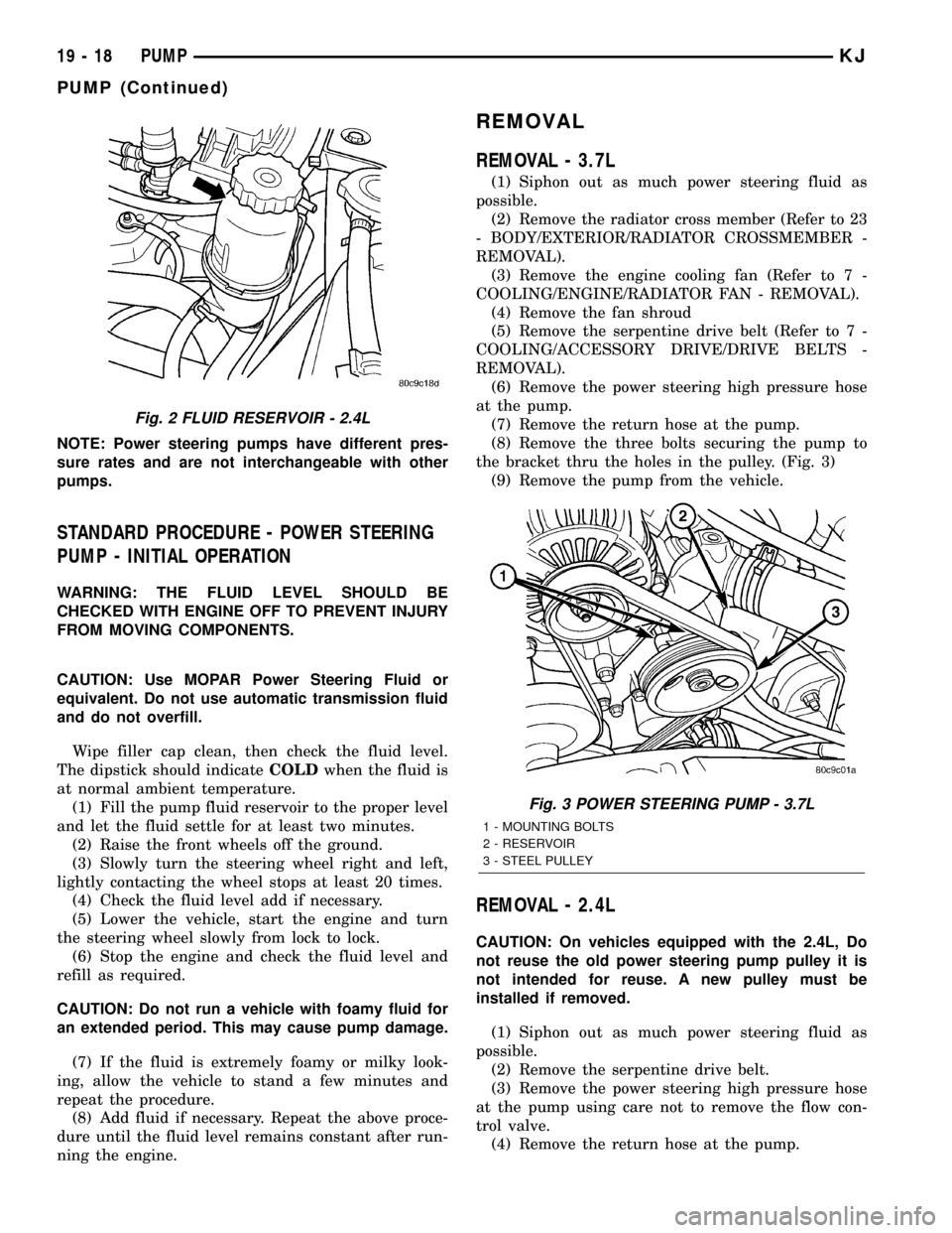
Fig. 2 FLUID RESERVOIR - 2.4L
Fig. 3 POWER STEERING PUMP - 3.7L
1 - MOUNTING BOLTS
2 - RESERVOIR
3 - STEEL PULLEY
19 - 18 PUMPKJ
PUMP (Continued)
Page 1462 of 1803
DIAGNOSIS AND TESTING - TREAD WEAR
INDICATORS
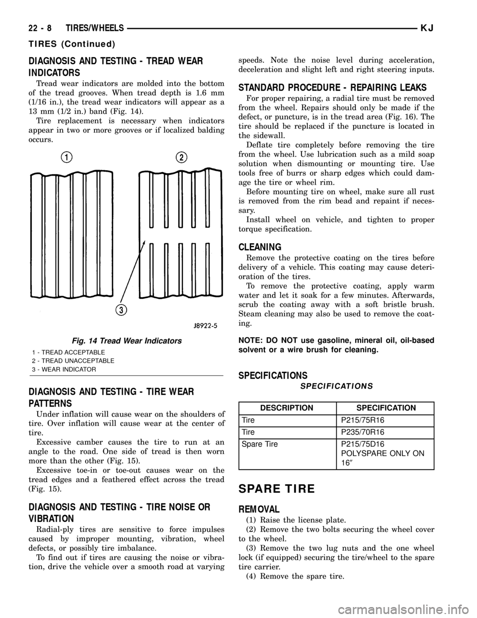
Tread wear indicators are molded into the bottom
of the tread grooves. When tread depth is 1.6 mm
(1/16 in.), the tread wear indicators will appear as a
13 mm (1/2 in.) band (Fig. 14).
Tire replacement is necessary when indicators
appear in two or more grooves or if localized balding
occurs.
DIAGNOSIS AND TESTING - TIRE WEAR
PATTERNS
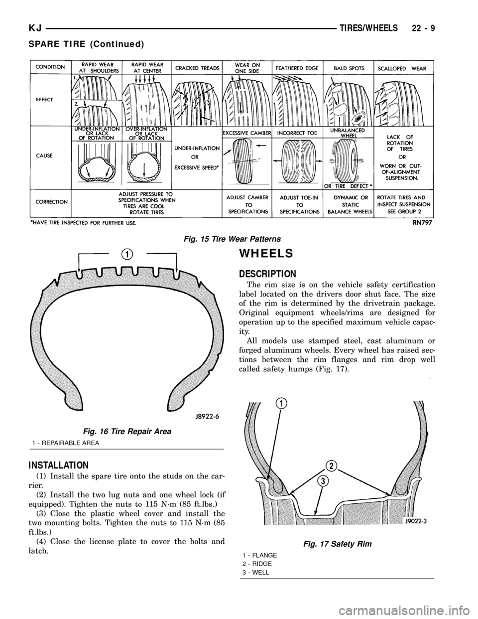
Under inflation will cause wear on the shoulders of
tire. Over inflation will cause wear at the center of
tire.
Excessive camber causes the tire to run at an
angle to the road. One side of tread is then worn
more than the other (Fig. 15).
Excessive toe-in or toe-out causes wear on the
tread edges and a feathered effect across the tread
(Fig. 15).
DIAGNOSIS AND TESTING - TIRE NOISE OR
VIBRATION
Radial-ply tires are sensitive to force impulses
caused by improper mounting, vibration, wheel
defects, or possibly tire imbalance.
To find out if tires are causing the noise or vibra-
tion, drive the vehicle over a smooth road at varyingspeeds. Note the noise level during acceleration,
deceleration and slight left and right steering inputs.
STANDARD PROCEDURE - REPAIRING LEAKS
For proper repairing, a radial tire must be removed
from the wheel. Repairs should only be made if the
defect, or puncture, is in the tread area (Fig. 16). The
tire should be replaced if the puncture is located in
the sidewall.
Deflate tire completely before removing the tire
from the wheel. Use lubrication such as a mild soap
solution when dismounting or mounting tire. Use
tools free of burrs or sharp edges which could dam-
age the tire or wheel rim.
Before mounting tire on wheel, make sure all rust
is removed from the rim bead and repaint if neces-
sary.
Install wheel on vehicle, and tighten to proper
torque specification.
CLEANING
Remove the protective coating on the tires before
delivery of a vehicle. This coating may cause deteri-
oration of the tires.
To remove the protective coating, apply warm
water and let it soak for a few minutes. Afterwards,
scrub the coating away with a soft bristle brush.
Steam cleaning may also be used to remove the coat-
ing.
NOTE: DO NOT use gasoline, mineral oil, oil-based
solvent or a wire brush for cleaning.
SPECIFICATIONS
SPECIFICATIONS
DESCRIPTION SPECIFICATION
Tire P215/75R16
Tire P235/70R16
Spare Tire P215/75D16
POLYSPARE ONLY ON
169
SPARE TIRE
REMOVAL
(1) Raise the license plate.
(2) Remove the two bolts securing the wheel cover
to the wheel.
(3) Remove the two lug nuts and the one wheel
lock (if equipped) securing the tire/wheel to the spare
tire carrier.
(4) Remove the spare tire.
Fig. 14 Tread Wear Indicators
1 - TREAD ACCEPTABLE
2 - TREAD UNACCEPTABLE
3 - WEAR INDICATOR
22 - 8 TIRES/WHEELSKJ
TIRES (Continued)
Page 1463 of 1803
INSTALLATION
(1) Install the spare tire onto the studs on the car-
rier.
(2) Install the two lug nuts and one wheel lock (if
equipped). Tighten the nuts to 115 N´m (85 ft.lbs.)
(3) Close the plastic wheel cover and install the
two mounting bolts. Tighten the nuts to 115 N´m (85
ft.lbs.)
(4) Close the license plate to cover the bolts and
latch.
WHEELS
DESCRIPTION
The rim size is on the vehicle safety certification
label located on the drivers door shut face. The size
of the rim is determined by the drivetrain package.
Original equipment wheels/rims are designed for
operation up to the specified maximum vehicle capac-
ity.
All models use stamped steel, cast aluminum or
forged aluminum wheels. Every wheel has raised sec-
tions between the rim flanges and rim drop well
called safety humps (Fig. 17).
Fig. 15 Tire Wear Patterns
Fig. 16 Tire Repair Area
1 - REPAIRABLE AREA
Fig. 17 Safety Rim
1 - FLANGE
2 - RIDGE
3 - WELL
KJTIRES/WHEELS 22 - 9
SPARE TIRE (Continued)
Page 1603 of 1803
(2) Remove the clip and remove the lock cylinder
switch.
(3) Remove the screw and remove the lock cylin-
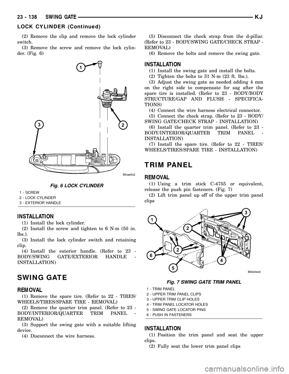
der. (Fig. 6)
INSTALLATION
(1) Install the lock cylinder.
(2) Install the screw and tighten to 6 N´m (50 in.
lbs.).
(3) Install the lock cylinder switch and retaining
clip.
(4) Install the exterior handle. (Refer to 23 -
BODY/SWING GATE/EXTERIOR HANDLE -
INSTALLATION)
SWING GATE
REMOVAL
(1) Remove the spare tire. (Refer to 22 - TIRES/
WHEELS/TIRES/SPARE TIRE - REMOVAL)
(2) Remove the quarter trim panel. (Refer to 23 -
BODY/INTERIOR/QUARTER TRIM PANEL -
REMOVAL)
(3) Support the swing gate with a suitable lifting
device.
(4) Disconnect the wire harness.(5) Disconnect the check strap from the d-pillar.
(Refer to 23 - BODY/SWING GATE/CHECK STRAP -
REMOVAL)
(6) Remove the bolts and remove the swing gate.
INSTALLATION
(1) Install the swing gate and install the bolts.
(2) Tighten the bolts to 31 N´m (23 ft. lbs.).
(3) Adjust the swing gate as needed adding 4 mm
on the right side to compensate for sag after the
spare tire is installed. (Refer to 23 - BODY/BODY
STRUCTURE/GAP AND FLUSH - SPECIFICA-
TIONS)
(4) Connect the wire harness electrical connector.
(5) Connect the check strap. (Refer to 23 - BODY/
SWING GATE/CHECK STRAP - INSTALLATION)
(6) Install the quarter trim panel. (Refer to 23 -
BODY/INTERIOR/QUARTER TRIM PANEL -
INSTALLATION)
(7) Install the spare tire. (Refer to 22 - TIRES/
WHEELS/TIRES/SPARE TIRE - INSTALLATION)
TRIM PANEL
REMOVAL
(1) Using a trim stick C-4755 or equivalent,
release the push pin fasteners. (Fig. 7)
(2) Lift trim panel up off of the upper trim panel
clips
INSTALLATION
(1) Position the trim panel and seat the upper
clips.
(2) Fully seat the lower trim panel clips
Fig. 6 LOCK CYLINDER
1 - SCREW
2 - LOCK CYLINDER
3 - EXTERIOR HANDLE
Fig. 7 SWING GATE TRIM PANEL
1 - TRIM PANEL
2 - UPPER TRIM PANEL CLIPS
3 - UPPER TRIM CLIP HOLES
4 - TRIM PANEL LOCATOR HOLES
5 - SWING GATE LOCATOR PINS
6 - PUSH IN FASTENERS
23 - 138 SWING GATEKJ
LOCK CYLINDER (Continued)
Page 1606 of 1803
(4) Clean adhesive residue from body with MOPAR
Super Clean solvent or equivalent.
INSTALLATION
(1) Remove protective cover from adhesive tape on
back of emblem.
(2) Position emblem properly on body.
(3) Press emblem firmly to body with palm of
hand.
(4) If temperature is below 21ÉC (70ÉF) warm
emblem with a heat lamp or gun to assure adhesion.
Do not exceed 52ÉC (120ÉF) when heating emblem.
FRONT FENDER
REMOVAL
(1) Remove the wheel opening splash shield. (Refer
to 23 - BODY/EXTERIOR/FRONT WHEELHOUSE
SPLASH SHIELD - REMOVAL)
(2) Remove the fascia assembly. (Refer to 13 -
FRAME & BUMPERS/BUMPERS/FRONT FASCIA -
REMOVAL)
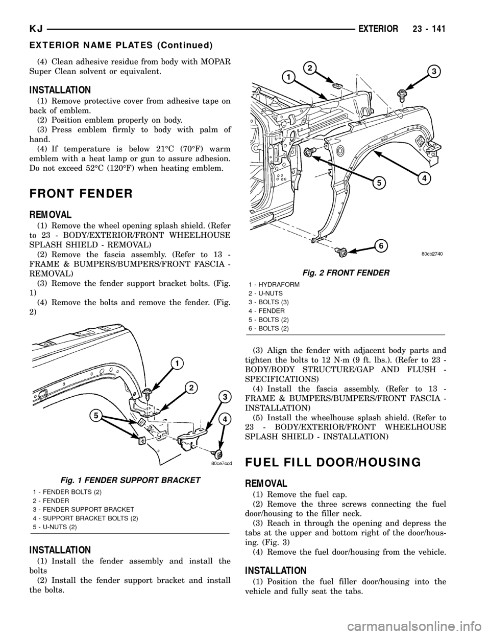
(3) Remove the fender support bracket bolts. (Fig.
1)
(4) Remove the bolts and remove the fender. (Fig.
2)
INSTALLATION
(1) Install the fender assembly and install the
bolts
(2) Install the fender support bracket and install
the bolts.(3) Align the fender with adjacent body parts and
tighten the bolts to 12 N´m (9 ft. lbs.). (Refer to 23 -
BODY/BODY STRUCTURE/GAP AND FLUSH -
SPECIFICATIONS)
(4) Install the fascia assembly. (Refer to 13 -
FRAME & BUMPERS/BUMPERS/FRONT FASCIA -
INSTALLATION)
(5) Install the wheelhouse splash shield. (Refer to
23 - BODY/EXTERIOR/FRONT WHEELHOUSE
SPLASH SHIELD - INSTALLATION)
FUEL FILL DOOR/HOUSING
REMOVAL
(1) Remove the fuel cap.
(2) Remove the three screws connecting the fuel
door/housing to the filler neck.
(3) Reach in through the opening and depress the
tabs at the upper and bottom right of the door/hous-
ing. (Fig. 3)
(4) Remove the fuel door/housing from the vehicle.
INSTALLATION
(1) Position the fuel filler door/housing into the
vehicle and fully seat the tabs.
Fig. 1 FENDER SUPPORT BRACKET
1 - FENDER BOLTS (2)
2 - FENDER
3 - FENDER SUPPORT BRACKET
4 - SUPPORT BRACKET BOLTS (2)
5 - U-NUTS (2)
Fig. 2 FRONT FENDER
1 - HYDRAFORM
2 - U-NUTS
3 - BOLTS (3)
4 - FENDER
5 - BOLTS (2)
6 - BOLTS (2)
KJEXTERIOR 23 - 141
EXTERIOR NAME PLATES (Continued)
Page 1608 of 1803
FRONT WHEELHOUSE
SPLASH SHIELD
REMOVAL
(1) Remove the wheel flare molding. (Refer to 23 -
BODY/EXTERIOR/FRONT WHEEL OPENING
FLARE MOLDING - REMOVAL)
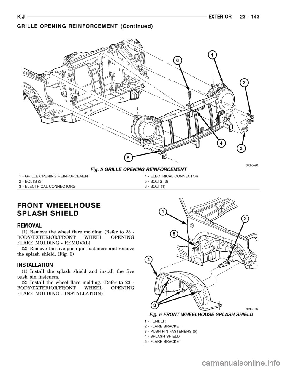
(2) Remove the five push pin fasteners and remove
the splash shield. (Fig. 6)
INSTALLATION
(1) Install the splash shield and install the five
push pin fasteners.
(2) Install the wheel flare molding. (Refer to 23 -
BODY/EXTERIOR/FRONT WHEEL OPENING
FLARE MOLDING - INSTALLATION)
Fig. 5 GRILLE OPENING REINFORCEMENT
1 - GRILLE OPENING REINFORCEMENT
2 - BOLTS (3)
3 - ELECTRICAL CONNECTORS4 - ELECTRICAL CONNECTOR
5 - BOLTS (3)
6 - BOLT (1)
Fig. 6 FRONT WHEELHOUSE SPLASH SHIELD
1 - FENDER
2 - FLARE BRACKET
3 - PUSH PIN FASTENERS (5)
4 - SPLASH SHIELD
5 - FLARE BRACKET
KJEXTERIOR 23 - 143
GRILLE OPENING REINFORCEMENT (Continued)
Page 1609 of 1803
LUGGAGE RACK
REMOVAL
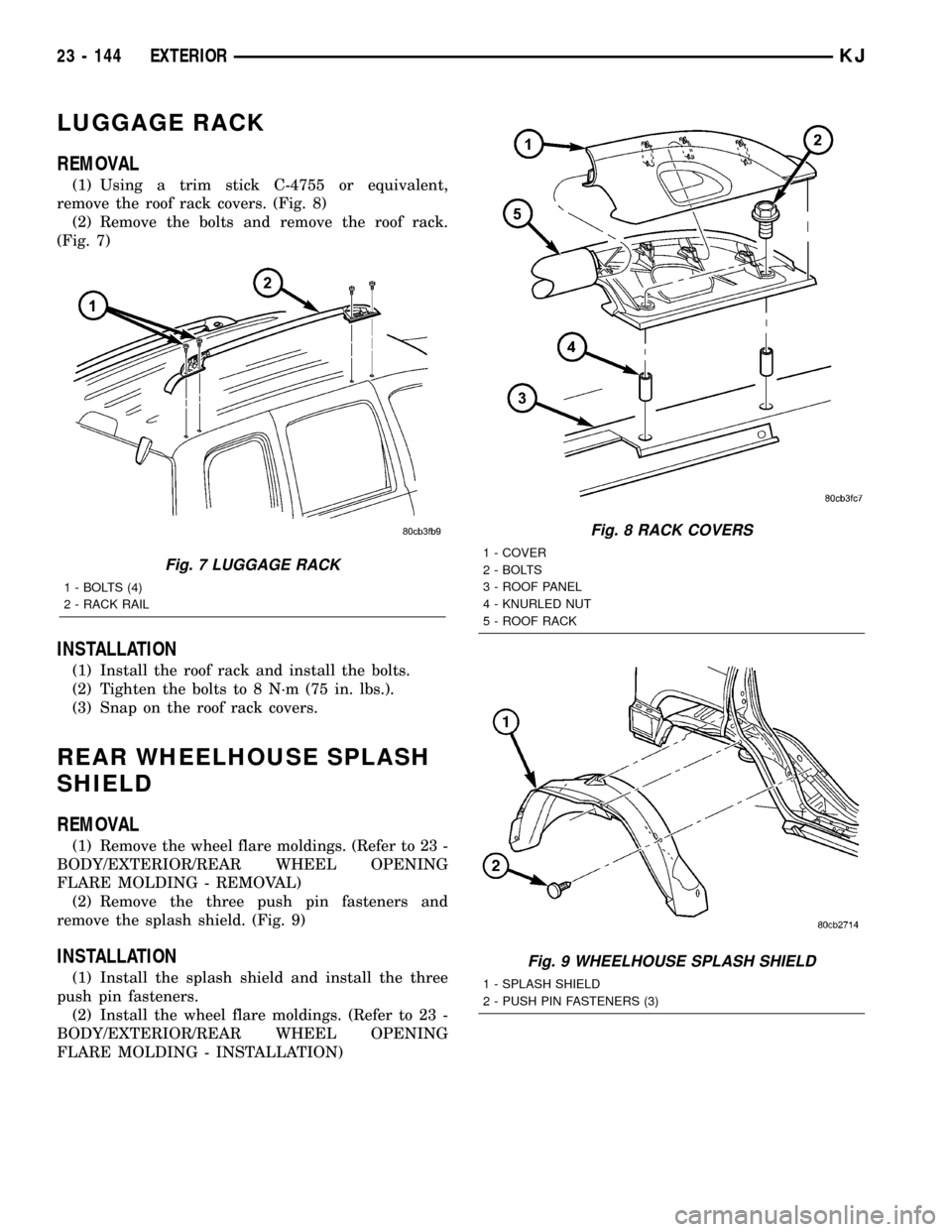
(1) Using a trim stick C-4755 or equivalent,
remove the roof rack covers. (Fig. 8)
(2) Remove the bolts and remove the roof rack.
(Fig. 7)
INSTALLATION
(1) Install the roof rack and install the bolts.
(2) Tighten the bolts to 8 N´m (75 in. lbs.).
(3) Snap on the roof rack covers.
REAR WHEELHOUSE SPLASH
SHIELD
REMOVAL
(1) Remove the wheel flare moldings. (Refer to 23 -
BODY/EXTERIOR/REAR WHEEL OPENING
FLARE MOLDING - REMOVAL)
(2) Remove the three push pin fasteners and
remove the splash shield. (Fig. 9)
INSTALLATION
(1) Install the splash shield and install the three
push pin fasteners.
(2) Install the wheel flare moldings. (Refer to 23 -
BODY/EXTERIOR/REAR WHEEL OPENING
FLARE MOLDING - INSTALLATION)
Fig. 7 LUGGAGE RACK
1 - BOLTS (4)
2 - RACK RAIL
Fig. 8 RACK COVERS
1 - COVER
2 - BOLTS
3 - ROOF PANEL
4 - KNURLED NUT
5 - ROOF RACK
Fig. 9 WHEELHOUSE SPLASH SHIELD
1 - SPLASH SHIELD
2 - PUSH PIN FASTENERS (3)
23 - 144 EXTERIORKJ
Page 1611 of 1803
(4) Position the door flare and seat the clips.
(5) Install five new rivets through the inside sur-
face of the door attaching the flare to the door.
RADIATOR CROSSMEMBER
REMOVAL
(1) Remove the grille. (Refer to 23 - BODY/EXTE-
RIOR/GRILLE - REMOVAL)
(2) Remove the hood latch. (Refer to 23 - BODY/
HOOD/LATCH - REMOVAL)(3) Remove the bolt securing the washer bottle to
the crossmember.
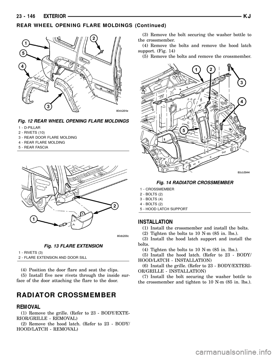
(4) Remove the bolts and remove the hood latch
support. (Fig. 14)
(5) Remove the bolts and remove the crossmember.
INSTALLATION
(1) Install the crossmember and install the bolts.
(2) Tighten the bolts to 10 N´m (85 in. lbs.).
(3) Install the hood latch support and install the
bolts.
(4) Tighten the bolts to 10 N´m (85 in. lbs.).
(5) Install the hood latch. (Refer to 23 - BODY/
HOOD/LATCH - INSTALLATION)
(6) Install the grille. (Refer to 23 - BODY/EXTERI-
OR/GRILLE - INSTALLATION)
(7) Install the bolt securing the washer bottle to
the crossmember and tighten to 10 N´m (85 in. lbs.).
Fig. 12 REAR WHEEL OPENING FLARE MOLDINGS
1 - D-PILLAR
2 - RIVETS (10)
3 - REAR DOOR FLARE MOLDING
4 - REAR FLARE MOLDING
5 - REAR FASCIA
Fig. 13 FLARE EXTENSION
1 - RIVETS (3)
2 - FLARE EXTENSION AND DOOR SILL
Fig. 14 RADIATOR CROSSMEMBER
1 - CROSSMEMBER
2 - BOLTS (2)
3 - BOLTS (4)
4 - BOLTS (2)
5 - HOOD LATCH SUPPORT
23 - 146 EXTERIORKJ
REAR WHEEL OPENING FLARE MOLDINGS (Continued)