2002 JEEP LIBERTY Engine
[x] Cancel search: EnginePage 1342 of 1803
REAR MOUNT
REMOVAL
NOTE: A resilient rubber cushion supports the
transmission at the rear between the transmission
extension housing and the rear support crossmem-
ber or skid plate.
(1) Disconnect negative cable from battery.
(2) Raise the vehicle and support the transmission.
(3) Remove the nuts holding the support cushion
to the crossmember. Remove the crossmember.
MANUAL TRANSMISSION
a. Remove the support cushion nuts and remove
the cushion.
b. Remove the transmission support bracket bolts
and remove the bracket from the transmission.
AUTOMATIC TRANSMISSION
c. Remove the support cushion bolts and remove
the cushion and the support bracket from the trans-
mission (4WD) or from the adaptor bracket (2WD).
d. On 2WD vehicles, remove the bolts holding the
transmission support adaptor bracket to the trans-
mission. Remove the adaptor bracket.
INSTALLATION
MANUAL TRANSMISSION:
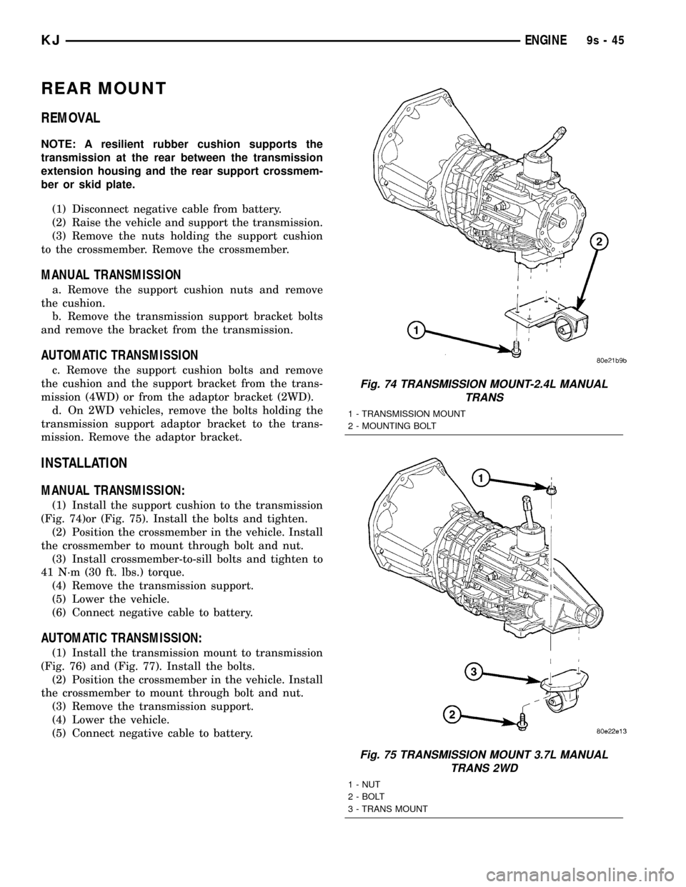
(1) Install the support cushion to the transmission
(Fig. 74)or (Fig. 75). Install the bolts and tighten.
(2) Position the crossmember in the vehicle. Install
the crossmember to mount through bolt and nut.
(3) Install crossmember-to-sill bolts and tighten to
41 N´m (30 ft. lbs.) torque.
(4) Remove the transmission support.
(5) Lower the vehicle.
(6) Connect negative cable to battery.
AUTOMATIC TRANSMISSION:
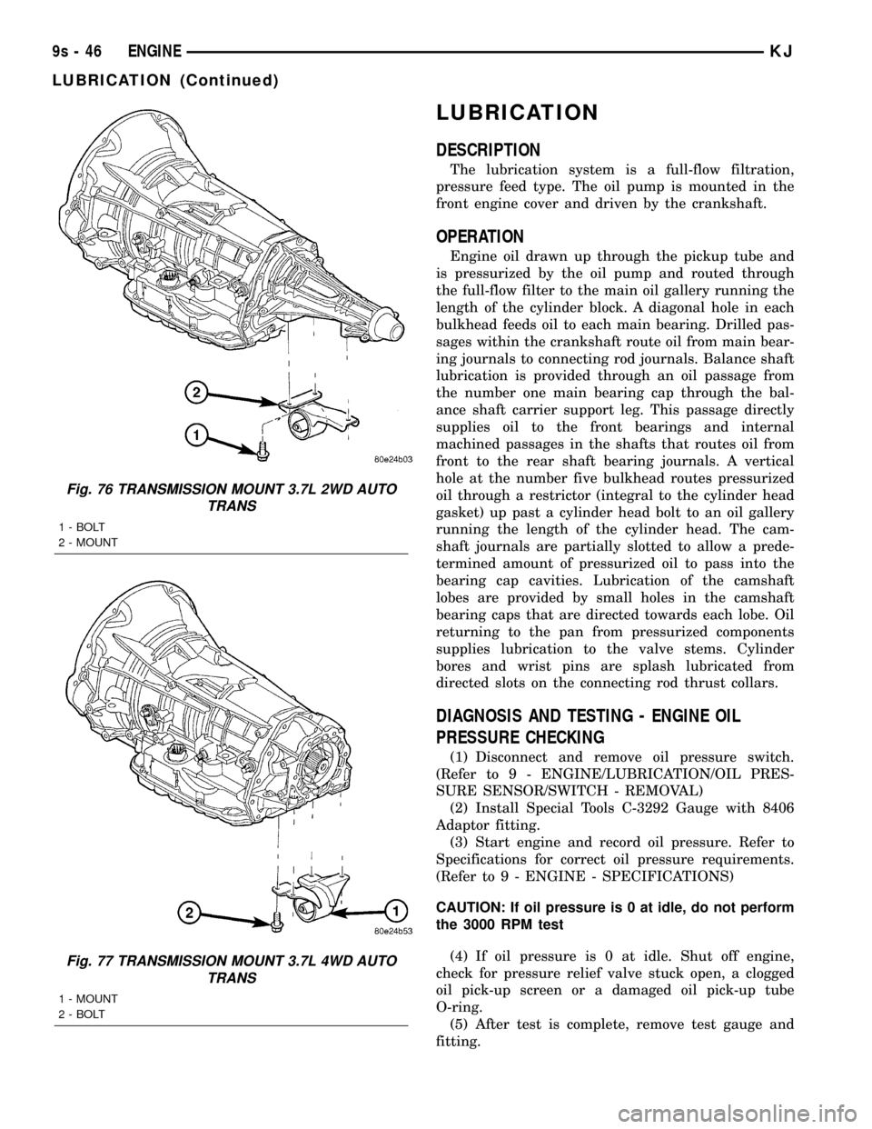
(1) Install the transmission mount to transmission
(Fig. 76) and (Fig. 77). Install the bolts.
(2) Position the crossmember in the vehicle. Install
the crossmember to mount through bolt and nut.
(3) Remove the transmission support.
(4) Lower the vehicle.
(5) Connect negative cable to battery.
Fig. 74 TRANSMISSION MOUNT-2.4L MANUAL
TRANS
1 - TRANSMISSION MOUNT
2 - MOUNTING BOLT
Fig. 75 TRANSMISSION MOUNT 3.7L MANUAL
TRANS 2WD
1 - NUT
2 - BOLT
3 - TRANS MOUNT
KJENGINE9s-45
Page 1343 of 1803
LUBRICATION
DESCRIPTION
The lubrication system is a full-flow filtration,
pressure feed type. The oil pump is mounted in the
front engine cover and driven by the crankshaft.
OPERATION
Engine oil drawn up through the pickup tube and
is pressurized by the oil pump and routed through
the full-flow filter to the main oil gallery running the
length of the cylinder block. A diagonal hole in each
bulkhead feeds oil to each main bearing. Drilled pas-
sages within the crankshaft route oil from main bear-
ing journals to connecting rod journals. Balance shaft
lubrication is provided through an oil passage from
the number one main bearing cap through the bal-
ance shaft carrier support leg. This passage directly
supplies oil to the front bearings and internal
machined passages in the shafts that routes oil from
front to the rear shaft bearing journals. A vertical
hole at the number five bulkhead routes pressurized
oil through a restrictor (integral to the cylinder head
gasket) up past a cylinder head bolt to an oil gallery
running the length of the cylinder head. The cam-
shaft journals are partially slotted to allow a prede-
termined amount of pressurized oil to pass into the
bearing cap cavities. Lubrication of the camshaft
lobes are provided by small holes in the camshaft
bearing caps that are directed towards each lobe. Oil
returning to the pan from pressurized components
supplies lubrication to the valve stems. Cylinder
bores and wrist pins are splash lubricated from
directed slots on the connecting rod thrust collars.
DIAGNOSIS AND TESTING - ENGINE OIL
PRESSURE CHECKING
(1) Disconnect and remove oil pressure switch.
(Refer to 9 - ENGINE/LUBRICATION/OIL PRES-
SURE SENSOR/SWITCH - REMOVAL)
(2) Install Special Tools C-3292 Gauge with 8406
Adaptor fitting.
(3) Start engine and record oil pressure. Refer to
Specifications for correct oil pressure requirements.
(Refer to 9 - ENGINE - SPECIFICATIONS)
CAUTION: If oil pressure is 0 at idle, do not perform
the 3000 RPM test
(4) If oil pressure is 0 at idle. Shut off engine,
check for pressure relief valve stuck open, a clogged
oil pick-up screen or a damaged oil pick-up tube
O-ring.
(5) After test is complete, remove test gauge and
fitting.
Fig. 76 TRANSMISSION MOUNT 3.7L 2WD AUTO
TRANS
1 - BOLT
2 - MOUNT
Fig. 77 TRANSMISSION MOUNT 3.7L 4WD AUTO
TRANS
1 - MOUNT
2 - BOLT
9s - 46 ENGINEKJ
LUBRICATION (Continued)
Page 1344 of 1803
(6) Install oil pressure switch and connector. (Refer
to 9 - ENGINE/LUBRICATION/OIL PRESSURE
SENSOR/SWITCH - INSTALLATION)
OIL
STANDARD PROCEDURE
ENGINE OIL LEVEL CHECK
The best time to check engine oil level is after it
has sat overnight, or if the engine has been running,
allow the engine to be shut off for at least 5 minutes
before checking oil level.
Checking the oil while the vehicle is on level
ground will improve the accuracy of the oil level
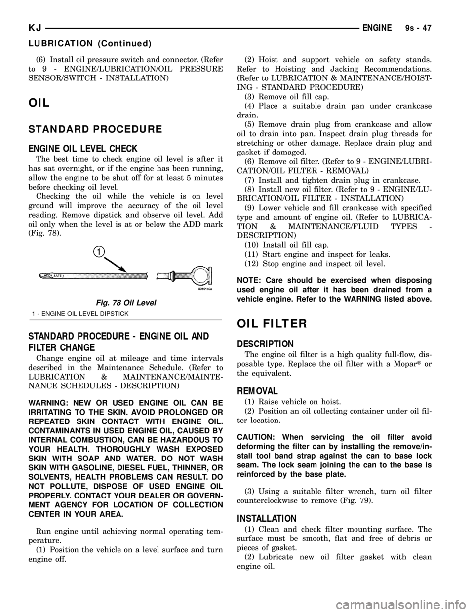
reading. Remove dipstick and observe oil level. Add
oil only when the level is at or below the ADD mark
(Fig. 78).
STANDARD PROCEDURE - ENGINE OIL AND
FILTER CHANGE
Change engine oil at mileage and time intervals
described in the Maintenance Schedule. (Refer to
LUBRICATION & MAINTENANCE/MAINTE-
NANCE SCHEDULES - DESCRIPTION)
WARNING: NEW OR USED ENGINE OIL CAN BE
IRRITATING TO THE SKIN. AVOID PROLONGED OR
REPEATED SKIN CONTACT WITH ENGINE OIL.
CONTAMINANTS IN USED ENGINE OIL, CAUSED BY
INTERNAL COMBUSTION, CAN BE HAZARDOUS TO
YOUR HEALTH. THOROUGHLY WASH EXPOSED
SKIN WITH SOAP AND WATER. DO NOT WASH
SKIN WITH GASOLINE, DIESEL FUEL, THINNER, OR
SOLVENTS, HEALTH PROBLEMS CAN RESULT. DO
NOT POLLUTE, DISPOSE OF USED ENGINE OIL
PROPERLY. CONTACT YOUR DEALER OR GOVERN-
MENT AGENCY FOR LOCATION OF COLLECTION
CENTER IN YOUR AREA.
Run engine until achieving normal operating tem-
perature.
(1) Position the vehicle on a level surface and turn
engine off.(2) Hoist and support vehicle on safety stands.
Refer to Hoisting and Jacking Recommendations.
(Refer to LUBRICATION & MAINTENANCE/HOIST-
ING - STANDARD PROCEDURE)
(3) Remove oil fill cap.
(4) Place a suitable drain pan under crankcase
drain.
(5) Remove drain plug from crankcase and allow
oil to drain into pan. Inspect drain plug threads for
stretching or other damage. Replace drain plug and
gasket if damaged.
(6) Remove oil filter. (Refer to 9 - ENGINE/LUBRI-
CATION/OIL FILTER - REMOVAL)
(7) Install and tighten drain plug in crankcase.
(8) Install new oil filter. (Refer to 9 - ENGINE/LU-
BRICATION/OIL FILTER - INSTALLATION)
(9) Lower vehicle and fill crankcase with specified
type and amount of engine oil. (Refer to LUBRICA-
TION & MAINTENANCE/FLUID TYPES -
DESCRIPTION)
(10) Install oil fill cap.
(11) Start engine and inspect for leaks.
(12) Stop engine and inspect oil level.
NOTE: Care should be exercised when disposing
used engine oil after it has been drained from a
vehicle engine. Refer to the WARNING listed above.
OIL FILTER
DESCRIPTION
The engine oil filter is a high quality full-flow, dis-
posable type. Replace the oil filter with a Mopartor
the equivalent.
REMOVAL
(1) Raise vehicle on hoist.
(2) Position an oil collecting container under oil fil-
ter location.
CAUTION: When servicing the oil filter avoid
deforming the filter can by installing the remove/in-
stall tool band strap against the can to base lock
seam. The lock seam joining the can to the base is
reinforced by the base plate.
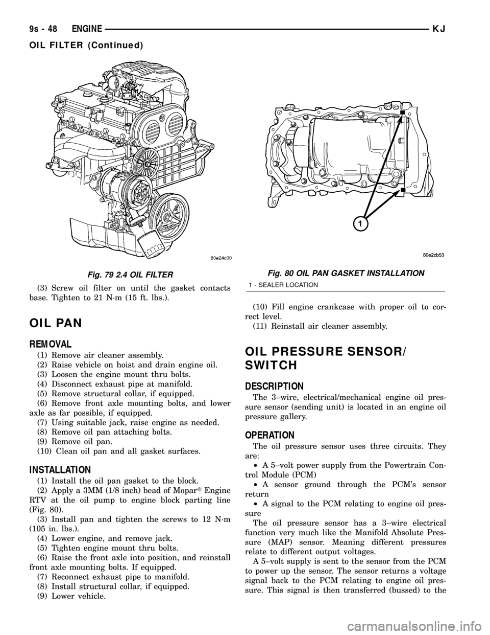
(3) Using a suitable filter wrench, turn oil filter
counterclockwise to remove (Fig. 79).
INSTALLATION
(1) Clean and check filter mounting surface. The
surface must be smooth, flat and free of debris or
pieces of gasket.
(2) Lubricate new oil filter gasket with clean
engine oil.
Fig. 78 Oil Level
1 - ENGINE OIL LEVEL DIPSTICK
KJENGINE9s-47
LUBRICATION (Continued)
Page 1345 of 1803
(3) Screw oil filter on until the gasket contacts
base. Tighten to 21 N´m (15 ft. lbs.).
OIL PAN
REMOVAL
(1) Remove air cleaner assembly.
(2) Raise vehicle on hoist and drain engine oil.
(3) Loosen the engine mount thru bolts.
(4) Disconnect exhaust pipe at manifold.
(5) Remove structural collar, if equipped.
(6) Remove front axle mounting bolts, and lower
axle as far possible, if equipped.
(7) Using suitable jack, raise engine as needed.
(8) Remove oil pan attaching bolts.
(9) Remove oil pan.
(10) Clean oil pan and all gasket surfaces.
INSTALLATION
(1) Install the oil pan gasket to the block.
(2) Apply a 3MM (1/8 inch) bead of MopartEngine
RTV at the oil pump to engine block parting line
(Fig. 80).
(3) Install pan and tighten the screws to 12 N´m
(105 in. lbs.).
(4) Lower engine, and remove jack.
(5) Tighten engine mount thru bolts.
(6) Raise the front axle into position, and reinstall
front axle mounting bolts. If equipped.
(7) Reconnect exhaust pipe to manifold.
(8) Install structural collar, if equipped.
(9) Lower vehicle.(10) Fill engine crankcase with proper oil to cor-
rect level.
(11) Reinstall air cleaner assembly.
OIL PRESSURE SENSOR/
SWITCH
DESCRIPTION
The 3±wire, electrical/mechanical engine oil pres-
sure sensor (sending unit) is located in an engine oil
pressure gallery.
OPERATION
The oil pressure sensor uses three circuits. They
are:
²A 5±volt power supply from the Powertrain Con-
trol Module (PCM)
²A sensor ground through the PCM's sensor
return
²A signal to the PCM relating to engine oil pres-
sure
The oil pressure sensor has a 3±wire electrical
function very much like the Manifold Absolute Pres-
sure (MAP) sensor. Meaning different pressures
relate to different output voltages.
A 5±volt supply is sent to the sensor from the PCM
to power up the sensor. The sensor returns a voltage
signal back to the PCM relating to engine oil pres-
sure. This signal is then transferred (bussed) to the
Fig. 79 2.4 OIL FILTERFig. 80 OIL PAN GASKET INSTALLATION
1 - SEALER LOCATION
9s - 48 ENGINEKJ
OIL FILTER (Continued)
Page 1346 of 1803
instrument panel on either a CCD or PCI bus circuit
(depending on vehicle line) to operate the oil pressure
gauge and the check gauges lamp. Ground for the
sensor is provided by the PCM through a low-noise
sensor return.
OIL PUMP
REMOVAL
(1) Disconnect negative cable from battery.
(2) Remove timing belt. (Refer to 9 - ENGINE/
VALVE TIMING/TIMING BELT/CHAIN AND
SPROCKETS - REMOVAL)
(3) Remove timing belt rear cover. (Refer to 9 -
ENGINE/VALVE TIMING/TIMING BELT / CHAIN
COVER(S) - REMOVAL)
(4) Remove oil pan. (Refer to 9 - ENGINE/LUBRI-
CATION/OIL PAN - REMOVAL)
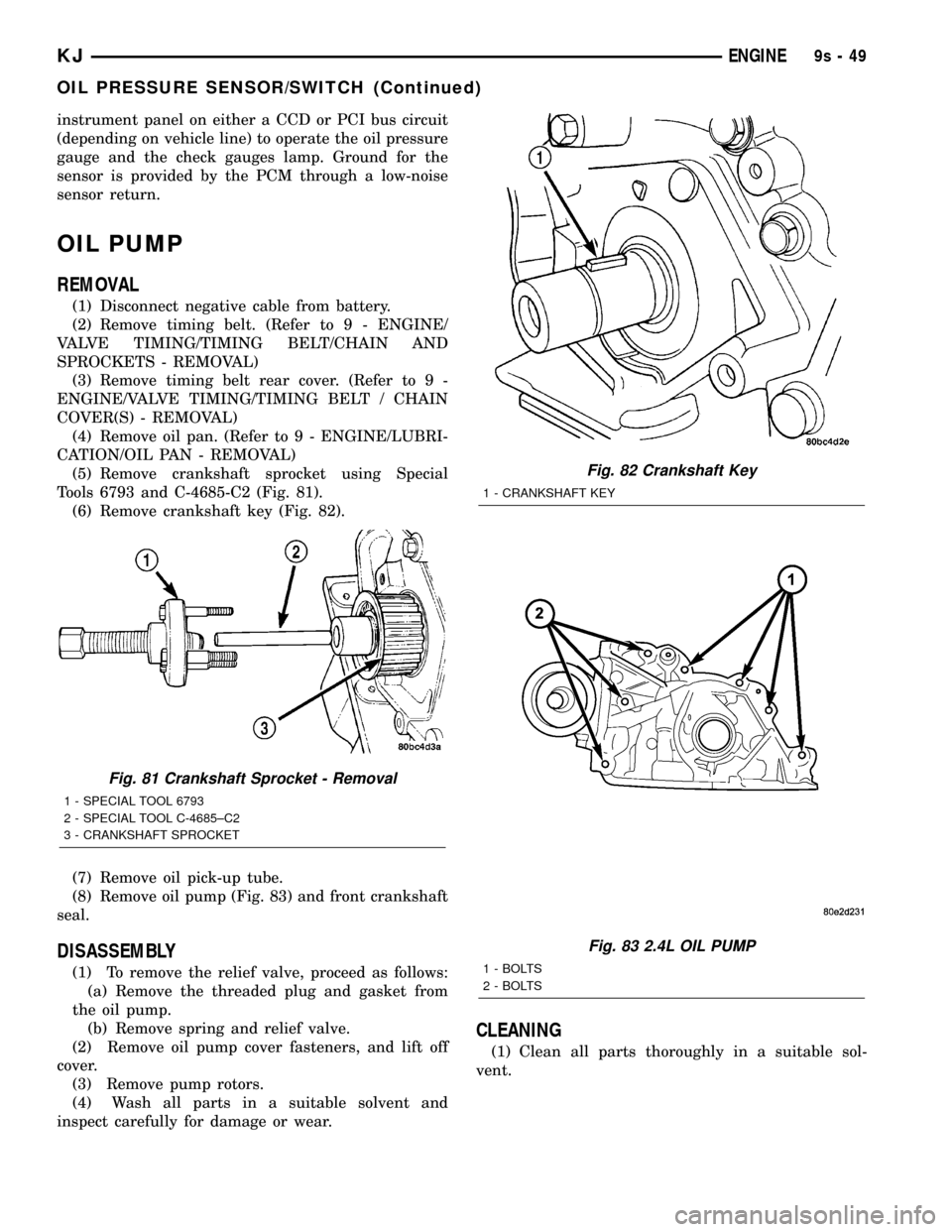
(5) Remove crankshaft sprocket using Special
Tools 6793 and C-4685-C2 (Fig. 81).
(6) Remove crankshaft key (Fig. 82).
(7) Remove oil pick-up tube.
(8) Remove oil pump (Fig. 83) and front crankshaft
seal.
DISASSEMBLY
(1) To remove the relief valve, proceed as follows:
(a) Remove the threaded plug and gasket from
the oil pump.
(b) Remove spring and relief valve.
(2) Remove oil pump cover fasteners, and lift off
cover.
(3) Remove pump rotors.
(4) Wash all parts in a suitable solvent and
inspect carefully for damage or wear.
CLEANING
(1) Clean all parts thoroughly in a suitable sol-
vent.
Fig. 81 Crankshaft Sprocket - Removal
1 - SPECIAL TOOL 6793
2 - SPECIAL TOOL C-4685±C2
3 - CRANKSHAFT SPROCKET
Fig. 82 Crankshaft Key
1 - CRANKSHAFT KEY
Fig. 83 2.4L OIL PUMP
1 - BOLTS
2 - BOLTS
KJENGINE9s-49
OIL PRESSURE SENSOR/SWITCH (Continued)
Page 1347 of 1803
INSPECTION
(1) Inspect the mating surface of the oil pump.
Surface should be smooth. Replace pump cover if
scratched or grooved.
(2) Lay a straightedge across the pump cover sur-
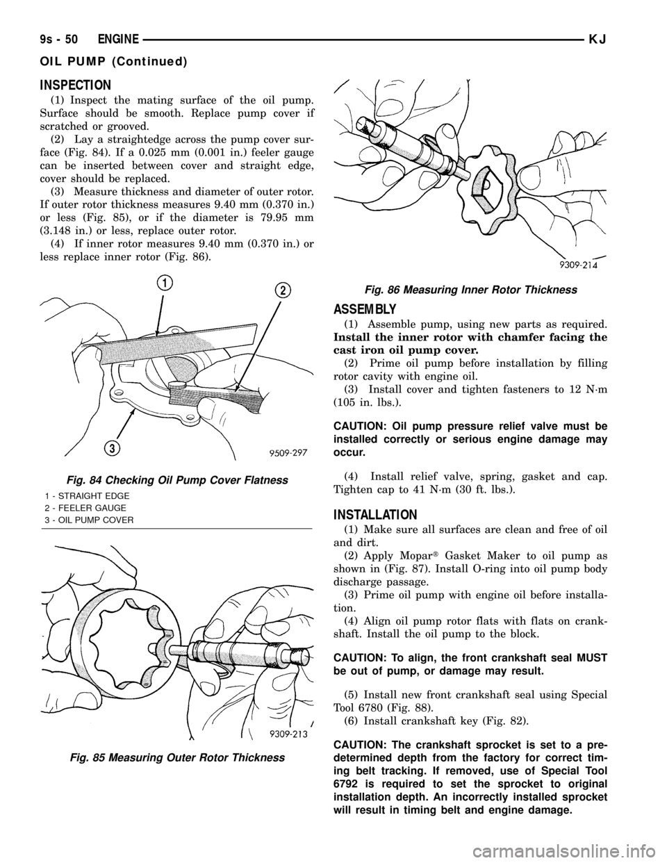
face (Fig. 84). If a 0.025 mm (0.001 in.) feeler gauge
can be inserted between cover and straight edge,
cover should be replaced.
(3) Measure thickness and diameter of outer rotor.
If outer rotor thickness measures 9.40 mm (0.370 in.)
or less (Fig. 85), or if the diameter is 79.95 mm
(3.148 in.) or less, replace outer rotor.
(4) If inner rotor measures 9.40 mm (0.370 in.) or
less replace inner rotor (Fig. 86).
ASSEMBLY
(1) Assemble pump, using new parts as required.
Install the inner rotor with chamfer facing the
cast iron oil pump cover.
(2) Prime oil pump before installation by filling
rotor cavity with engine oil.
(3) Install cover and tighten fasteners to 12 N´m
(105 in. lbs.).
CAUTION: Oil pump pressure relief valve must be
installed correctly or serious engine damage may
occur.
(4) Install relief valve, spring, gasket and cap.
Tighten cap to 41 N´m (30 ft. lbs.).
INSTALLATION
(1) Make sure all surfaces are clean and free of oil
and dirt.
(2) Apply MopartGasket Maker to oil pump as
shown in (Fig. 87). Install O-ring into oil pump body
discharge passage.
(3) Prime oil pump with engine oil before installa-
tion.
(4) Align oil pump rotor flats with flats on crank-
shaft. Install the oil pump to the block.
CAUTION: To align, the front crankshaft seal MUST
be out of pump, or damage may result.
(5) Install new front crankshaft seal using Special
Tool 6780 (Fig. 88).
(6) Install crankshaft key (Fig. 82).
CAUTION: The crankshaft sprocket is set to a pre-
determined depth from the factory for correct tim-
ing belt tracking. If removed, use of Special Tool
6792 is required to set the sprocket to original
installation depth. An incorrectly installed sprocket
will result in timing belt and engine damage.
Fig. 84 Checking Oil Pump Cover Flatness
1 - STRAIGHT EDGE
2 - FEELER GAUGE
3 - OIL PUMP COVER
Fig. 85 Measuring Outer Rotor Thickness
Fig. 86 Measuring Inner Rotor Thickness
9s - 50 ENGINEKJ
OIL PUMP (Continued)
Page 1348 of 1803
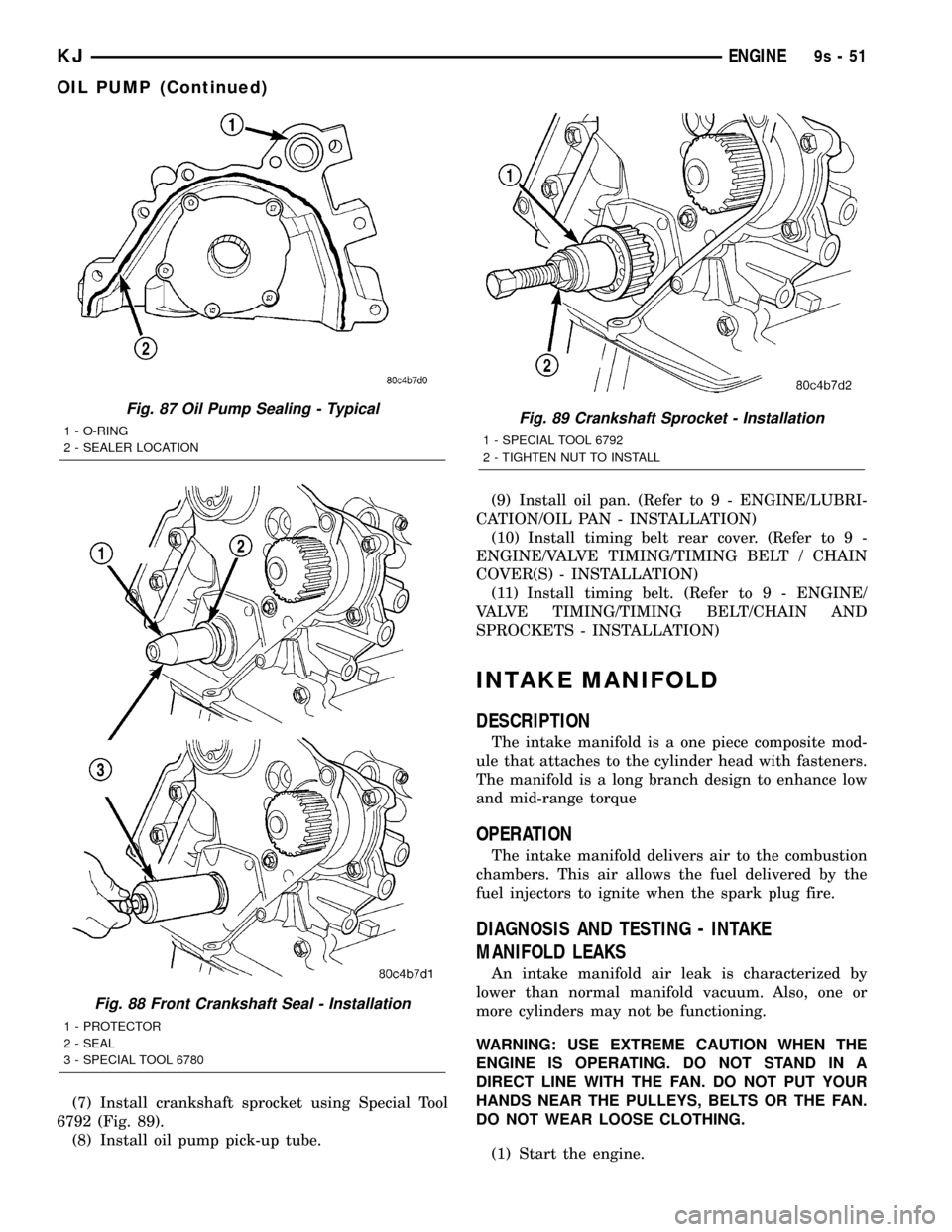
(7) Install crankshaft sprocket using Special Tool
6792 (Fig. 89).
(8) Install oil pump pick-up tube.(9) Install oil pan. (Refer to 9 - ENGINE/LUBRI-
CATION/OIL PAN - INSTALLATION)
(10) Install timing belt rear cover. (Refer to 9 -
ENGINE/VALVE TIMING/TIMING BELT / CHAIN
COVER(S) - INSTALLATION)
(11) Install timing belt. (Refer to 9 - ENGINE/
VALVE TIMING/TIMING BELT/CHAIN AND
SPROCKETS - INSTALLATION)
INTAKE MANIFOLD
DESCRIPTION
The intake manifold is a one piece composite mod-
ule that attaches to the cylinder head with fasteners.
The manifold is a long branch design to enhance low
and mid-range torque
OPERATION
The intake manifold delivers air to the combustion
chambers. This air allows the fuel delivered by the
fuel injectors to ignite when the spark plug fire.
DIAGNOSIS AND TESTING - INTAKE
MANIFOLD LEAKS
An intake manifold air leak is characterized by
lower than normal manifold vacuum. Also, one or
more cylinders may not be functioning.
WARNING: USE EXTREME CAUTION WHEN THE
ENGINE IS OPERATING. DO NOT STAND IN A
DIRECT LINE WITH THE FAN. DO NOT PUT YOUR
HANDS NEAR THE PULLEYS, BELTS OR THE FAN.
DO NOT WEAR LOOSE CLOTHING.
(1) Start the engine.
Fig. 87 Oil Pump Sealing - Typical
1 - O-RING
2 - SEALER LOCATION
Fig. 88 Front Crankshaft Seal - Installation
1 - PROTECTOR
2 - SEAL
3 - SPECIAL TOOL 6780
Fig. 89 Crankshaft Sprocket - Installation
1 - SPECIAL TOOL 6792
2 - TIGHTEN NUT TO INSTALL
KJENGINE9s-51
OIL PUMP (Continued)
Page 1349 of 1803
(2) Spray a small stream of water (Spray Bottle) at
the suspected leak area.
(3) If engine RPM'S change, the area of the sus-
pected leak has been found.
(4) Repair as required.
REMOVAL
(1) Disconnect negative cable from battery.
(2) Disconnect connector from inlet air tempera-
ture sensor.
(3) Disconnect air intake tube at throttle body and
remove upper air cleaner housing.
(4) Disconnect connector from throttle position
sensor (TPS).
(5) Disconnect connector from idle air control (IAC)
motor.
(6) Disconnect connector from MAP sensor.
(7) Remove vacuum lines for purge solenoid and
PCV valve at intake manifold.
(8) Remove vacuum lines for power brake booster,
LDP, EGR transducer, and speed control vacuum res-
ervoir (if equipped) at intake manifold fittings.
(9) Disconnect throttle, speed control (if equipped),
and transaxle control (if equipped) and cables from
throttle lever and bracket. (Refer to 14 - FUEL SYS-
TEM/FUEL INJECTION/THROTTLE CONTROL
CABLE - REMOVAL)
(10) Perform fuel system pressure release proce-
durebefore attempting any repairs.(Refer to 14 -
FUEL SYSTEM/FUEL DELIVERY - STANDARD
PROCEDURE)
(11) Disconnect fuel line. (Refer to 14 - FUEL SYS-
TEM/FUEL DELIVERY/QUICK CONNECT FIT-
TING - STANDARD PROCEDURE)
(12) Disconnect coolant temperature sensor/fuel
injector wire harness connector.
(13) Disconnect fuel injector harness.
(14) Remove intake manifold to cylinder head fas-
teners.
(15) Remove the manifold from engine.
CAUTION: Cover intake manifold openings to pre-
vent foreign material from entering engine.
(16) Inspect the manifold. (Refer to 9 - ENGINE/
MANIFOLDS/INTAKE MANIFOLD - INSPECTION)
INSPECTION
(1) Check manifold surfaces for flatness with
straight edge. Surface must be flat within 0.15 mm
per 300 mm (0.006 in. per foot) of manifold length.
(2) Inspect manifold for cracks or distortion.
Replace manifold if necessary.
INSTALLATION
(1) Clean manifold sealing surfaces.
(2) Install new manifold to cylinder head seals.
(3) Install manifold to head.
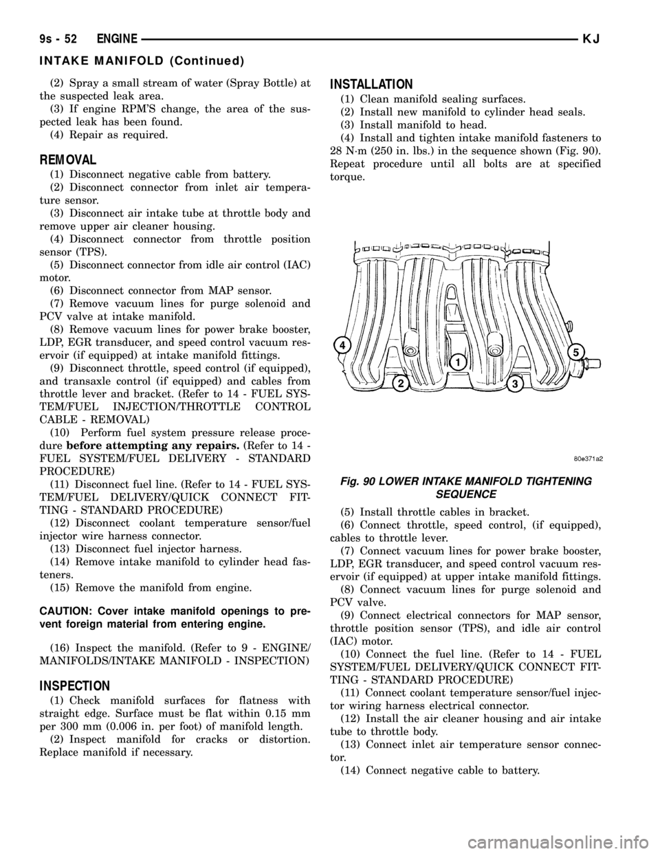
(4) Install and tighten intake manifold fasteners to
28 N´m (250 in. lbs.) in the sequence shown (Fig. 90).
Repeat procedure until all bolts are at specified
torque.
(5) Install throttle cables in bracket.
(6) Connect throttle, speed control, (if equipped),
cables to throttle lever.
(7) Connect vacuum lines for power brake booster,
LDP, EGR transducer, and speed control vacuum res-
ervoir (if equipped) at upper intake manifold fittings.
(8) Connect vacuum lines for purge solenoid and
PCV valve.
(9) Connect electrical connectors for MAP sensor,
throttle position sensor (TPS), and idle air control
(IAC) motor.
(10) Connect the fuel line. (Refer to 14 - FUEL
SYSTEM/FUEL DELIVERY/QUICK CONNECT FIT-
TING - STANDARD PROCEDURE)
(11) Connect coolant temperature sensor/fuel injec-
tor wiring harness electrical connector.
(12) Install the air cleaner housing and air intake
tube to throttle body.
(13) Connect inlet air temperature sensor connec-
tor.
(14) Connect negative cable to battery.
Fig. 90 LOWER INTAKE MANIFOLD TIGHTENING
SEQUENCE
9s - 52 ENGINEKJ
INTAKE MANIFOLD (Continued)