2002 JEEP LIBERTY Engine
[x] Cancel search: EnginePage 1358 of 1803
INSTALLATION
BALANCE SHAFT TIMING
BALANCE SHAFT INSTALLATION
Balance shaft and carrier assembly installation is
the reverse of the removal procedure.During instal-
lation crankshaft-to-balance shaft timing must
be established. Refer to Timing procedure in
this section.
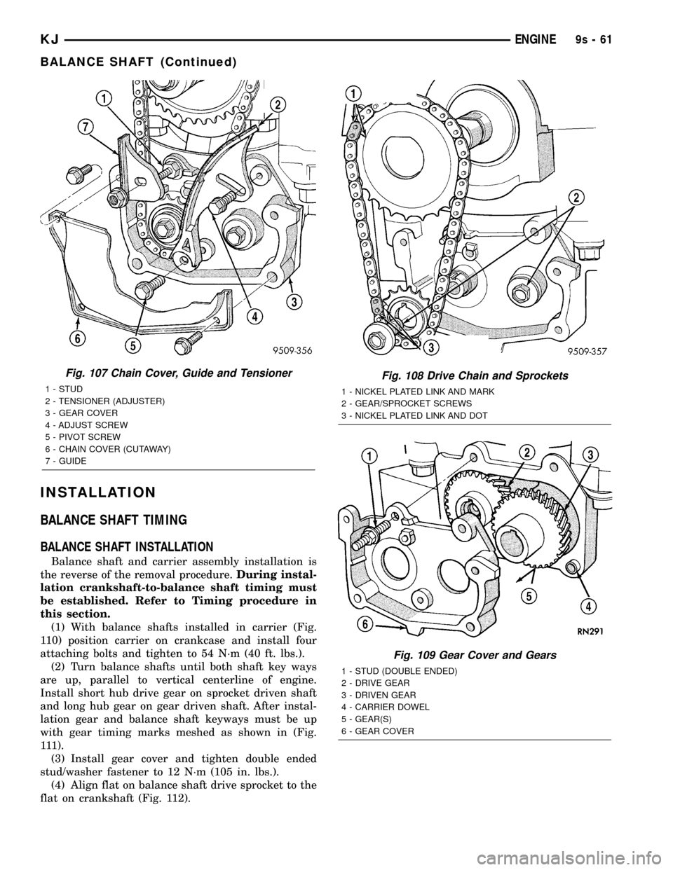
(1) With balance shafts installed in carrier (Fig.
110) position carrier on crankcase and install four
attaching bolts and tighten to 54 N´m (40 ft. lbs.).
(2) Turn balance shafts until both shaft key ways
are up, parallel to vertical centerline of engine.
Install short hub drive gear on sprocket driven shaft
and long hub gear on gear driven shaft. After instal-
lation gear and balance shaft keyways must be up
with gear timing marks meshed as shown in (Fig.
111).
(3) Install gear cover and tighten double ended
stud/washer fastener to 12 N´m (105 in. lbs.).
(4) Align flat on balance shaft drive sprocket to the
flat on crankshaft (Fig. 112).
Fig. 107 Chain Cover, Guide and Tensioner
1 - STUD
2 - TENSIONER (ADJUSTER)
3 - GEAR COVER
4 - ADJUST SCREW
5 - PIVOT SCREW
6 - CHAIN COVER (CUTAWAY)
7 - GUIDE
Fig. 108 Drive Chain and Sprockets
1 - NICKEL PLATED LINK AND MARK
2 - GEAR/SPROCKET SCREWS
3 - NICKEL PLATED LINK AND DOT
Fig. 109 Gear Cover and Gears
1 - STUD (DOUBLE ENDED)
2 - DRIVE GEAR
3 - DRIVEN GEAR
4 - CARRIER DOWEL
5 - GEAR(S)
6 - GEAR COVER
KJENGINE9s-61
BALANCE SHAFT (Continued)
Page 1359 of 1803
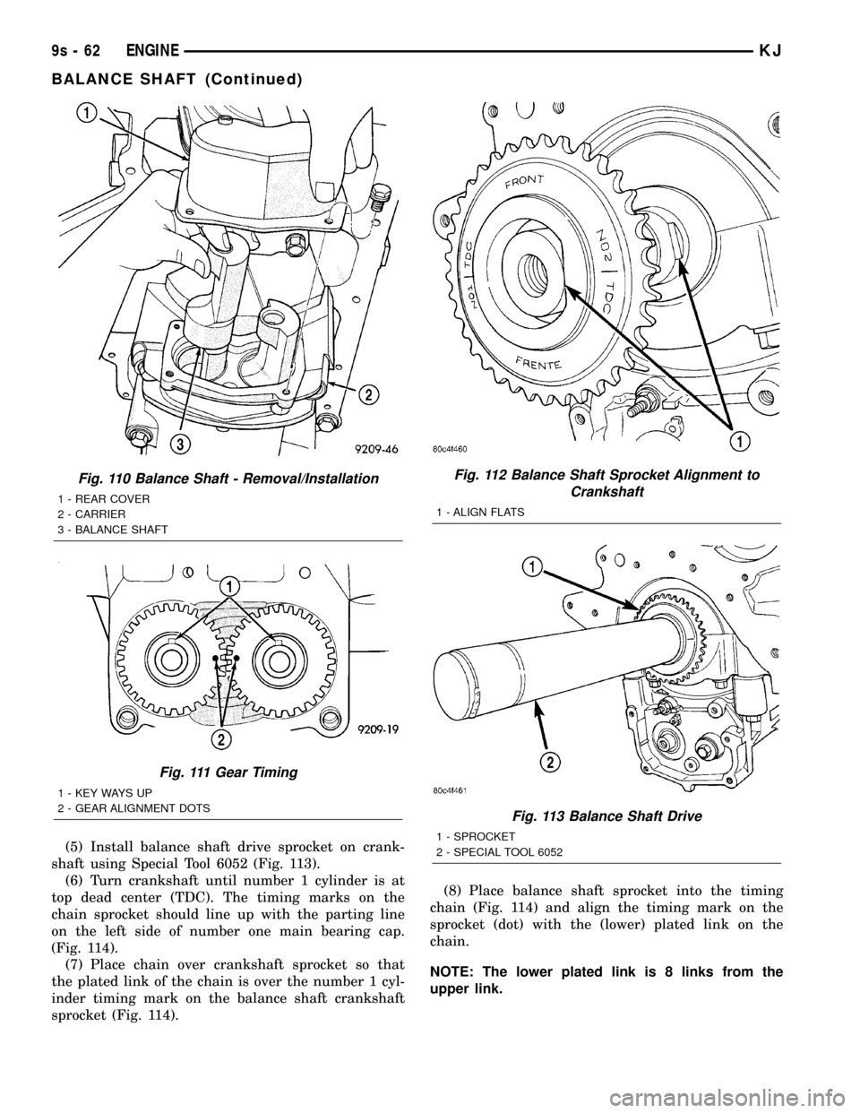
(5) Install balance shaft drive sprocket on crank-
shaft using Special Tool 6052 (Fig. 113).
(6) Turn crankshaft until number 1 cylinder is at
top dead center (TDC). The timing marks on the
chain sprocket should line up with the parting line
on the left side of number one main bearing cap.
(Fig. 114).
(7) Place chain over crankshaft sprocket so that
the plated link of the chain is over the number 1 cyl-
inder timing mark on the balance shaft crankshaft
sprocket (Fig. 114).(8) Place balance shaft sprocket into the timing
chain (Fig. 114) and align the timing mark on the
sprocket (dot) with the (lower) plated link on the
chain.
NOTE: The lower plated link is 8 links from the
upper link.
Fig. 110 Balance Shaft - Removal/Installation
1 - REAR COVER
2 - CARRIER
3 - BALANCE SHAFT
Fig. 111 Gear Timing
1 - KEY WAYS UP
2 - GEAR ALIGNMENT DOTS
Fig. 112 Balance Shaft Sprocket Alignment to
Crankshaft
1 - ALIGN FLATS
Fig. 113 Balance Shaft Drive
1 - SPROCKET
2 - SPECIAL TOOL 6052
9s - 62 ENGINEKJ
BALANCE SHAFT (Continued)
Page 1360 of 1803
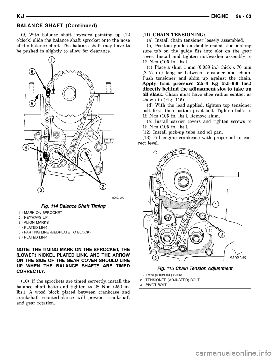
(9) With balance shaft keyways pointing up (12
o'clock) slide the balance shaft sprocket onto the nose
of the balance shaft. The balance shaft may have to
be pushed in slightly to allow for clearance.
NOTE: THE TIMING MARK ON THE SPROCKET, THE
(LOWER) NICKEL PLATED LINK, AND THE ARROW
ON THE SIDE OF THE GEAR COVER SHOULD LINE
UP WHEN THE BALANCE SHAFTS ARE TIMED
CORRECTLY.
(10) If the sprockets are timed correctly, install the
balance shaft bolts and tighten to 28 N´m (250 in.
lbs.). A wood block placed between crankcase and
crankshaft counterbalance will prevent crankshaft
and gear rotation.(11)CHAIN TENSIONING:
(a) Install chain tensioner loosely assembled.
(b) Position guide on double ended stud making
sure tab on the guide fits into slot on the gear
cover. Install and tighten nut/washer assembly to
12 N´m (105 in. lbs.).
(c) Place a shim 1 mm (0.039 in.) thick x 70 mm
(2.75 in.) long or between tensioner and chain.
Push tensioner and shim up against the chain.
Apply firm pressure 2.5±3 Kg (5.5±6.6 lbs.)
directly behind the adjustment slot to take up
all slack.Chain must have shoe radius contact as
shown in (Fig. 115).
(d) With the load applied, tighten top tensioner
bolt first, then bottom pivot bolt. Tighten bolts to
12 N´m (105 in. lbs.). Remove shim.
(e) Install carrier covers and tighten screws to
12 N´m (105 in. lbs.).
(12) Install pick-up tube and oil pan.
(13) Fill engine crankcase with proper oil to cor-
rect level.
Fig. 114 Balance Shaft Timing
1 - MARK ON SPROCKET
2 - KEYWAYS UP
3 - ALIGN MARKS
4 - PLATED LINK
5 - PARTING LINE (BEDPLATE TO BLOCK)
6 - PLATED LINK
Fig. 115 Chain Tension Adjustment
1 - 1MM (0.039 IN.) SHIM
2 - TENSIONER (ADJUSTER) BOLT
3 - PIVOT BOLT
KJENGINE9s-63
BALANCE SHAFT (Continued)
Page 1361 of 1803

BALANCE SHAFT CARRIER
REMOVAL
(Refer to 9 - ENGINE/VALVE TIMING/BALANCE
SHAFT - REMOVAL)
INSTALLATION
(Refer to 9 - ENGINE/VALVE TIMING/BALANCE
SHAFT - INSTALLATION)
BALANCE SHAFT CHAIN
REMOVAL
(Refer to 9 - ENGINE/VALVE TIMING/BALANCE
SHAFT - REMOVAL)
INSTALLATION
(Refer to 9 - ENGINE/VALVE TIMING/BALANCE
SHAFT - INSTALLATION)
9s - 64 ENGINEKJ
Page 1362 of 1803
EXHAUST SYSTEM
TABLE OF CONTENTS
page page
EXHAUST SYSTEM
DESCRIPTION..........................1
DIAGNOSIS AND TESTING - EXHAUST
SYSTEM.............................2
CATALYTIC CONVERTER
DESCRIPTION - CATALYTIC CONVERTER.....2
REMOVAL.............................2
INSPECTION...........................3
INSTALLATION..........................3CROSS-OVER PIPE
REMOVAL.............................3
INSTALLATION..........................3
HEAT SHIELDS
DESCRIPTION..........................4
MUFFLER
DESCRIPTION..........................4
REMOVAL.............................5
INSTALLATION..........................5
EXHAUST SYSTEM
DESCRIPTION
The basic exhaust system consists of an engine
exhaust manifold, exhaust down pipe, exhaust pipe,
exhaust heat shield(s), muffler and exhaust tailpipe
The exhaust system uses a single muffler.
The exhaust system must be properly aligned to
prevent stress, leakage and body contact. If the sys-
tem contacts any body panel, it will transfer objec-
tionable noises originating from the engine to the
body.
When inspecting an exhaust system, critically
inspect for cracked or loose joints, stripped screw or
bolt threads, corrosion damage and worn, cracked orbroken hangers. Replace all components that are
badly corroded or damaged. DO NOT attempt to
repair.
When replacement is required, use original equip-
ment parts (or equivalent). This will assure proper
alignment and provide acceptable exhaust noise lev-
els.
CAUTION: Avoid application of rust prevention com-
pounds or undercoating materials to exhaust sys-
tem floor pan exhaust heat shields. Light overspray
near the edges is permitted. Application of coating
will result in excessive floor pan temperatures and
objectionable fumes.
KJEXHAUST SYSTEM 11 - 1
Page 1363 of 1803
DIAGNOSIS AND TESTING - EXHAUST SYSTEM
EXHAUST SYSTEM DIAGNOSIS CHART
CONDITION POSSIBLE CAUSE CORRECTION
EXCESSIVE EXHAUST NOISE OR
LEAKING EXHAUST GASES1. Leaks at pipe joints. 1. Tighten clamps/bolts to specified
torque at leaking joints.
2. Rusted or blown out muffler. 2. Replace muffler. Inspect exhaust
system.
3. Broken or rusted out exhaust
pipe.3. Replace exhaust pipe.
4. Exhaust pipe leaking at manifold
flange.4. Tighten/replace flange attaching
nuts/bolts.
5. Exhaust manifold cracked or
broken.5. Replace exhaust manifold.
6. Leak between exhaust manifold
and cylinder head.6. Tighten exhaust manifold to
cylinder head bolts.
7. Catalytic converter rusted or
blown out.7. Replace catalytic converter assy.
8. Restriction in exhaust system. 8. Remove restriction, if possible.
Replace restricted part if necessary.
CAUTION:
When servicing and replacing exhaust system components, disconnect the oxygen sensor connector(s). Allowing
the exhaust to hang by the oxygen sensor wires will damage the harness and/or sensor.
CATALYTIC CONVERTER
DESCRIPTION - CATALYTIC CONVERTER
WARNING: THE NORMAL OPERATING TEMPERA-
TURE OF THE EXHAUST SYSTEM IS VERY HIGH.
THEREFORE, NEVER WORK AROUND OR ATTEMPT
TO SERVICE ANY PART OF THE EXHAUST SYSTEM
UNTIL IT IS COOLED. SPECIAL CARE SHOULD BE
TAKEN WHEN WORKING NEAR THE CATALYTIC
CONVERTER. THE TEMPERATURE OF THE CON-
VERTER RISES TO A HIGH LEVEL AFTER A SHORT
PERIOD OF ENGINE OPERATION TIME.
CAUTION: DO NOT remove spark plug wires from
plugs or by any other means short out cylinders.
Failure of the catalytic converter can occur due to a
temperature increase caused by unburned fuel
passing through the converter.
The stainless steel catalytic converter body is
designed to last the life of the vehicle. Excessive heat
can result in bulging or other distortion, but exces-
sive heat will not be the fault of the converter. If
unburned fuel enters the converter, overheating may
occur. If a converter is heat-damaged, correct thecause of the damage at the same time the converter
is replaced. Also, inspect all other components of the
exhaust system for heat damage.
Unleaded gasoline must be used to avoid con-
taminating the catalyst core.
50 State emission vehicles incorporate two mini
catalytic converters located after the exhaust mani-
folds and before the inline catalytic converter.
REMOVAL
WARNING: IF TORCHES ARE USED WHEN WORK-
ING ON THE EXHAUST SYSTEM, DO NOT ALLOW
THE FLAME NEAR THE FUEL LINES.
(1) Raise and support the vehicle.
(2) Saturate the bolts and nuts with heat valve
lubricant. Allow 5 minutes for penetration.
(3) Remove the bolts from the crossover pipe to the
catalytic converter connection.
(4) Disconnect oxygen sensor wiring.
(5) Loosen the nuts from the clamp that hold the
catalytic converter to the exhaust pipe flange connec-
tion.
11 - 2 EXHAUST SYSTEMKJ
EXHAUST SYSTEM (Continued)
Page 1364 of 1803

NOTE: Do not remove nut from T-Bolt. Only remove
nut far enough, so that the T end can be removed
from the clamp.
(6) Remove the T bolt end of the fastener, from the
clamp.
(7) Spread the clamp, and remove the catalytic
converter from the vehicle.
(8) Discard the clamp (Fig. 1).
NOTE: The catalytic converter to exhaust manifold
clamp is not reusable. Always use a new clamp
when reinstalling the catalytic converter.
INSPECTION
Look at the stainless steel body of the converter,
inspect for bulging or other distortion that could be a
result of overheating. If the converter has a heat
shield attached make sure it is not bent or loose.
If you suspect internal damage to the catalyst, tap-
ping the bottom of the catalyst with a rubber mallet
may indicate a damaged core.
INSTALLATION
(1) Position the catalytic converter onto the
exhaust pipe flange connection. Tighten the nuts to
28 N´m (250 in. lbs.) torque.(2) Install the muffler onto the catalytic converter
until the alignment tab is inserted into the align-
ment slot.
(3) Install the exhaust clamp at the muffler and
catalytic converter connection. Tighten the clamp
nuts to 47 N´m (35 ft. lbs.) torque.
(4) Connect oxygen sensor wiring.
(5) Lower the vehicle.
(6) Start the engine and inspect for exhaust leaks
and exhaust system contact with the body panels.
Adjust the alignment, if needed.
CROSS-OVER PIPE
REMOVAL
WARNING: IF TORCHES ARE USED WHEN WORK-
ING ON THE EXHAUST SYSTEM, DO NOT ALLOW
THE FLAME NEAR THE FUEL LINES.
WARNING: THE NORMAL OPERATING TEMPERA-
TURE OF THE EXHAUST SYSTEM IS VERY HIGH.
THEREFORE, NEVER WORK AROUND OR ATTEMPT
TO SERVICE ANY PART OF THE EXHAUST SYSTEM
UNTIL IT IS COOLED. SPECIAL CARE SHOULD BE
TAKEN WHEN WORKING NEAR THE CATALYTIC
CONVERTER. THE TEMPERATURE OF THE CON-
VERTER RISES TO A HIGH LEVEL AFTER A SHORT
PERIOD OF ENGINE OPERATION TIME.
(1) Raise and support the vehicle.
(2) Saturate the bolts and nuts with lubricant.
Allow 5 minutes for penetration.
(3) Remove the retaining fasteners holding cross-
over pipe to exhaust pipe.
(4) Remove the fasteners from the crossover pipe
to the catalytic converter connection.
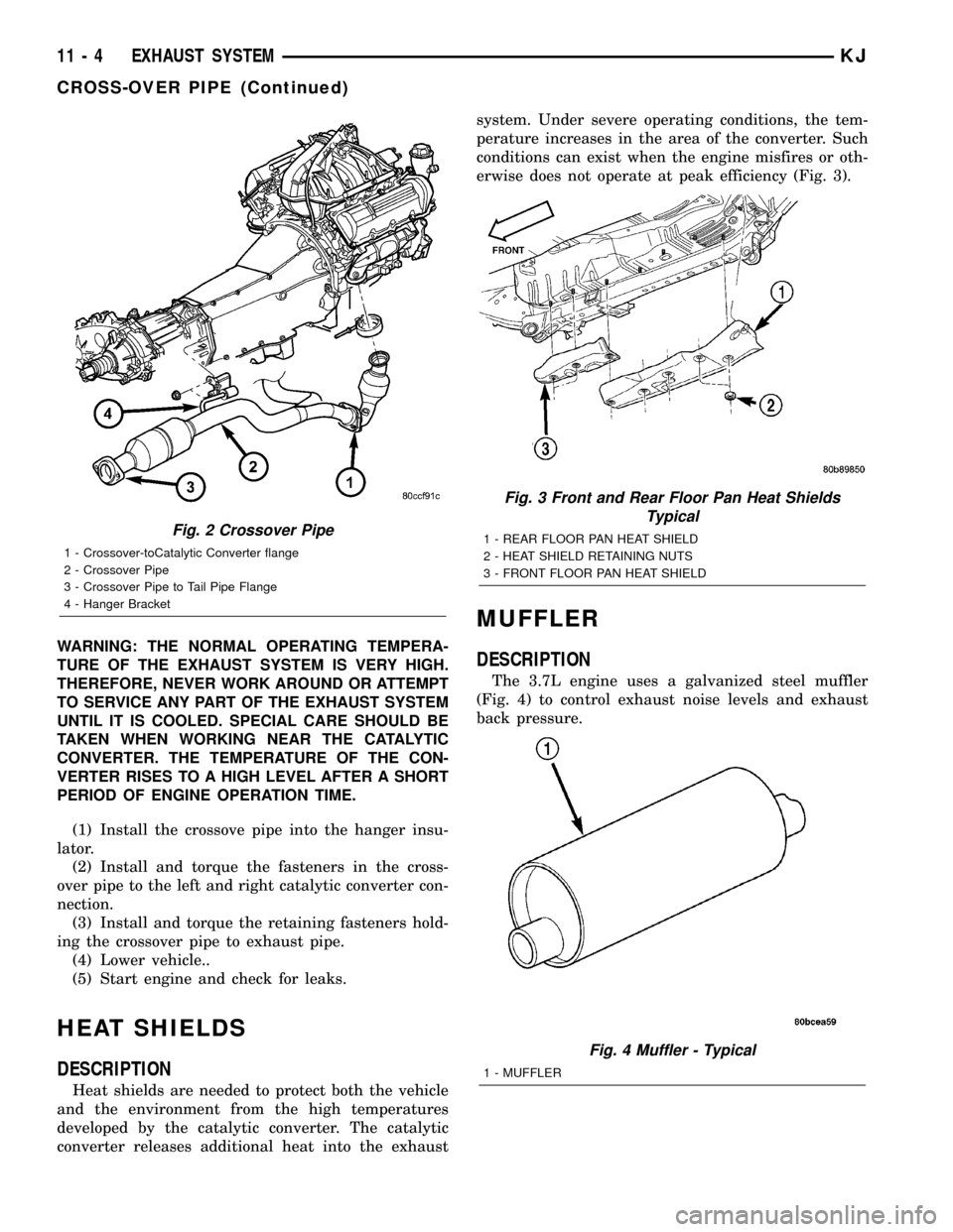
(5) Remove the crossove pipe from the hanger
insulator (Fig. 2).
INSTALLATION
WARNING: IF TORCHES ARE USED WHEN WORK-
ING ON THE EXHAUST SYSTEM, DO NOT ALLOW
THE FLAME NEAR THE FUEL LINES.
Fig. 1 Catalyst Removal
1 - V-Clamp
2 - Catalytic Converter
3 - Flange
4 - Crossover Pipe
5 - T-Bolt
KJEXHAUST SYSTEM 11 - 3
CATALYTIC CONVERTER (Continued)
Page 1365 of 1803
WARNING: THE NORMAL OPERATING TEMPERA-
TURE OF THE EXHAUST SYSTEM IS VERY HIGH.
THEREFORE, NEVER WORK AROUND OR ATTEMPT
TO SERVICE ANY PART OF THE EXHAUST SYSTEM
UNTIL IT IS COOLED. SPECIAL CARE SHOULD BE
TAKEN WHEN WORKING NEAR THE CATALYTIC
CONVERTER. THE TEMPERATURE OF THE CON-
VERTER RISES TO A HIGH LEVEL AFTER A SHORT
PERIOD OF ENGINE OPERATION TIME.
(1) Install the crossove pipe into the hanger insu-
lator.
(2) Install and torque the fasteners in the cross-
over pipe to the left and right catalytic converter con-
nection.
(3) Install and torque the retaining fasteners hold-
ing the crossover pipe to exhaust pipe.
(4) Lower vehicle..
(5) Start engine and check for leaks.
HEAT SHIELDS
DESCRIPTION
Heat shields are needed to protect both the vehicle
and the environment from the high temperatures
developed by the catalytic converter. The catalytic
converter releases additional heat into the exhaustsystem. Under severe operating conditions, the tem-
perature increases in the area of the converter. Such
conditions can exist when the engine misfires or oth-
erwise does not operate at peak efficiency (Fig. 3).
MUFFLER
DESCRIPTION
The 3.7L engine uses a galvanized steel muffler
(Fig. 4) to control exhaust noise levels and exhaust
back pressure.
Fig. 2 Crossover Pipe
1 - Crossover-toCatalytic Converter flange
2 - Crossover Pipe
3 - Crossover Pipe to Tail Pipe Flange
4 - Hanger Bracket
Fig. 3 Front and Rear Floor Pan Heat Shields
Typical
1 - REAR FLOOR PAN HEAT SHIELD
2 - HEAT SHIELD RETAINING NUTS
3 - FRONT FLOOR PAN HEAT SHIELD
Fig. 4 Muffler - Typical
1 - MUFFLER
11 - 4 EXHAUST SYSTEMKJ
CROSS-OVER PIPE (Continued)