2002 JEEP LIBERTY remove seats
[x] Cancel search: remove seatsPage 1263 of 1803
CRANKSHAFT OIL SEAL -
REAR
REMOVAL
NOTE: This procedure can be performed in vehicle.
(1) If being preformed in vehicle, remove the
transmission.
(2) Remove the flexplate (Refer to 9 - ENGINE/
ENGINE BLOCK/FLEX PLATE - REMOVAL).
NOTE: The crankshaft oil seal CAN NOT be reused
after removal.
NOTE: The crankshaft rear oil seal remover Special
Tool 8506 must be installed deeply into the seal.
Continue to tighten the removal tool into the seal
until the tool can not be turned farther. Failure to
install tool correctly the first time will cause tool to
pull free of seal without removing seal from engine.
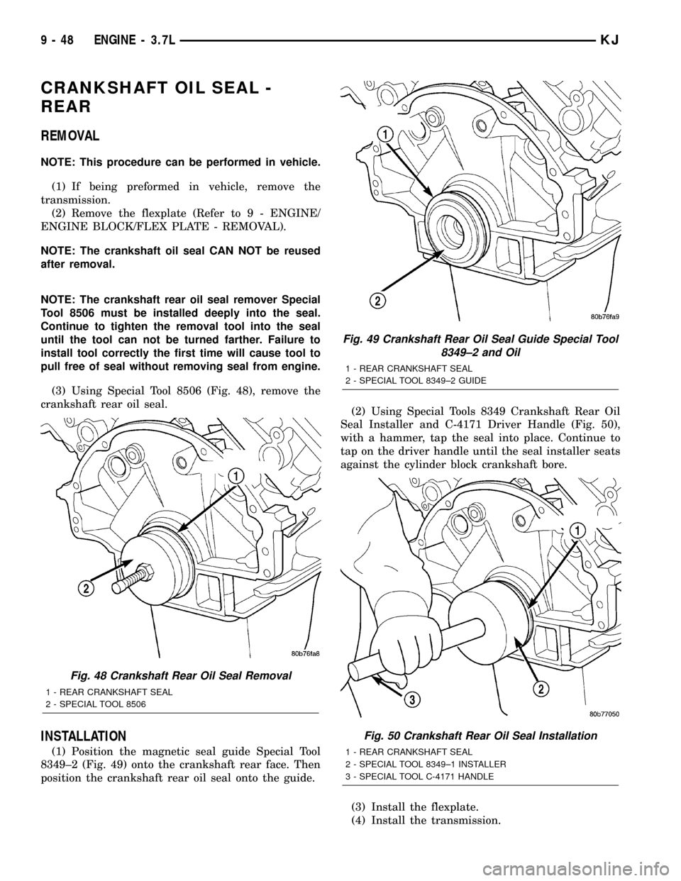
(3) Using Special Tool 8506 (Fig. 48), remove the
crankshaft rear oil seal.
INSTALLATION
(1) Position the magnetic seal guide Special Tool
8349±2 (Fig. 49) onto the crankshaft rear face. Then
position the crankshaft rear oil seal onto the guide.(2) Using Special Tools 8349 Crankshaft Rear Oil
Seal Installer and C-4171 Driver Handle (Fig. 50),
with a hammer, tap the seal into place. Continue to
tap on the driver handle until the seal installer seats
against the cylinder block crankshaft bore.
(3) Install the flexplate.
(4) Install the transmission.
Fig. 48 Crankshaft Rear Oil Seal Removal
1 - REAR CRANKSHAFT SEAL
2 - SPECIAL TOOL 8506
Fig. 49 Crankshaft Rear Oil Seal Guide Special Tool
8349±2 and Oil
1 - REAR CRANKSHAFT SEAL
2 - SPECIAL TOOL 8349±2 GUIDE
Fig. 50 Crankshaft Rear Oil Seal Installation
1 - REAR CRANKSHAFT SEAL
2 - SPECIAL TOOL 8349±1 INSTALLER
3 - SPECIAL TOOL C-4171 HANDLE
9 - 48 ENGINE - 3.7LKJ
Page 1316 of 1803
AIR CLEANER ELEMENT
REMOVAL - 2.4L
Housing removal is not necessary for element (fil-
ter) replacement.
(1) Disconnect air intake duct at side of element
cover.
(2) Pry up 2 spring clips from front of housing
cover (spring clips retain cover to housing).
(3) Release housing cover from locating tabs
located on rear of housing, and remove cover.
(4) Remove air cleaner element (filter) from hous-
ing.
(5) Clean inside of housing before replacing ele-
ment.
INSTALLATION - 2.4L
(1) Install element into housing.
(2) Position housing cover into housing locating
tabs.
(3) Pry up spring clips and lock cover to housing.
(4) Connect air intake duct.
If any air filter, air resonator, air intake tubes or
air filter housing clamps had been loosened or
removed, tighten them to 5 N´m (40 in. lbs.) torque.
CYLINDER HEAD
DESCRIPTION
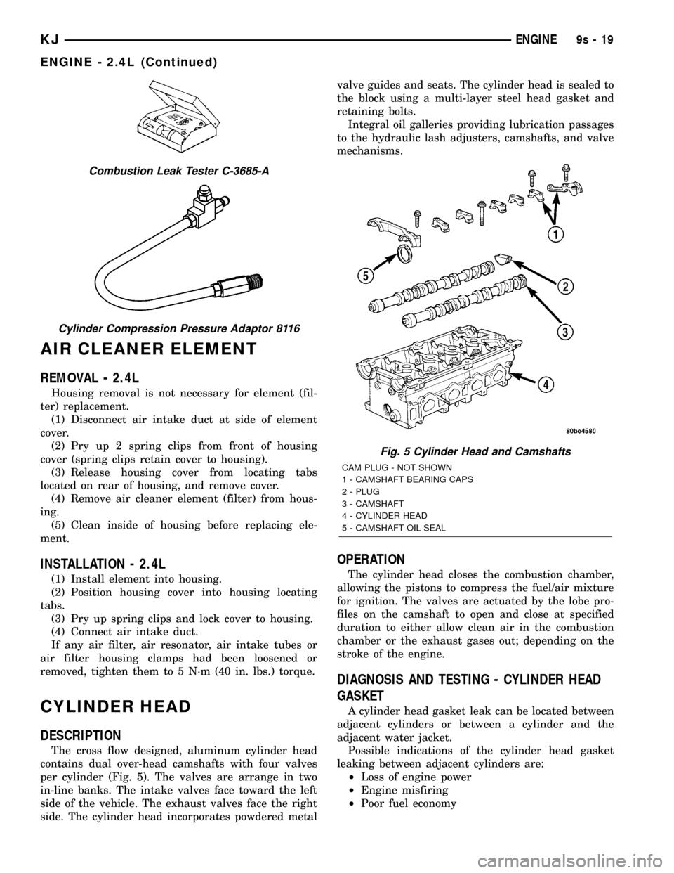
The cross flow designed, aluminum cylinder head
contains dual over-head camshafts with four valves
per cylinder (Fig. 5). The valves are arrange in two
in-line banks. The intake valves face toward the left
side of the vehicle. The exhaust valves face the right
side. The cylinder head incorporates powdered metalvalve guides and seats. The cylinder head is sealed to
the block using a multi-layer steel head gasket and
retaining bolts.
Integral oil galleries providing lubrication passages
to the hydraulic lash adjusters, camshafts, and valve
mechanisms.
OPERATION
The cylinder head closes the combustion chamber,
allowing the pistons to compress the fuel/air mixture
for ignition. The valves are actuated by the lobe pro-
files on the camshaft to open and close at specified
duration to either allow clean air in the combustion
chamber or the exhaust gases out; depending on the
stroke of the engine.
DIAGNOSIS AND TESTING - CYLINDER HEAD
GASKET
A cylinder head gasket leak can be located between
adjacent cylinders or between a cylinder and the
adjacent water jacket.
Possible indications of the cylinder head gasket
leaking between adjacent cylinders are:
²Loss of engine power
²Engine misfiring
²Poor fuel economy
Combustion Leak Tester C-3685-A
Cylinder Compression Pressure Adaptor 8116
Fig. 5 Cylinder Head and Camshafts
CAM PLUG - NOT SHOWN
1 - CAMSHAFT BEARING CAPS
2 - PLUG
3 - CAMSHAFT
4 - CYLINDER HEAD
5 - CAMSHAFT OIL SEAL
KJENGINE9s-19
ENGINE - 2.4L (Continued)
Page 1324 of 1803
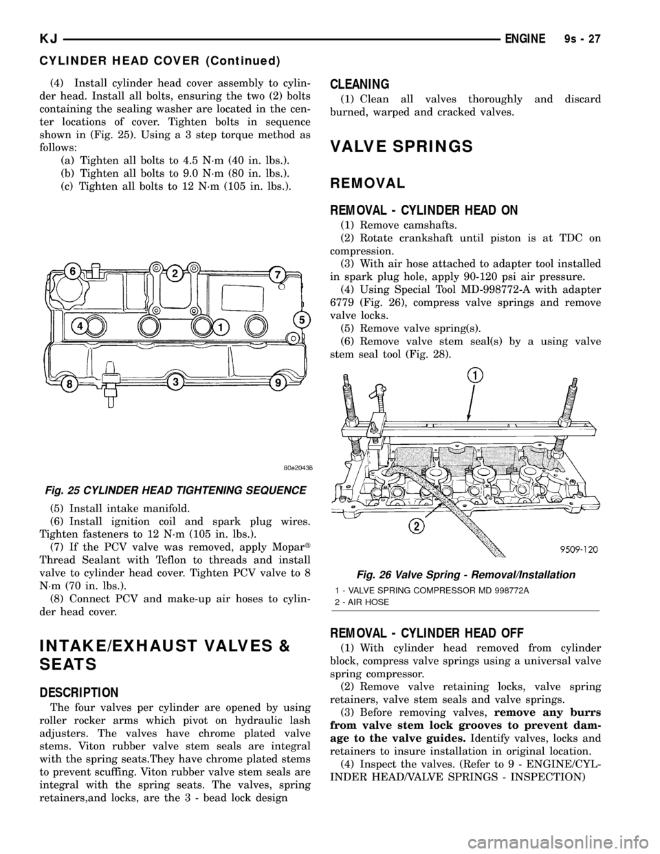
(4) Install cylinder head cover assembly to cylin-
der head. Install all bolts, ensuring the two (2) bolts
containing the sealing washer are located in the cen-
ter locations of cover. Tighten bolts in sequence
shown in (Fig. 25). Using a 3 step torque method as
follows:
(a) Tighten all bolts to 4.5 N´m (40 in. lbs.).
(b) Tighten all bolts to 9.0 N´m (80 in. lbs.).
(c) Tighten all bolts to 12 N´m (105 in. lbs.).
(5) Install intake manifold.
(6) Install ignition coil and spark plug wires.
Tighten fasteners to 12 N´m (105 in. lbs.).
(7) If the PCV valve was removed, apply Mopart
Thread Sealant with Teflon to threads and install
valve to cylinder head cover. Tighten PCV valve to 8
N´m (70 in. lbs.).
(8) Connect PCV and make-up air hoses to cylin-
der head cover.
INTAKE/EXHAUST VALVES &
SEATS
DESCRIPTION
The four valves per cylinder are opened by using
roller rocker arms which pivot on hydraulic lash
adjusters. The valves have chrome plated valve
stems. Viton rubber valve stem seals are integral
with the spring seats.They have chrome plated stems
to prevent scuffing. Viton rubber valve stem seals are
integral with the spring seats. The valves, spring
retainers,and locks, are the 3 - bead lock design
CLEANING
(1) Clean all valves thoroughly and discard
burned, warped and cracked valves.
VALVE SPRINGS
REMOVAL
REMOVAL - CYLINDER HEAD ON
(1) Remove camshafts.
(2) Rotate crankshaft until piston is at TDC on
compression.
(3) With air hose attached to adapter tool installed
in spark plug hole, apply 90-120 psi air pressure.
(4) Using Special Tool MD-998772-A with adapter
6779 (Fig. 26), compress valve springs and remove
valve locks.
(5) Remove valve spring(s).
(6) Remove valve stem seal(s) by a using valve
stem seal tool (Fig. 28).
REMOVAL - CYLINDER HEAD OFF
(1) With cylinder head removed from cylinder
block, compress valve springs using a universal valve
spring compressor.
(2) Remove valve retaining locks, valve spring
retainers, valve stem seals and valve springs.
(3) Before removing valves,remove any burrs
from valve stem lock grooves to prevent dam-
age to the valve guides.Identify valves, locks and
retainers to insure installation in original location.
(4) Inspect the valves. (Refer to 9 - ENGINE/CYL-
INDER HEAD/VALVE SPRINGS - INSPECTION)
Fig. 25 CYLINDER HEAD TIGHTENING SEQUENCE
Fig. 26 Valve Spring - Removal/Installation
1 - VALVE SPRING COMPRESSOR MD 998772A
2 - AIR HOSE
KJENGINE9s-27
CYLINDER HEAD COVER (Continued)
Page 1466 of 1803
BODY
TABLE OF CONTENTS
page page
BODY
WARNING
SAFETY PRECAUTIONS AND WARNINGS . . . 1
DIAGNOSIS AND TESTING
DIAGNOSIS AND TESTING - WATER LEAKS . 2
DIAGNOSIS AND TESTING - WIND NOISE . . . 3
STANDARD PROCEDURE
STANDARD PROCEDURE - BODY
LUBRICATION.........................3
STANDARD PROCEDURE - HEAT STAKING . . 3
SPECIFICATIONS........................4
SPECIAL TOOLS
BODY...............................5BODY STRUCTURE.......................6
HOOD................................119
DOOR - FRONT........................121
DOORS - REAR........................128
SWING GATE..........................135
EXTERIOR............................140
INSTRUMENT PANEL....................147
INTERIOR.............................156
PAINT................................162
SEATS...............................164
STATIONARY GLASS....................172
SUNROOF.............................175
WEATHERSTRIP/SEALS..................185
BODY
WARNING
SAFETY PRECAUTIONS AND WARNINGS
WARNING: EYE PROTECTION SHOULD BE USED
WHEN SERVICING GLASS COMPONENTS. PER-
SONAL INJURY CAN RESULT.
²USE A OSHA APPROVED BREATHING FILTER
WHEN SPRAYING PAINT OR SOLVENTS IN A CON-
FINED AREA. PERSONAL INJURY CAN RESULT.
²AVOID PROLONGED SKIN CONTACT WITH
PETROLEUM OR ALCOHOL±BASED CLEANING
SOLVENTS. PERSONAL INJURY CAN RESULT.
²DO NOT STAND UNDER A HOISTED VEHICLE
THAT IS NOT PROPERLY SUPPORTED ON SAFETY
STANDS. PERSONAL INJURY CAN RESULT.
CAUTION: When holes must be drilled or punched
in an inner body panel, verify depth of space to the
outer body panel, electrical wiring, or other compo-
nents. Damage to vehicle can result.
²Do not weld exterior panels unless combustible
material on the interior of vehicle is removed from
the repair area. Fire or hazardous conditions, can
result.
²Always have a fire extinguisher ready for use
when welding.
²Disconnect the negative (-) cable clamp from
the battery when servicing electrical components
that are live when the ignition is OFF. Damage to
electrical system can result.²Do not use abrasive chemicals or compounds
on painted surfaces. Damage to finish can result.
²Do not use harsh alkaline based cleaning sol-
vents on painted or upholstered surfaces. Damage
to finish or color can result.
²Do not hammer or pound on plastic trim panel
when servicing interior trim. Plastic panels can
break.
DaimlerChrysler Corporation uses many different
types of push-in fasteners to secure the interior and
exterior trim to the body. Most of these fasteners can
be reused to assemble the trim during various repair
procedures. At times, a push-in fastener cannot be
removed without damaging the fastener or the com-
ponent it is holding. If it is not possible to remove a
fastener without damaging a component or body, cut
or break the fastener and use a new one when
installing the component. Never pry or pound on a
plastic or pressed-board trim component. Using a
suitable fork-type prying device, pry the fastener
from the retaining hole behind the component being
removed. When installing, verify fastener alignment
with the retaining hole by hand. Push directly on or
over the fastener until it seats. Apply a low-force pull
to the panel to verify that it is secure.
When it is necessary to remove components to ser-
vice another, it should not be necessary to apply
excessive force or bend a component to remove it.
Before damaging a trim component, verify hidden
fasteners or captured edges holding the component in
place.
KJBODY 23 - 1
Page 1623 of 1803
INSTALLATION
(1) Position the trim panel and seat the retaining
clips.
(2) Install the seat belt turning loop. (Refer to 8 -
ELECTRICAL/RESTRAINTS/SEAT BELT &
RETRACTOR - INSTALLATION)
(3) Install the b-pillar lower trim panel. (Refer to
23 - BODY/INTERIOR/B-PILLAR LOWER TRIM -
INSTALLATION)
CARPETS AND FLOOR MATS
REMOVAL
Front Carpet
(1) Remove front seats. (Refer to 23 - BODY/
SEATS/SEAT - FRONT - REMOVAL)
(2) Remove the floor console. (Refer to 23 - BODY/
INTERIOR/FLOOR CONSOLE - REMOVAL)
(3) Remove the rear seats. (Refer to 23 - BODY/
SEATS/SEAT - REAR - REMOVAL)
(4) Remove the cowl trim panels. (Refer to 23 -
BODY/INTERIOR/COWL TRIM COVER -
REMOVAL)
(5) Remove the b-pillar lower trim. (Refer to 23 -
BODY/INTERIOR/B-PILLAR LOWER TRIM -
REMOVAL)
(6) Remove the jack assembly.
(7) Remove the carpet.
Rear Cargo Carpet
(1) Remove the rivets attaching the cargo hooks to
the floor.
(2) Remove the carpet.
INSTALLATION
Front Carpet
(1) Install the carpet.
(2) Install the jack assembly.
(3) Install the b-pillar lower trim. (Refer to 23 -
BODY/INTERIOR/B-PILLAR LOWER TRIM -
INSTALLATION)
(4) Install the cowl trim panels. (Refer to 23 -
BODY/INTERIOR/COWL TRIM COVER - INSTAL-
LATION)
(5) Install the rear seats. (Refer to 23 - BODY/
SEATS/SEAT - REAR - INSTALLATION)
(6) Install the floor console. (Refer to 23 - BODY/
INTERIOR/FLOOR CONSOLE - INSTALLATION)
(7) Install the front seats. (Refer to 23 - BODY/
SEATS/SEAT - FRONT - INSTALLATION)
Rear Cargo Carpet
(1) Install the carpet and slide under the trim pan-
els.
(2) Install new rivets securing the carpet and
cargo hooks to the floor.
SHIFT BEZEL
REMOVAL
(1) Using a trim stick C-4755 or equivalent, pry
shift bezel out of the floor console.
INSTALLATION
(1) Position the shift bezel and seat the retaining
clips into the floor console.
FLOOR CONSOLE
REMOVAL
(1) Remove the shift bezel, if equipped. (Refer to
23 - BODY/INTERIOR/SHIFT BEZEL - REMOVAL)
(2) Set park brake lever in the up position.
(3) Using a trim stick C-4755 or equivalent, dis-
connect the manual trans shifter boot, if equipped.
(4) Using a trim stick C-4755 or equivalent, dis-
connect the transfer case shifter boot, if equipped.
(5) Remove the four bolts. (Fig. 3)
(6) Lift the console at the back and remove.
INSTALLATION
(1) Position the front of the console and lower the
rear over the shifter and brake levers.
(2) Install the bolts.
(3) Install the shift boots and seat the retainer
clips.
(4) Install the shift bezel. (Refer to 23 - BODY/IN-
TERIOR/SHIFT BEZEL - INSTALLATION)
FLOOR CONSOLE LID LATCH
REMOVAL
(1) Remove the screws and remove the lid.
(2) Remove the screws attaching the lid cover and
remove the latch.
INSTALLATION
(1) Install the latch and the lid cover.
(2) Install the screws attaching the lid cover.
(3) Install the console lid onto the console and
install the screws.
23 - 158 INTERIORKJ
B-PILLAR UPPER TRIM (Continued)
Page 1629 of 1803
SEATS
TABLE OF CONTENTS
page page
HEADREST
REMOVAL............................164
INSTALLATION........................164
HEADREST SLEEVE
REMOVAL............................164
INSTALLATION........................164
SEAT - FRONT
REMOVAL............................165
INSTALLATION........................165
SEAT BACK - FRONT
REMOVAL............................166
INSTALLATION........................166
SEAT BACK RECLINER - FRONT
REMOVAL............................166
INSTALLATION........................166
SEAT BACK COVER - FRONT
REMOVAL............................166
INSTALLATION........................167
SEAT BACK CUSHION - FRONT
REMOVAL............................167
INSTALLATION........................167
SEAT CUSHION - FRONT
REMOVAL............................167
INSTALLATION........................167
SEAT CUSHION COVER - FRONT
REMOVAL............................167
INSTALLATION........................167
SEAT CUSHION SIDE SHIELDS
REMOVAL............................167
INSTALLATION........................167MANUAL SEAT RISER
REMOVAL............................167
INSTALLATION........................168
SEAT TRACK
REMOVAL............................168
INSTALLATION........................168
SEAT - REAR
REMOVAL............................168
INSTALLATION........................168
SEAT BACK - REAR
REMOVAL............................168
INSTALLATION........................168
SEAT BACK COVER - REAR
REMOVAL............................169
INSTALLATION........................169
SEAT BACK CUSHION - REAR
REMOVAL............................170
INSTALLATION........................170
FOLDING REAR SEAT BACK LATCH / LOCK
REMOVAL............................170
INSTALLATION........................170
REAR SEAT BACK LATCH STRIKER
REMOVAL............................170
INSTALLATION........................171
SEAT BACK FRAME - REAR
REMOVAL............................171
INSTALLATION........................171
SEAT CUSHION - REAR
REMOVAL............................171
INSTALLATION........................171
HEADREST
REMOVAL
(1) Depress head restraint release button and lift
head restraint to full up position.
(2) Using a small flat blade, depress tab on right
side head restraint release button and using your
hand, simultaneously press tab on left side head
restraint release button and pull head restraint up to
separate from seat back.
INSTALLATION
(1) Position head restraint in seat back, press tab
on left side head restraint release button and push
down head restraint to secure.
HEADREST SLEEVE
REMOVAL
(1) Remove the headrest. (Refer to 23 - BODY/
SEATS/HEADREST - REMOVAL)
(2) Remove the headrest sleeve cover.
(3) Rotate head restraint sleeve 1/4 turn counter-
clockwise to release retaining tab.
(4) Pull sleeve from seat back frame.
INSTALLATION
(1) Position sleeve in seat back frame.
(2) Rotate head restraint sleeve 1/4 turn clockwise
to engage retaining tab.
(3) Install the headrest sleeve cover.
(4) Install the headrest. (Refer to 23 - BODY/
SEATS/HEADREST - INSTALLATION)
23 - 164 SEATSKJ
Page 1630 of 1803
SEAT - FRONT
REMOVAL
WARNING: DISABLE THE SUPPLEMENTAL
RESTRAINTS SYSTEM BEFORE ATTEMPTING ANY
STEERING WHEEL, STEERING COLUMN, DRIVER
AIRBAG, PASSENGER AIRBAG, SEAT BELT TEN-
SIONER, SIDE CURTAIN AIRBAG, OR INSTRUMENT
PANEL COMPONENT DIAGNOSIS OR SERVICE.
DISCONNECT AND ISOLATE THE BATTERY NEGA-
TIVE (GROUND) CABLE, THEN WAIT TWO MINUTES
FOR THE SYSTEM CAPACITOR TO DISCHARGE
BEFORE PERFORMING FURTHER DIAGNOSIS OR
SERVICE. THIS IS THE ONLY SURE WAY TO DIS-
ABLE THE SUPPLEMENTAL RESTRAINTS SYSTEM.
FAILURE TO TAKE THE PROPER PRECAUTIONS
COULD RESULT IN ACCIDENTAL AIRBAG DEPLOY-
MENT AND POSSIBLE PERSONAL INJURY.
WARNING: DURING AND FOLLOWING ANY SEAT
BELT SERVICE, CAREFULLY INSPECT ALL SEAT
BELTS, BUCKLES, MOUNTING HARDWARE, AND
RETRACTORS FOR PROPER INSTALLATION,
OPERATION, OR DAMAGE. REPLACE ANY BELT
THAT IS CUT, FRAYED, OR TORN. STRAIGHTEN
ANY BELT THAT IS TWISTED. TIGHTEN ANY
LOOSE FASTENERS. REPLACE ANY BELT THAT
HAS A DAMAGED OR INOPERATIVE BUCKLE OR
RETRACTOR. REPLACE ANY BELT THAT HAS A
BENT OR DAMAGED LATCH PLATE OR ANCHOR
PLATE. NEVER ATTEMPT TO REPAIR A SEAT BELT
COMPONENT. ALWAYS REPLACE DAMAGED OR
FAULTY SEAT BELT COMPONENTS WITH THE COR-
RECT, NEW AND UNUSED REPLACEMENT PARTS
LISTED IN THE MOPAR PARTS CATALOG.
(1) Remove the seat belt anchor bolt. (Refer to 8 -
ELECTRICAL/RESTRAINTS/SEAT BELT &
RETRACTOR - REMOVAL)
(2) Slide seat back and remove the front bolts.
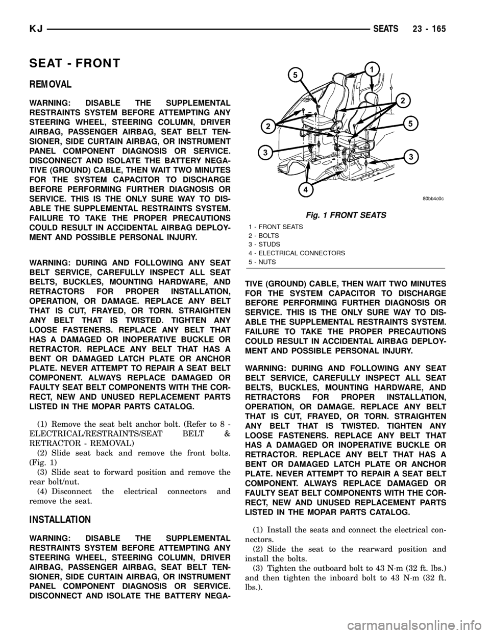
(Fig. 1)
(3) Slide seat to forward position and remove the
rear bolt/nut.
(4) Disconnect the electrical connectors and
remove the seat.
INSTALLATION
WARNING: DISABLE THE SUPPLEMENTAL
RESTRAINTS SYSTEM BEFORE ATTEMPTING ANY
STEERING WHEEL, STEERING COLUMN, DRIVER
AIRBAG, PASSENGER AIRBAG, SEAT BELT TEN-
SIONER, SIDE CURTAIN AIRBAG, OR INSTRUMENT
PANEL COMPONENT DIAGNOSIS OR SERVICE.
DISCONNECT AND ISOLATE THE BATTERY NEGA-TIVE (GROUND) CABLE, THEN WAIT TWO MINUTES
FOR THE SYSTEM CAPACITOR TO DISCHARGE
BEFORE PERFORMING FURTHER DIAGNOSIS OR
SERVICE. THIS IS THE ONLY SURE WAY TO DIS-
ABLE THE SUPPLEMENTAL RESTRAINTS SYSTEM.
FAILURE TO TAKE THE PROPER PRECAUTIONS
COULD RESULT IN ACCIDENTAL AIRBAG DEPLOY-
MENT AND POSSIBLE PERSONAL INJURY.
WARNING: DURING AND FOLLOWING ANY SEAT
BELT SERVICE, CAREFULLY INSPECT ALL SEAT
BELTS, BUCKLES, MOUNTING HARDWARE, AND
RETRACTORS FOR PROPER INSTALLATION,
OPERATION, OR DAMAGE. REPLACE ANY BELT
THAT IS CUT, FRAYED, OR TORN. STRAIGHTEN
ANY BELT THAT IS TWISTED. TIGHTEN ANY
LOOSE FASTENERS. REPLACE ANY BELT THAT
HAS A DAMAGED OR INOPERATIVE BUCKLE OR
RETRACTOR. REPLACE ANY BELT THAT HAS A
BENT OR DAMAGED LATCH PLATE OR ANCHOR
PLATE. NEVER ATTEMPT TO REPAIR A SEAT BELT
COMPONENT. ALWAYS REPLACE DAMAGED OR
FAULTY SEAT BELT COMPONENTS WITH THE COR-
RECT, NEW AND UNUSED REPLACEMENT PARTS
LISTED IN THE MOPAR PARTS CATALOG.
(1) Install the seats and connect the electrical con-
nectors.
(2) Slide the seat to the rearward position and
install the bolts.
(3) Tighten the outboard bolt to 43 N´m (32 ft. lbs.)
and then tighten the inboard bolt to 43 N´m (32 ft.
lbs.).
Fig. 1 FRONT SEATS
1 - FRONT SEATS
2 - BOLTS
3 - STUDS
4 - ELECTRICAL CONNECTORS
5 - NUTS
KJSEATS 23 - 165
Page 1631 of 1803
(4) Slide the seat to the forward position and
install the rear bolt and nut.
(5) Tighten the fasteners to 43 N´m (32 ft. lbs.).
(6) Install the seat belt anchor and bolt. (Refer to
8 - ELECTRICAL/RESTRAINTS/SEAT BELT &
RETRACTOR - INSTALLATION)
SEAT BACK - FRONT
REMOVAL
(1) Remove the seat. (Refer to 23 - BODY/SEATS/
SEAT - FRONT - REMOVAL)
(2) Remove the seat cushion side shields. (Refer to
23 - BODY/SEATS/SEAT CUSHION SIDE SHIELDS
- REMOVAL)
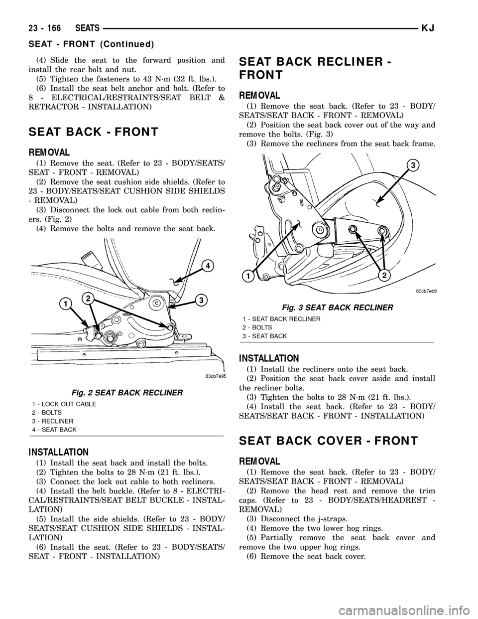
(3) Disconnect the lock out cable from both reclin-
ers. (Fig. 2)
(4) Remove the bolts and remove the seat back.
INSTALLATION
(1) Install the seat back and install the bolts.
(2) Tighten the bolts to 28 N´m (21 ft. lbs.).
(3) Connect the lock out cable to both recliners.
(4) Install the belt buckle. (Refer to 8 - ELECTRI-
CAL/RESTRAINTS/SEAT BELT BUCKLE - INSTAL-
LATION)
(5) Install the side shields. (Refer to 23 - BODY/
SEATS/SEAT CUSHION SIDE SHIELDS - INSTAL-
LATION)
(6) Install the seat. (Refer to 23 - BODY/SEATS/
SEAT - FRONT - INSTALLATION)
SEAT BACK RECLINER -
FRONT
REMOVAL
(1) Remove the seat back. (Refer to 23 - BODY/
SEATS/SEAT BACK - FRONT - REMOVAL)
(2) Position the seat back cover out of the way and
remove the bolts. (Fig. 3)
(3) Remove the recliners from the seat back frame.
INSTALLATION
(1) Install the recliners onto the seat back.
(2) Position the seat back cover aside and install
the recliner bolts.
(3) Tighten the bolts to 28 N´m (21 ft. lbs.).
(4) Install the seat back. (Refer to 23 - BODY/
SEATS/SEAT BACK - FRONT - INSTALLATION)
SEAT BACK COVER - FRONT
REMOVAL
(1) Remove the seat back. (Refer to 23 - BODY/
SEATS/SEAT BACK - FRONT - REMOVAL)
(2) Remove the head rest and remove the trim
caps. (Refer to 23 - BODY/SEATS/HEADREST -
REMOVAL)
(3) Disconnect the j-straps.
(4) Remove the two lower hog rings.
(5) Partially remove the seat back cover and
remove the two upper hog rings.
(6) Remove the seat back cover.
Fig. 2 SEAT BACK RECLINER
1 - LOCK OUT CABLE
2 - BOLTS
3 - RECLINER
4 - SEAT BACK
Fig. 3 SEAT BACK RECLINER
1 - SEAT BACK RECLINER
2 - BOLTS
3 - SEAT BACK
23 - 166 SEATSKJ
SEAT - FRONT (Continued)