2002 JEEP LIBERTY remove seats
[x] Cancel search: remove seatsPage 652 of 1803

(6) Install and tighten the nut that secures the
seat belt turning loop to the height adjuster stud.
Tighten the nut to 34 N´m (25 ft. lbs.).
(7) Fold and snap the trim cover back into place to
conceal the nut that secures the front seat belt turn-
ing loop to the height adjuster on the upper B-pillar.
(8) Position the front seat belt lower anchor to the
bracket on the outboard side of the front seat cushion
frame (Fig. 19).
(9) Install and tighten the screw that secures the
lower anchor to the bracket on the outboard side of
the front seat cushion frame. Tighten the screw to 43
N´m (32 ft. lbs.).
(10) Align the plug that covers the front seat belt
lower anchor screw with the hole near the rear of the
outboard seat side shield. Using hand pressure, press
firmly and evenly on the plug until it snaps into
place.
(11) Do not reconnect the battery negative cable at
this time. The airbag system verification test proce-
dure should be performed following service of any
supplemental restraint system component. (Refer to
8 - ELECTRICAL/RESTRAINTS - STANDARD PRO-
CEDURE - VERIFICATION TEST).
FRONT SEAT BELT BUCKLE
REMOVAL
WARNING: ON VEHICLES EQUIPPED WITH AIR-
BAGS, DISABLE THE SUPPLEMENTAL RESTRAINT
SYSTEM BEFORE ATTEMPTING ANY STEERING
WHEEL, STEERING COLUMN, DRIVER AIRBAG,
PASSENGER AIRBAG, SEAT BELT TENSIONER,
FRONT IMPACT SENSORS, SIDE CURTAIN AIRBAG,
OR INSTRUMENT PANEL COMPONENT DIAGNOSIS
OR SERVICE. DISCONNECT AND ISOLATE THE
BATTERY NEGATIVE (GROUND) CABLE, THEN
WAIT TWO MINUTES FOR THE SYSTEM CAPACI-
TOR TO DISCHARGE BEFORE PERFORMING FUR-
THER DIAGNOSIS OR SERVICE. THIS IS THE ONLY
SURE WAY TO DISABLE THE SUPPLEMENTAL
RESTRAINT SYSTEM. FAILURE TO TAKE THE
PROPER PRECAUTIONS COULD RESULT IN ACCI-
DENTAL AIRBAG DEPLOYMENT AND POSSIBLE
PERSONAL INJURY.WARNING: DURING AND FOLLOWING ANY SEAT
BELT SERVICE, CAREFULLY INSPECT ALL SEAT
BELTS, BUCKLES, MOUNTING HARDWARE, AND
RETRACTORS FOR PROPER INSTALLATION,
OPERATION, OR DAMAGE. REPLACE ANY BELT
THAT IS CUT, FRAYED, OR TORN. STRAIGHTEN
ANY BELT THAT IS TWISTED. TIGHTEN ANY
LOOSE FASTENERS. REPLACE ANY BELT THAT
HAS A DAMAGED OR INOPERATIVE BUCKLE OR
RETRACTOR. REPLACE ANY BELT THAT HAS A
BENT OR DAMAGED LATCH PLATE OR ANCHOR
PLATE. NEVER ATTEMPT TO REPAIR A SEAT BELT
COMPONENT. ALWAYS REPLACE DAMAGED OR
FAULTY SEAT BELT COMPONENTS WITH THE COR-
RECT, NEW AND UNUSED REPLACEMENT PARTS
LISTED IN THE MOPAR PARTS CATALOG.
(1) Disconnect and isolate the battery negative
cable. Wait two minutes for the system capacitor to
discharge before further service.
(2) Remove the front seat and seat track from the
floor panel as a unit. (Refer to 23 - BODY/SEATS/
SEAT - FRONT - REMOVAL).
(3) Disconnect the seat belt switch pigtail wire
connector from the seat wire harness connector on
the seat cushion frame bracket located under the
rear edge of the seat cushion near the inboard side of
the seat (Fig. 21).
Fig. 21 Seat Belt Switch Connector
1 - PIGTAIL WIRE
2 - SEAT WIRE HARNESS
3 - SEAT CUSHION FRAME BRACKET
4 - BODY WIRE HARNESS
5 - INBOARD SEAT TRACK
KJRESTRAINTS 8O - 25
FRONT SEAT BELT & RETRACTOR (Continued)
Page 653 of 1803

(4) Remove the screw that secures the front seat
belt buckle anchor to the bracket near the rear of the
inboard seat track (Fig. 22).
(5) Remove the two screws that secure the inboard
seat cushion side shield to the seat cushion frame.
(6) Remove the two screws that secure the inboard
seat track to the rear inboard corner of the seat cush-
ion frame.
(7) Disconnect the seat belt switch pigtail wire
routing clip from the locating hole in the seat cushion
frame.
(8) Remove the seat belt switch pigtail wire from
between the seat cushion frame and the seat track by
gently prying the inboard seat track away from the
inboard rear corner of the seat cushion frame far
enough to slide the pigtail wire from between them.
(9) Remove the front seat belt buckle from the
inboard seat cushion side shield.
INSTALLATION
WARNING: ON VEHICLES EQUIPPED WITH AIRBAGS,
DISABLE THE SUPPLEMENTAL RESTRAINT SYSTEM
BEFORE ATTEMPTING ANY STEERING WHEEL,
STEERING COLUMN, DRIVER AIRBAG, PASSENGER
AIRBAG, SEAT BELT TENSIONER, FRONT IMPACT
SENSORS, SIDE CURTAIN AIRBAG, OR INSTRUMENT
PANEL COMPONENT DIAGNOSIS OR SERVICE. DIS-
CONNECT AND ISOLATE THE BATTERY NEGATIVE
(GROUND) CABLE, THEN WAIT TWO MINUTES FOR
THE SYSTEM CAPACITOR TO DISCHARGE BEFORE
PERFORMING FURTHER DIAGNOSIS OR SERVICE.
THIS IS THE ONLY SURE WAY TO DISABLE THE SUP-
PLEMENTAL RESTRAINT SYSTEM. FAILURE TO TAKE
THE PROPER PRECAUTIONS COULD RESULT INACCIDENTAL AIRBAG DEPLOYMENT AND POSSIBLE
PERSONAL INJURY.
WARNING: DURING AND FOLLOWING ANY SEAT
BELT SERVICE, CAREFULLY INSPECT ALL SEAT
BELTS, BUCKLES, MOUNTING HARDWARE, AND
RETRACTORS FOR PROPER INSTALLATION,
OPERATION, OR DAMAGE. REPLACE ANY BELT
THAT IS CUT, FRAYED, OR TORN. STRAIGHTEN
ANY BELT THAT IS TWISTED. TIGHTEN ANY
LOOSE FASTENERS. REPLACE ANY BELT THAT
HAS A DAMAGED OR INOPERATIVE BUCKLE OR
RETRACTOR. REPLACE ANY BELT THAT HAS A
BENT OR DAMAGED LATCH PLATE OR ANCHOR
PLATE. NEVER ATTEMPT TO REPAIR A SEAT BELT
COMPONENT. ALWAYS REPLACE DAMAGED OR
FAULTY SEAT BELT COMPONENTS WITH THE COR-
RECT, NEW AND UNUSED REPLACEMENT PARTS
LISTED IN THE MOPAR PARTS CATALOG.
(1) Position the front seat belt buckle to the
inboard seat cushion side shield (Fig. 22).
(2)
Position the seat belt switch pigtail wire between
the seat cushion frame and the seat track by gently pry-
ing the inboard seat track away from the inboard rear
corner of the seat cushion frame far enough to slide the
pigtail wire into position between them.
(3) Engage the seat belt switch pigtail wire routing
clip into the locating hole in the seat cushion frame.
(4) Install and tighten the two screws that secure
the inboard seat track to the rear inboard corner of
the seat cushion frame. Tighten the screws to 28 N´m
(21 ft. lbs.).
(5) Position the inboard seat cushion side shield to
the seat cushion frame.
(6) Install and tighten the two screws that secure
the inboard seat cushion side shield to the seat cush-
ion frame. Tighten the screws to 1 N´m (9 in. lbs.).
(7) Position the front seat belt buckle anchor to
the bracket on the inboard side of the seat track.
(8) Install and tighten the screw that secures the
front seat belt buckle anchor to the bracket on the
inboard side of the seat track. Tighten the screw to
43 N´m (32 ft. lbs.).
(9)
Reconnect the seat belt switch pigtail wire connec-
tor to the seat wire harness connector on the seat cush-
ion frame bracket located under the rear edge of the seat
cushion near the inboard side of the seat (Fig. 21).
(10) Reinstall the front seat and seat track to the
floor panel as a unit. (Refer to 23 - BODY/SEATS/
SEAT - FRONT - INSTALLATION).
(11) Do not reconnect the battery negative cable at
this time. The airbag system verification test proce-
dure should be performed following service of any
supplemental restraint system component. (Refer to
8 - ELECTRICAL/RESTRAINTS - STANDARD PRO-
CEDURE - VERIFICATION TEST).
Fig. 22 Front Seat Belt Buckle Remove/Install
1 - FRONT SEAT BELT BUCKLE
2 - INBOARD SIDE SHIELD
3 - SCREW
4 - PIGTAIL WIRE
8O - 26 RESTRAINTSKJ
FRONT SEAT BELT BUCKLE (Continued)
Page 659 of 1803
REAR CENTER SEAT BELT &
RETRACTOR
REMOVAL
WARNING: DURING AND FOLLOWING ANY SEAT
BELT SERVICE, CAREFULLY INSPECT ALL SEAT
BELTS, BUCKLES, MOUNTING HARDWARE, AND
RETRACTORS FOR PROPER INSTALLATION,
OPERATION, OR DAMAGE. REPLACE ANY BELT
THAT IS CUT, FRAYED, OR TORN. STRAIGHTEN
ANY BELT THAT IS TWISTED. TIGHTEN ANY
LOOSE FASTENERS. REPLACE ANY BELT THAT
HAS A DAMAGED OR INOPERATIVE BUCKLE OR
RETRACTOR. REPLACE ANY BELT THAT HAS A
BENT OR DAMAGED LATCH PLATE OR ANCHOR
PLATE. NEVER ATTEMPT TO REPAIR A SEAT BELT
COMPONENT. ALWAYS REPLACE DAMAGED OR
FAULTY SEAT BELT COMPONENTS WITH THE COR-
RECT, NEW AND UNUSED REPLACEMENT PARTS
LISTED IN THE MOPAR PARTS CATALOG.
(1) Remove the right center seat belt buckle unit
from the floor panel. (Refer to 8 - ELECTRICAL/RE-
STRAINTS/REAR SEAT BELT BUCKLE - REMOV-
AL).
(2) Unlatch and fold the right rear seat back for-
ward and separate the cargo area carpet from the
base of the seat back panel.
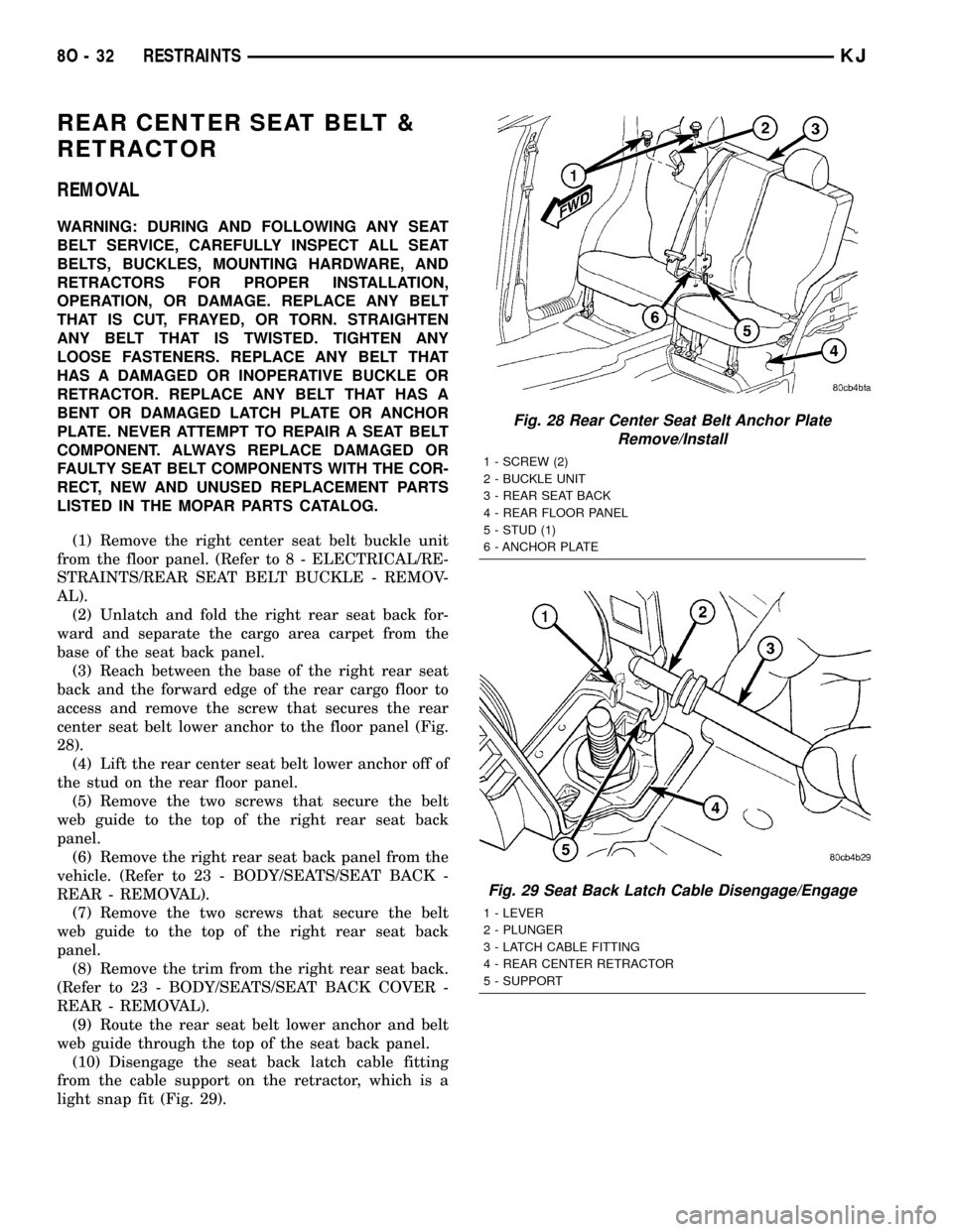
(3) Reach between the base of the right rear seat
back and the forward edge of the rear cargo floor to
access and remove the screw that secures the rear
center seat belt lower anchor to the floor panel (Fig.
28).
(4) Lift the rear center seat belt lower anchor off of
the stud on the rear floor panel.
(5) Remove the two screws that secure the belt
web guide to the top of the right rear seat back
panel.
(6) Remove the right rear seat back panel from the
vehicle. (Refer to 23 - BODY/SEATS/SEAT BACK -
REAR - REMOVAL).
(7) Remove the two screws that secure the belt
web guide to the top of the right rear seat back
panel.
(8) Remove the trim from the right rear seat back.
(Refer to 23 - BODY/SEATS/SEAT BACK COVER -
REAR - REMOVAL).
(9) Route the rear seat belt lower anchor and belt
web guide through the top of the seat back panel.
(10) Disengage the seat back latch cable fitting
from the cable support on the retractor, which is a
light snap fit (Fig. 29).
Fig. 28 Rear Center Seat Belt Anchor Plate
Remove/Install
1 - SCREW (2)
2 - BUCKLE UNIT
3 - REAR SEAT BACK
4 - REAR FLOOR PANEL
5 - STUD (1)
6 - ANCHOR PLATE
Fig. 29 Seat Back Latch Cable Disengage/Engage
1 - LEVER
2 - PLUNGER
3 - LATCH CABLE FITTING
4 - REAR CENTER RETRACTOR
5 - SUPPORT
8O - 32 RESTRAINTSKJ
Page 660 of 1803
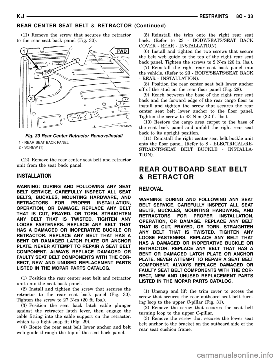
(11) Remove the screw that secures the retractor
to the rear seat back panel (Fig. 30).
(12) Remove the rear center seat belt and retractor
unit from the seat back panel.
INSTALLATION
WARNING: DURING AND FOLLOWING ANY SEAT
BELT SERVICE, CAREFULLY INSPECT ALL SEAT
BELTS, BUCKLES, MOUNTING HARDWARE, AND
RETRACTORS FOR PROPER INSTALLATION,
OPERATION, OR DAMAGE. REPLACE ANY BELT
THAT IS CUT, FRAYED, OR TORN. STRAIGHTEN
ANY BELT THAT IS TWISTED. TIGHTEN ANY
LOOSE FASTENERS. REPLACE ANY BELT THAT
HAS A DAMAGED OR INOPERATIVE BUCKLE OR
RETRACTOR. REPLACE ANY BELT THAT HAS A
BENT OR DAMAGED LATCH PLATE OR ANCHOR
PLATE. NEVER ATTEMPT TO REPAIR A SEAT BELT
COMPONENT. ALWAYS REPLACE DAMAGED OR
FAULTY SEAT BELT COMPONENTS WITH THE COR-
RECT, NEW AND UNUSED REPLACEMENT PARTS
LISTED IN THE MOPAR PARTS CATALOG.
(1) Position the rear center seat belt and retractor
unit onto the seat back panel.
(2) Install and tighten the screw that secures the
retractor to the rear seat back panel (Fig. 30).
Tighten the screw to 27 N´m (20 ft. lbs.).
(3) Position the seat back latch cable plunger
against the retractor latch lever, then engage the
cable fitting into the cable support on the retractor,
which is a light snap fit (Fig. 29).
(4) Route the rear seat belt lower anchor and belt
web guide through the top of the seat back panel.(5) Reinstall the trim onto the right rear seat
back. (Refer to 23 - BODY/SEATS/SEAT BACK
COVER - REAR - INSTALLATION).
(6) Install and tighten the two screws that secure
the belt web guide to the top of the right rear seat
back panel. Tighten the screws to 2 N´m (20 in. lbs.).
(7) Reinstall the right rear seat back panel into
the vehicle. (Refer to 23 - BODY/SEATS/SEAT BACK
- REAR - INSTALLATION).
(8) Position the rear center seat belt lower anchor
off of the stud on the rear floor panel (Fig. 28).
(9) Reach between the base of the right rear seat
back and the forward edge of the rear cargo floor to
install and tighten the screw that secures the rear
center seat belt lower anchor to the floor panel.
Tighten the screw to 43 N´m (32 ft. lbs.).
(10) Restore the cargo area carpet to the base of
the seat back panel and unfold the right rear seat
back to its upright position.
(11) Reinstall the right center seat belt buckle unit
onto the floor panel. (Refer to 8 - ELECTRICAL/RE-
STRAINTS/SEAT BELT BUCKLE - INSTALLA-
TION).
REAR OUTBOARD SEAT BELT
& RETRACTOR
REMOVAL
WARNING: DURING AND FOLLOWING ANY SEAT
BELT SERVICE, CAREFULLY INSPECT ALL SEAT
BELTS, BUCKLES, MOUNTING HARDWARE, AND
RETRACTORS FOR PROPER INSTALLATION,
OPERATION, OR DAMAGE. REPLACE ANY BELT
THAT IS CUT, FRAYED, OR TORN. STRAIGHTEN
ANY BELT THAT IS TWISTED. TIGHTEN ANY
LOOSE FASTENERS. REPLACE ANY BELT THAT
HAS A DAMAGED OR INOPERATIVE BUCKLE OR
RETRACTOR. REPLACE ANY BELT THAT HAS A
BENT OR DAMAGED LATCH PLATE OR ANCHOR
PLATE. NEVER ATTEMPT TO REPAIR A SEAT BELT
COMPONENT. ALWAYS REPLACE DAMAGED OR
FAULTY SEAT BELT COMPONENTS WITH THE COR-
RECT, NEW AND UNUSED REPLACEMENT PARTS
LISTED IN THE MOPAR PARTS CATALOG.
(1) Unsnap and lift the trim cover to access the
screw that secures the rear outboard seat belt turn-
ing loop to the upper C-pillar (Fig. 31).
(2) Remove the screw that secures the seat belt
turning loop to the upper C-pillar.
(3) Remove the screw that secures the lower seat
belt anchor to the bracket on the outboard side of the
rear seat cushion frame.
Fig. 30 Rear Center Retractor Remove/Install
1 - REAR SEAT BACK PANEL
2 - SCREW (1)
KJRESTRAINTS 8O - 33
REAR CENTER SEAT BELT & RETRACTOR (Continued)
Page 710 of 1803

OPERATION
The front check valve provides more than one func-
tion in this application. It serves as a wye connector
fitting between the cowl grille panel and washer noz-
zle sections of the front washer supply hose. It also
prevents washer fluid from draining out of the front
washer supply hoses back to the washer reservoir.
This drain-back would result in a lengthy delay when
the front washer switch is actuated until washer
fluid was dispensed through the front washer noz-
zles, because the washer pump would have to refill
the front washer plumbing from the reservoir to the
nozzles. Finally, the front check valve prevents
washer fluid from siphoning through the front
washer nozzles after the front washer system is
turned Off.
Within the check valve body, a small check valve is
held in place against a seat by a small coiled spring
to restrict flow through the unit until the valve is
unseated by a predetermined inlet fluid pressure.
When the washer pump pressurizes and pumps
washer fluid from the reservoir through the front
washer plumbing, the fluid pressure overrides the
spring pressure applied to the check valve and
unseats the valve, allowing washer fluid to flow
toward the front washer nozzles. When the washer
pump stops operating, spring pressure seats the
check valve and fluid flow in either direction within
the front washer plumbing is prevented.
REMOVAL
(1) Unlatch and open the hood.
(2) Remove both front wiper arms from the wiper
pivots. (Refer to 8 - ELECTRICAL/WIPERS/WASH-
ERS - FRONT/FRONT WIPER ARM - REMOVAL).
(3) Remove the cowl plenum cover/grille panel
from over the cowl plenum. (Refer to 23 - BODY/EX-
TERIOR/COWL GRILLE - REMOVAL).
(4) From the underside of the cowl plenum cover/
grille panel, disconnect the cowl plenum and washer
nozzle hoses from the three barbed nipples of the
front check valve (Fig. 4).
(5) Remove the front check valve from the under-
side of the cowl plenum cover/grille panel.
INSTALLATION
(1) Position the front check valve to the underside
of the cowl plenum cover/grille panel (Fig. 4). Be cer-
tain that the flow direction arrow molded into the
front check valve body is oriented towards the front
washer nozzles.
(2) From the underside of the cowl plenum cover/
grille panel, reconnect the cowl plenum and washer
nozzle hoses to the three barbed nipples of the front
check valve.
(3) Reinstall the cowl plenum cover/grille panel
over the cowl plenum. (Refer to 23 - BODY/EXTERI-
OR/COWL GRILLE - INSTALLATION).
(4) Reinstall both front wiper arms onto the wiper
pivots. (Refer to 8 - ELECTRICAL/FRONT WIPERS/
WASHERS/FRONT WIPER ARM - INSTALLATION).
(5) Close and latch the hood.
Fig. 3 Front Check Valve
1 - INLET NIPPLE
2 - FRONT CHECK VALVE
3 - OUTLET NIPPLE (2)
4 - FLOW DIRECTION ARROW
Fig. 4 Front Check Valve Remove/Install
1 - WASHER NOZZLE HOSE (RIGHT)
2 - FRONT CHECK VALVE
3 - COWL PLENUM WASHER HOSE
4 - ROUTING CLIP
5 - COWL GRILLE COVER (UNDERSIDE)
6 - WASHER NOZZLE HOSE (LEFT)
KJFRONT WIPERS/WASHERS 8R - 9
FRONT CHECK VALVE (Continued)
Page 735 of 1803
REAR WASHER SYSTEM
The washer system components should be
inspected periodically, not just when washer perfor-
mance problems are experienced. This inspection
should include the following points:
(1) Check for ice or other foreign material in the
washer reservoir. If contaminated, clean and flush
the washer system. (Refer to 8 - ELECTRICAL/
REAR WIPERS/WASHERS - CLEANING).
(2) Inspect the washer plumbing for pinched, leak-
ing, deteriorated, or incorrectly routed hoses and
damaged or disconnected hose fittings. Replace dam-
aged or deteriorated hoses and hose fittings. Leaking
washer hoses can sometimes be repaired by cutting
the hose at the leak and splicing it back together
using an in-line connector fitting. Similarly, sections
of deteriorated hose can be cut out and replaced by
splicing in new sections of hose using in-line connec-
tor fittings. Whenever routing a washer hose or a
wire harness containing a washer hose, it must be
routed away from hot, sharp, or moving parts. Also,
sharp bends that might pinch the washer hose must
be avoided.
REAR CHECK VALVE
DESCRIPTION
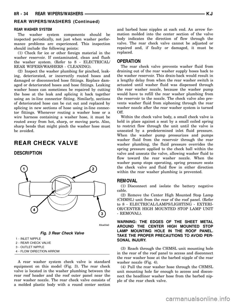
A rear washer system check valve is standard
equipment on this model (Fig. 3). The rear check
valve is located in the washer plumbing between the
rear roof header and the roof outer panel near the
rear washer nozzle. The rear check valve consists of
a molded plastic body with a round center sectionand barbed hose nipples at each end. An arrow for-
mation molded into the center section of the valve
body indicates the direction of flow through the
valve. The rear check valve cannot be adjusted or
repaired and, if faulty or damaged, it must be
replaced.
OPERATION
The rear check valve prevents washer fluid from
draining out of the rear washer supply hoses back to
the washer reservoir. This drain-back would result in
a lengthy delay from when the rear washer switch is
actuated until washer fluid was dispensed through
the rear washer nozzle, because the washer pump
would have to refill the rear washer plumbing from
the reservoir to the nozzle. The check valve also pre-
vents washer fluid from siphoning through the rear
washer nozzle after the rear washer system is turned
Off.
Within the check valve body, a small check valve is
held in place against a seat by a small coiled spring
to restrict flow through the unit until the valve is
unseated by a predetermined inlet fluid pressure.
When the washer pump pressurizes and pumps
washer fluid from the reservoir through the rear
washer plumbing, the fluid pressure overrides the
spring pressure applied to the check ball within the
valve and unseats the valve, allowing washer fluid to
flow toward the rear washer nozzle. When the
washer pump stops operating, spring pressure seats
the check valve and fluid flow in either direction
within the rear washer plumbing is prevented.
REMOVAL
(1) Disconnect and isolate the battery negative
cable.
(2) Remove the Center High Mounted Stop Lamp
(CHMSL) unit from the rear of the roof panel. (Refer
to 8 - ELECTRICAL/LAMPS/LIGHTING - EXTERI-
OR/CENTER HIGH MOUNTED STOP LAMP UNIT
- REMOVAL).
WARNING: THE EDGES OF THE SHEET METAL
AROUND THE CENTER HIGH MOUNTED STOP
LAMP MOUNTING HOLE IN THE ROOF PANEL.
TAKE THE PROPER PRECAUTIONS TO AVOID PER-
SONAL INJURY.
(3) Reach through the CHMSL unit mounting hole
in the rear of the roof panel to access and disconnect
the rear washer hose at the barbed nipple of the rear
washer nozzle (Fig. 4).
(4) Pull the rear washer hose through the CHMSL
unit mounting hole far enough to access and discon-
nect the headliner washer hose from the barbed nip-
ple of the rear check valve.
Fig. 3 Rear Check Valve
1 - INLET NIPPLE
2 - REAR CHECK VALVE
3 - OUTLET NIPPLE
4 - FLOW DIRECTION ARROW
8R - 34 REAR WIPERS/WASHERSKJ
REAR WIPERS/WASHERS (Continued)
Page 1223 of 1803
CONDITION POSSIBLE CAUSES CORRECTION
OIL PUMPING AT RINGS; SPARK
PLUGS FOULING1. Worn or damaged rings. 1. Hone cylinder bores and replace
rings.
2. Carbon in oil ring slots. 2. Replace rings (Refer to 9 -
ENGINE/ENGINE BLOCK/PISTON
RINGS - STANDARD
PROCEDURE).
3. Incorrect ring size installed. 3. Replace rings (Refer to 9 -
ENGINE/ENGINE BLOCK/PISTON
RINGS - STANDARD
PROCEDURE).
4. Worn valve guides. 4. Ream guides and replace valves
(Refer to 9 - ENGINE/CYLINDER
HEAD/INTAKE/EXHAUST VALVES
& SEATS - STANDARD
PROCEDURE).
5. Leaking valve guide seals. 5. Replace valve guide seals.
DIAGNOSIS AND TESTING - CYLINDER
COMPRESSION PRESSURE
The results of a cylinder compression pressure test
can be utilized to diagnose several engine malfunc-
tions.
Ensure the battery is completely charged and the
engine starter motor is in good operating condition.
Otherwise the indicated compression pressures may
not be valid for diagnosis purposes.
(1) Clean the spark plug recesses with compressed
air.
(2) Remove the spark plugs.
(3) Secure the throttle in the wide-open position.
(4) Disable the fuel system (Refer to 14 - FUEL
SYSTEM/FUEL DELIVERY - DESCRIPTION).
(5) Remove the ASD relay (Refer to 8 - ELECTRI-
CAL/IGNITION CONTROL/AUTO SHUT DOWN
RELAY - REMOVAL).
(6) Insert a compression pressure gauge and rotate
the engine with the engine starter motor for three
revolutions.
(7) Record the compression pressure on the 3rd
revolution. Continue the test for the remaining cylin-
ders.
(8) (Refer to 9 - ENGINE - SPECIFICATIONS) for
the correct engine compression pressures.
DIAGNOSIS AND TESTING - CYLINDER
COMBUSTION PRESSURE LEAKAGE
The combustion pressure leakage test provides an
accurate means for determining engine condition.
Combustion pressure leakage testing will detect:
²Exhaust and intake valve leaks (improper seat-
ing).²Leaks between adjacent cylinders or into water
jacket.
²Any causes for combustion/compression pressure
loss.
(1) Check the coolant level and fill as required. DO
NOT install the radiator cap.
(2) Start and operate the engine until it attains
normal operating temperature, then turn the engine
OFF.
(3) Remove the spark plugs.
(4) Remove the oil filler cap.
(5) Remove the air cleaner.
(6) Calibrate the tester according to the manufac-
turer's instructions. The shop air source for testing
should maintain 483 kPa (70 psi) minimum, 1,379
kPa (200 psi) maximum and 552 kPa (80 psi) recom-
mended.
(7) Perform the test procedures on each cylinder
according to the tester manufacturer's instructions.
Set piston of cylinder to be tested at TDC compres-
sion,While testing, listen for pressurized air escaping
through the throttle body, tailpipe and oil filler cap
opening. Check for bubbles in the radiator coolant.
All gauge pressure indications should be equal,
with no more than 25% leakage.
FOR EXAMPLE:At 552 kPa (80 psi) input pres-
sure, a minimum of 414 kPa (60 psi) should be main-
tained in the cylinder.
Refer to CYLINDER COMBUSTION PRESSURE
LEAKAGE DIAGNOSIS CHART .
9 - 8 ENGINE - 3.7LKJ
ENGINE - 3.7L (Continued)
Page 1237 of 1803
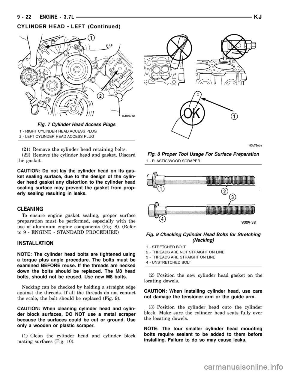
(21) Remove the cylinder head retaining bolts.
(22) Remove the cylinder head and gasket. Discard
the gasket.
CAUTION: Do not lay the cylinder head on its gas-
ket sealing surface, due to the design of the cylin-
der head gasket any distortion to the cylinder head
sealing surface may prevent the gasket from prop-
erly sealing resulting in leaks.
CLEANING
To ensure engine gasket sealing, proper surface
preparation must be performed, especially with the
use of aluminum engine components (Fig. 8). (Refer
to 9 - ENGINE - STANDARD PROCEDURE)
INSTALLATION
NOTE: The cylinder head bolts are tightened using
a torque plus angle procedure. The bolts must be
examined BEFORE reuse. If the threads are necked
down the bolts should be replaced. The M8 head
bolts, should not be reused. Use new M8 bolts.
Necking can be checked by holding a straight edge
against the threads. If all the threads do not contact
the scale, the bolt should be replaced (Fig. 9).
CAUTION: When cleaning cylinder head and cylin-
der block surfaces, DO NOT use a metal scraper
because the surfaces could be cut or ground. Use
only a wooden or plastic scraper.
(1) Clean the cylinder head and cylinder block
mating surfaces (Fig. 10).(2) Position the new cylinder head gasket on the
locating dowels.
CAUTION: When installing cylinder head, use care
not damage the tensioner arm or the guide arm.
(3) Position the cylinder head onto the cylinder
block. Make sure the cylinder head seats fully over
the locating dowels.
NOTE: The four smaller cylinder head mounting
bolts require sealant to be added to them before
installing. Failure to do so may cause leaks.
Fig. 7 Cylinder Head Access Plugs
1 - RIGHT CYLINDER HEAD ACCESS PLUG
2 - LEFT CYLINDER HEAD ACCESS PLUG
Fig. 8 Proper Tool Usage For Surface Preparation
1 - PLASTIC/WOOD SCRAPER
Fig. 9 Checking Cylinder Head Bolts for Stretching
(Necking)
1 - STRETCHED BOLT
2 - THREADS ARE NOT STRAIGHT ON LINE
3 - THREADS ARE STRAIGHT ON LINE
4 - UNSTRETCHED BOLT
9 - 22 ENGINE - 3.7LKJ
CYLINDER HEAD - LEFT (Continued)