2002 JEEP LIBERTY coolant level
[x] Cancel search: coolant levelPage 1110 of 1803
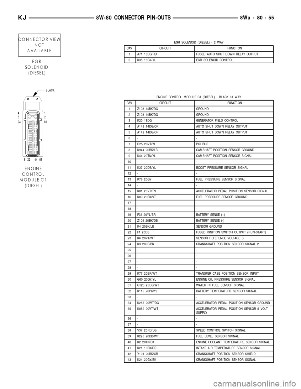
EGR SOLENOID (DIESEL)-2WAY
CAV CIRCUIT FUNCTION
1 A71 18DG/RD FUSED AUTO SHUT DOWN RELAY OUTPUT
2 K35 18GY/YL EGR SOLENOID CONTROL
ENGINE CONTROL MODULE C1 (DIESEL) - BLACK 81 WAY
CAV CIRCUIT FUNCTION
1 Z108 14BK/DG GROUND
2 Z108 14BK/DG GROUND
3 K20 18DG GENERATOR FIELD CONTROL
4 A142 14DG/OR AUTO SHUT DOWN RELAY OUTPUT
5 A142 14DG/OR AUTO SHUT DOWN RELAY OUTPUT
6- -
7 D25 20VT/YL PCI BUS
8 K944 20BK/LB CAMSHAFT POSITION SENSOR GROUND
9 K44 20TN/YL CAMSHAFT POSITION SENSOR SIGNAL
10 - -
11 K37 20DB/YL BOOST PRESSURE SENSOR SIGNAL
12 - -
13 K78 20GY FUEL PRESSURE SENSOR SIGNAL
14 - -
15 K81 20VT/TN ACCELERATOR PEDAL POSITION SENSOR SIGNAL
16 K80 20BK/VT FUEL PRESSURE SENSOR GROUND
17 - -
18 - -
19 F92 20YL/BR BATTERY SENSE (+)
20 Z109 20BK/DB BATTERY SENSE (-)
21 K4 20BK/LB SENSOR GROUND
22 F1 20DB FUSED IGNITION SWITCH OUTPUT (RUN-START)
23 K6 20VT/WT SENSOR REFERENCE VOLTAGE B
24 K3 20LB/BK CRANKSHAFT POSITION SENSOR SIGNAL 2
25 - -
26 - -
27 - -
28 - -
29 K77 20BR/WT TRANSFER CASE POSITION SENSOR INPUT
30 G60 20GY/YL ENGINE OIL PRESSURE SENSOR SIGNAL
31 G123 20DG/WT WATER IN FUEL SENSOR SIGNAL
32 K118 20PK/YL BATTERY TEMPERATURE SENSOR SIGNAL
33 - -
34 K255 20WT/DG ACCELERATOR PEDAL POSITION SENSOR GROUND
35 K852 20VT/WT ACCELERATOR PEDAL POSITION SENSOR 5 VOLT
SUPPLY
36 - -
37 - -
38 V37 20RD/LG SPEED CONTROL SWITCH SIGNAL
39 K226 20DB/WT FUEL LEVEL SENSOR SIGNAL
40 K2 20TN/BK ENGINE COOLANT TEMPERATURE SENSOR SIGNAL
41 K21 18BK/RD INTAKE AIR TEMPERATURE SENSOR SIGNAL
42 Y101 20BK/OR CRANKSHAFT POSITION SENSOR SHIELD
43 K24 20GY/BK CRANKSHAFT POSITION SENSOR SIGNAL 1
KJ8W-80 CONNECTOR PIN-OUTS8Wa-80-55
Page 1112 of 1803
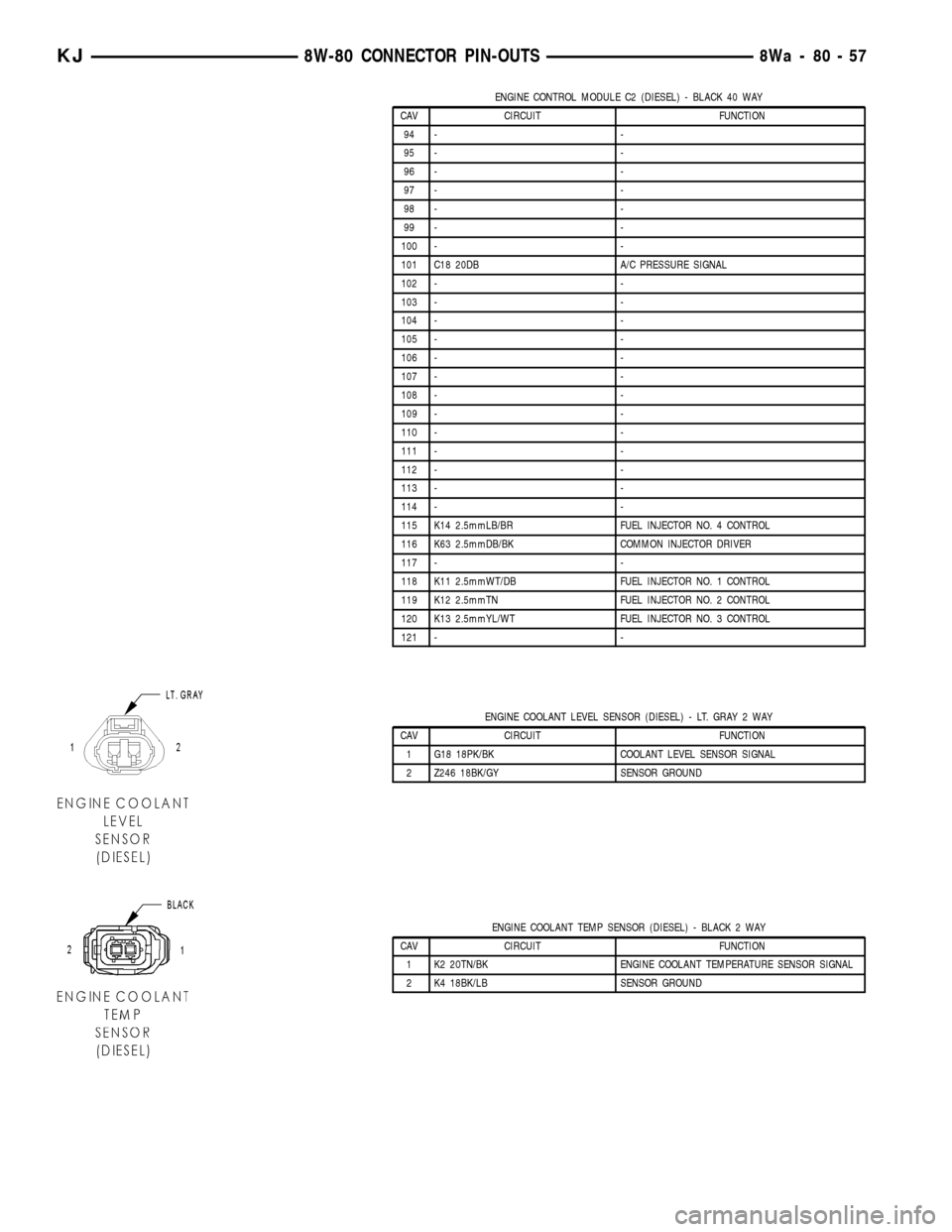
ENGINE CONTROL MODULE C2 (DIESEL) - BLACK 40 WAY
CAV CIRCUIT FUNCTION
94 - -
95 - -
96 - -
97 - -
98 - -
99 - -
100 - -
101 C18 20DB A/C PRESSURE SIGNAL
102 - -
103 - -
104 - -
105 - -
106 - -
107 - -
108 - -
109 - -
110 - -
111 - -
112 - -
113 - -
114 - -
115 K14 2.5mmLB/BR FUEL INJECTOR NO. 4 CONTROL
116 K63 2.5mmDB/BK COMMON INJECTOR DRIVER
117 - -
118 K11 2.5mmWT/DB FUEL INJECTOR NO. 1 CONTROL
119 K12 2.5mmTN FUEL INJECTOR NO. 2 CONTROL
120 K13 2.5mmYL/WT FUEL INJECTOR NO. 3 CONTROL
121 - -
ENGINE COOLANT LEVEL SENSOR (DIESEL) - LT. GRAY 2 WAY
CAV CIRCUIT FUNCTION
1 G18 18PK/BK COOLANT LEVEL SENSOR SIGNAL
2 Z246 18BK/GY SENSOR GROUND
ENGINE COOLANT TEMP SENSOR (DIESEL) - BLACK 2 WAY
CAV CIRCUIT FUNCTION
1 K2 20TN/BK ENGINE COOLANT TEMPERATURE SENSOR SIGNAL
2 K4 18BK/LB SENSOR GROUND
KJ8W-80 CONNECTOR PIN-OUTS8Wa-80-57
Page 1119 of 1803
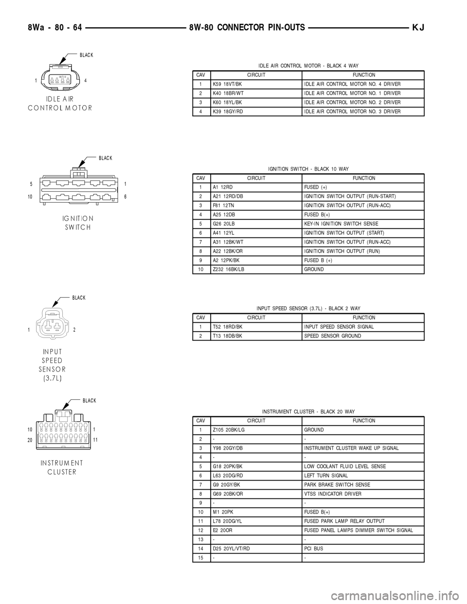
IDLE AIR CONTROL MOTOR - BLACK 4 WAY
CAV CIRCUIT FUNCTION
1 K59 18VT/BK IDLE AIR CONTROL MOTOR NO. 4 DRIVER
2 K40 18BR/WT IDLE AIR CONTROL MOTOR NO. 1 DRIVER
3 K60 18YL/BK IDLE AIR CONTROL MOTOR NO. 2 DRIVER
4 K39 18GY/RD IDLE AIR CONTROL MOTOR NO. 3 DRIVER
IGNITION SWITCH - BLACK 10 WAY
CAV CIRCUIT FUNCTION
1 A1 12RD FUSED (+)
2 A21 12RD/DB IGNITION SWITCH OUTPUT (RUN-START)
3 F81 12TN IGNITION SWITCH OUTPUT (RUN-ACC)
4 A25 12DB FUSED B(+)
5 G26 20LB KEY-IN IGNITION SWITCH SENSE
6 A41 12YL IGNITION SWITCH OUTPUT (START)
7 A31 12BK/WT IGNITION SWITCH OUTPUT (RUN-ACC)
8 A22 12BK/OR IGNITION SWITCH OUTPUT (RUN)
9 A2 12PK/BK FUSED B (+)
10 Z232 16BK/LB GROUND
INPUT SPEED SENSOR (3.7L) - BLACK 2 WAY
CAV CIRCUIT FUNCTION
1 T52 18RD/BK INPUT SPEED SENSOR SIGNAL
2 T13 18DB/BK SPEED SENSOR GROUND
INSTRUMENT CLUSTER - BLACK 20 WAY
CAV CIRCUIT FUNCTION
1 Z105 20BK/LG GROUND
2- -
3 Y98 20GY/DB INSTRUMENT CLUSTER WAKE UP SIGNAL
4- -
5 G18 20PK/BK LOW COOLANT FLUID LEVEL SENSE
6 L63 20DG/RD LEFT TURN SIGNAL
7 G9 20GY/BK PARK BRAKE SWITCH SENSE
8 G69 20BK/OR VTSS INDICATOR DRIVER
9- -
10 M1 20PK FUSED B(+)
11 L78 20DG/YL FUSED PARK LAMP RELAY OUTPUT
12 E2 20OR FUSED PANEL LAMPS DIMMER SWITCH SIGNAL
13 - -
14 D25 20YL/VT/RD PCI BUS
15 - -
8Wa - 80 - 64 8W-80 CONNECTOR PIN-OUTSKJ
Page 1159 of 1803
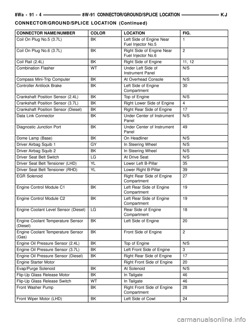
CONNECTOR NAME/NUMBER COLOR LOCATION FIG.
Coil On Plug No.5 (3.7L) BK Left Side of Engine Near
Fuel Injector No.51
Coil On Plug No.6 (3.7L) BK Right Side of Engine Near
Fuel Injector No.62
Coil Rail (2.4L) BK Right Side of Engine 11, 12
Combination Flasher WT Under Left Side of
Instrument PanelN/S
Compass Mini-Trip Computer BK At Overhead Console N/S
Controller Antilock Brake BK Left Side of Engine
Compartment30
Crankshaft Position Sensor (2.4L) BK Top of Engine N/S
Crankshaft Position Sensor (3.7L) BK Right Lower Side of Engine 4
Crankshaft Position Sensor (Diesel) BK Right Rear Side of Engine 17
Data Link Connector BK Under Center of Instrument
PanelN/S
Diagnostic Junction Port BK Under Center of Instrument
Panel49
Dome Lamp (Base) BK On Headliner N/S
Driver Airbag Squib 1 GY In Steering Wheel N/S
Driver Airbag Squib 2 BK In Steering Wheel N/S
Driver Seat Belt Switch LG At Drive Seat N/S
Driver Seat Belt Tensioner (LHD) YL Lower Left B-Pillar 35
Driver Seat Belt Tensioner (RHD) YL Lower Right B-Pillar 39
EGR Solenoid Right Rear Side of Engine
Compartment27
Engine Control Module C1 BK Left Rear Side of Engine
Compartment19
Engine Control Module C2 BK Left Rear Side of Engine
Compartment19
Engine Coolant Level Sensor (Diesel) LG Rear Side of Engine
Compartment18
Engine Coolant Temperature Sensor
(Diesel)BK Left Side of Engine 20
Engine Coolant Temperature Sensor
(Gas)BK Front Side of Engine 2
Engine Oil Pressure Sensor (2.4L) BK Top of Engine N/S
Engine Oil Pressure Sensor (3.7L) BK Left Front Side of Engine 3
Engine Oil Pressure Sensor (Diesel) BK Right Rear Side of Engine 17
Engine Starter Motor Right Front Side of Engine 20
Evap/Purge Solenoid BK At Solenoid N/S
Flip-Up Glass Release Motor BK In Tailgate 46
Flip-Up Glass Release Switch WT In Tailgate 46
Front Washer Pump BK Right Front Side of Engine
Compartment28
Front Wiper Motor (LHD) BK Left Side of Cowl 24
8Wa - 91 - 4 8W-91 CONNECTOR/GROUND/SPLICE LOCATIONKJ
CONNECTOR/GROUND/SPLICE LOCATION (Continued)
Page 1223 of 1803
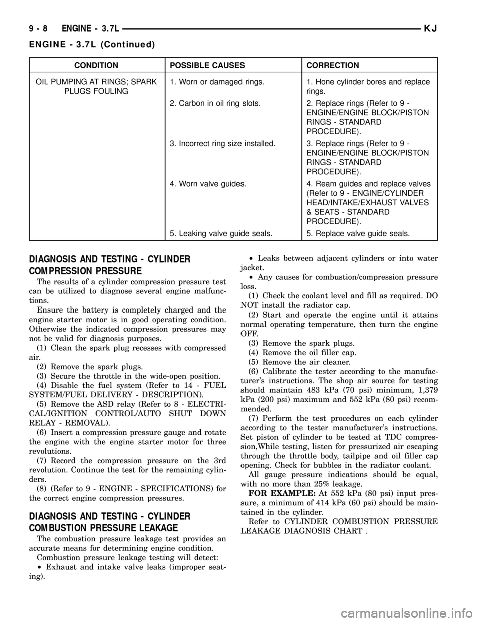
CONDITION POSSIBLE CAUSES CORRECTION
OIL PUMPING AT RINGS; SPARK
PLUGS FOULING1. Worn or damaged rings. 1. Hone cylinder bores and replace
rings.
2. Carbon in oil ring slots. 2. Replace rings (Refer to 9 -
ENGINE/ENGINE BLOCK/PISTON
RINGS - STANDARD
PROCEDURE).
3. Incorrect ring size installed. 3. Replace rings (Refer to 9 -
ENGINE/ENGINE BLOCK/PISTON
RINGS - STANDARD
PROCEDURE).
4. Worn valve guides. 4. Ream guides and replace valves
(Refer to 9 - ENGINE/CYLINDER
HEAD/INTAKE/EXHAUST VALVES
& SEATS - STANDARD
PROCEDURE).
5. Leaking valve guide seals. 5. Replace valve guide seals.
DIAGNOSIS AND TESTING - CYLINDER
COMPRESSION PRESSURE
The results of a cylinder compression pressure test
can be utilized to diagnose several engine malfunc-
tions.
Ensure the battery is completely charged and the
engine starter motor is in good operating condition.
Otherwise the indicated compression pressures may
not be valid for diagnosis purposes.
(1) Clean the spark plug recesses with compressed
air.
(2) Remove the spark plugs.
(3) Secure the throttle in the wide-open position.
(4) Disable the fuel system (Refer to 14 - FUEL
SYSTEM/FUEL DELIVERY - DESCRIPTION).
(5) Remove the ASD relay (Refer to 8 - ELECTRI-
CAL/IGNITION CONTROL/AUTO SHUT DOWN
RELAY - REMOVAL).
(6) Insert a compression pressure gauge and rotate
the engine with the engine starter motor for three
revolutions.
(7) Record the compression pressure on the 3rd
revolution. Continue the test for the remaining cylin-
ders.
(8) (Refer to 9 - ENGINE - SPECIFICATIONS) for
the correct engine compression pressures.
DIAGNOSIS AND TESTING - CYLINDER
COMBUSTION PRESSURE LEAKAGE
The combustion pressure leakage test provides an
accurate means for determining engine condition.
Combustion pressure leakage testing will detect:
²Exhaust and intake valve leaks (improper seat-
ing).²Leaks between adjacent cylinders or into water
jacket.
²Any causes for combustion/compression pressure
loss.
(1) Check the coolant level and fill as required. DO
NOT install the radiator cap.
(2) Start and operate the engine until it attains
normal operating temperature, then turn the engine
OFF.
(3) Remove the spark plugs.
(4) Remove the oil filler cap.
(5) Remove the air cleaner.
(6) Calibrate the tester according to the manufac-
turer's instructions. The shop air source for testing
should maintain 483 kPa (70 psi) minimum, 1,379
kPa (200 psi) maximum and 552 kPa (80 psi) recom-
mended.
(7) Perform the test procedures on each cylinder
according to the tester manufacturer's instructions.
Set piston of cylinder to be tested at TDC compres-
sion,While testing, listen for pressurized air escaping
through the throttle body, tailpipe and oil filler cap
opening. Check for bubbles in the radiator coolant.
All gauge pressure indications should be equal,
with no more than 25% leakage.
FOR EXAMPLE:At 552 kPa (80 psi) input pres-
sure, a minimum of 414 kPa (60 psi) should be main-
tained in the cylinder.
Refer to CYLINDER COMBUSTION PRESSURE
LEAKAGE DIAGNOSIS CHART .
9 - 8 ENGINE - 3.7LKJ
ENGINE - 3.7L (Continued)
Page 1245 of 1803

(9) Using Special Tool 8516 Valve Spring Compres-
sor, install the rocker arms and the hydraulic lash
adjusters.
(10) Install the cylinder head cover. Refer to Cylin-
der Head Cover in this Section.
CYLINDER HEAD - RIGHT
DESCRIPTION
DESCRIPTION - CYLINDER HEAD
The cylinder heads are made of an aluminum alloy.
The cylinder head features two valves per cylinder
with pressed in powdered metal valve guides. The
cylinder heads also provide enclosures for the timing
chain drain, necessitating unique left and right cylin-
der heads.
DESCRIPTION - VALVE GUIDES
The valve guides are made of powered metal and
are pressed into the cylinder head. The guides are
not replaceable or serviceable, and valve guide ream-
ing is not recommended. If the guides are worn
beyond acceptable limits, replace the cylinder heads.
DESCRIPTION
The valves are made of heat resistant steel and
have chrome plated stems to prevent scuffing. Each
valve is actuated by a roller rocker arm which pivots
on a stationary lash adjuster. All valves use three
bead lock keepers to retain the springs and promote
valve rotation.
DIAGNOSIS AND TESTING
DIAGNOSIS AND TESTING - HYDRAULIC LASH
ADJUSTER
A tappet-like noise may be produced from several
items. Check the following items.
(1) Engine oil level too high or too low. This may
cause aerated oil to enter the adjusters and cause
them to be spongy.
(2) Insufficient running time after rebuilding cylin-
der head. Low speed running up to 1 hour may be
required.
(3) Turn engine off and let set for a few minutes
before restarting. Repeat this several times after
engine has reached normal operating temperature.
(4) Low oil pressure.
(5) The oil restrictor in cylinder head gasket or the
oil passage to the cylinder head is plugged with
debris.(6) Air ingested into oil due to broken or cracked
oil pump pick up.
(7) Worn valve guides.
(8) Rocker arm ears contacting valve spring
retainer.
(9) Rocker arm loose, adjuster stuck or at maxi-
mum extension and still leaves lash in the system.
(10) Oil leak or excessive cam bore wear in cylin-
der head.
(11) Faulty lash adjuster.
²Check lash adjusters for sponginess while
installed in cylinder head and cam on camshaft at
base circle. Depress part of rocker arm over adjuster.
Normal adjusters should feel very firm. Spongy
adjusters can be bottomed out easily.
²Remove suspected lash adjusters, and replace.
²Before installation, make sure adjusters are at
least partially full of oil. This can be verified by little
or no plunger travel when lash adjuster is depressed.
DIAGNOSIS AND TESTING - CYLINDER HEAD
GASKET
A cylinder head gasket leak can be located between
adjacent cylinders or between a cylinder and the
adjacent water jacket.
Possible indications of the cylinder head gasket
leaking between adjacent cylinders are:
²Loss of engine power
²Engine misfiring
²Poor fuel economy
Possible indications of the cylinder head gasket
leaking between a cylinder and an adjacent water
jacket are:
²Engine overheating
²Loss of coolant
²Excessive steam (white smoke) emitting from
exhaust
²Coolant foaming
CYLINDER-TO-CYLINDER LEAKAGE TEST
To determine if an engine cylinder head gasket is
leaking between adjacent cylinders, follow the proce-
dures in Cylinder Compression Pressure Test (Refer
to 9 - ENGINE - DIAGNOSIS AND TESTING). An
engine cylinder head gasket leaking between adja-
cent cylinders will result in approximately a 50±70%
reduction in compression pressure.
CYLINDER-TO-WATER JACKET LEAKAGE TEST
WARNING: USE EXTREME CAUTION WHEN THE
ENGINE IS OPERATING WITH COOLANT PRES-
SURE CAP REMOVED.
9 - 30 ENGINE - 3.7LKJ
VALVE SPRINGS (Continued)
Page 1284 of 1803

(11) Bleed fuel system. Refer to FUEL SYSTEM.
(12) Remove fuel rail.
(13) Remove throttle body assembly and mounting
bracket.
(14) Drain cooling system below coolant tempera-
ture level. Refer to COOLING SYSTEM.
(15) Remove the heater hoses from the engine
front cover and the heater core.
(16) Unclip and remove heater hoses and tubes
from intake manifold.
(17) Remove coolant temperature sensor. Refer to
FUEL SYSTEM.
(18) Remove intake manifold retaining fasteners in
reverse order of tightening sequence.
(19) Remove intake manifold.
INSTALLATION
(1) Install intake manifold gaskets.
(2) Install intake manifold.
(3) Install intake manifold retaining bolts and
tighten in sequence shown in to 12 N´m (105 in. lbs.).
(4) Install left and right radio suppressor straps.
(5) Install throttle body assembly.
(6) Install throttle cable bracket.
(7) Connect throttle cable and speed control cable
to throttle body.
(8) Install fuel rail.
(9) Install ignition coil towers.
(10) Position and install heater hoses and tubes
onto intake manifold.
(11) Install the heater hoses to the heater core and
engine front cover.
(12) Connect electrical connectors for the following
components:
²Manifold Absolute Pressure (MAP) Sensor
²Intake Air Temperature (IAT) Sensor
²Throttle Position (TPS) Sensor
²Coolant Temperature (CTS) Sensor
²Idle Air Control (IAC) Motor
²Ignition coil towers
²Fuel injectors
(13) Install top oil dipstick tube retaining bolt and
ground strap.
(14) Connect generator electrical connections.
(15) Connect Vapor purge hose, Brake booster
hose, Speed control servo hose, Positive crankcase
ventilation (PCV) hose.
(16) Fill cooling system.
(17) Install resonator assembly and air inlet hose.
(18) Connect negative cable to battery.
EXHAUST MANIFOLD
DESCRIPTION
The exhaust manifolds (Fig. 87) are log style with
a patented flow enhancing design to maximize perfor-
mance. The exhaust manifolds are made of high sili-
con molybdenum cast iron. A perforated core graphite
exhaust manifold gasket is used to improve sealing
to the cylinder head. The exhaust manifolds are cov-
ered by a three layer laminated heat shield for ther-
mal protection and noise reduction. The heat shields
(Fig. 88) are fastened with a torque prevailing nut
that is backed off slightly to allow for the thermal
expansion of the exhaust manifold.
REMOVAL
RIGHT EXHAUST MANIFOLD
(1) Disconnect the negative cable from the battery.
(2) Raise and support the vehicle.
(3) Remove the bolts and nuts attaching the
exhaust pipe to the engine exhaust manifold.
(4) Lower the vehicle.
(5) Remove the exhaust heat shield (Fig. 89).
(6) Remove bolts, nuts and washers attaching
manifold to cylinder head.
(7) Remove manifold and gasket from the cylinder
head.
Fig. 87 EXHAUST MANIFOLDS
1 - LEFT SIDE EXHAUST MANIFOLD
2 - RIGHT SIDE EXHAUST MANIFOLD
KJENGINE - 3.7L 9 - 69
INTAKE MANIFOLD (Continued)
Page 1300 of 1803
ENGINE - 2.4L
DESCRIPTION
The 2.4 Liter (148 cu. in.) in-line four cylinder
engine is a double over head camshaft with hydraulic
lifters and four valve per cylinder design. The engine
is free-wheeling; meaning it has provisions for piston-
to-valve clearance. However valve-to-valve interference
can occur, if camshafts are rotated independently.
The cylinders are numbered from front of the
engine to the rear. The firing order is 1±3±4±2.
The engine identification number is located on the
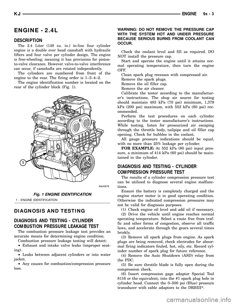
rear of the cylinder block (Fig. 1).
DIAGNOSIS AND TESTING
DIAGNOSIS AND TESTING - CYLINDER
COMBUSTION PRESSURE LEAKAGE TEST
The combustion pressure leakage test provides an
accurate means for determining engine condition.
Combustion pressure leakage testing will detect:
²Exhaust and intake valve leaks (improper seat-
ing).
²Leaks between adjacent cylinders or into water
jacket.
²Any causes for combustion/compression pressure
loss.WARNING: DO NOT REMOVE THE PRESSURE CAP
WITH THE SYSTEM HOT AND UNDER PRESSURE
BECAUSE SERIOUS BURNS FROM COOLANT CAN
OCCUR.
Check the coolant level and fill as required. DO
NOT install the pressure cap.
Start and operate the engine until it attains nor-
mal operating temperature, then turn the engine
OFF.
Clean spark plug recesses with compressed air.
Remove the spark plugs.
Remove the oil filler cap.
Remove the air cleaner.
Calibrate the tester according to the manufactur-
er's instructions. The shop air source for testing
should maintain 483 kPa (70 psi) minimum, 1,379
kPa (200 psi) maximum, with 552 kPa (80 psi) rec-
ommended.
Perform the test procedures on each cylinder
according to the tester manufacturer's instructions.
While testing, listen for pressurized air escaping
through the throttle body, tailpipe and oil filler cap
opening. Check for bubbles in the coolant.
All gauge pressure indications should be equal,
with no more than 25% leakage per cylinder.
FOR EXAMPLE:At 552 kPa (80 psi) input pres-
sure, a minimum of 414 kPa (60 psi) should be main-
tained in the cylinder.
DIAGNOSIS AND TESTING - CYLINDER
COMPRESSION PRESSURE TEST
The results of a cylinder compression pressure test
can be utilized to diagnose several engine malfunc-
tions.
Ensure the battery is completely charged and the
engine starter motor is in good operating condition.
Otherwise the indicated compression pressures may
not be valid for diagnosis purposes.
(1) Check engine oil level and add oil if necessary.
(2) Drive the vehicle until engine reaches normal
operating temperature. Select a route free from traf-
fic and other forms of congestion, observe all traffic
laws, and accelerate through the gears several times
briskly.
(3) Remove all spark plugs from engine. As spark
plugs are being removed, check electrodes for abnor-
mal firing indicators fouled, hot, oily, etc. Record cyl-
inder number of spark plug for future reference.
(4) Remove the Auto Shutdown (ASD) relay from
the PDC.
(5) Be sure throttle blade is fully open during the
compression check.
(6) Insert compression gage adaptor Special Tool
8116 or the equivalent, into the #1 spark plug hole in
cylinder head. Connect the 0±500 psi (Blue) pressure
transducer with cable adaptors to the DRBIIIt.
Fig. 1 ENGINE IDENTIFICATION
1 - ENGINE IDENTIFICATION
KJENGINE9s-3