2002 JEEP LIBERTY Crankcase breather
[x] Cancel search: Crankcase breatherPage 1249 of 1803

(6) Position the camshaft drive gear into the tim-
ing chain aligning the V6 mark between the two
marked chain links (Two links marked during remov-
al).
(7) Using Special Tool 8428 Camshaft Wrench,
rotate the camshaft until the camshaft sprocket
dowel is aligned with the slot in the camshaft
sprocket. Install the sprocket onto the camshaft.
CAUTION: Remove excess oil from camshaft
sprocket bolt. Failure to do so can cause bolt over-
torque resulting in bolt failure.
(8) Remove excess oil from camshaft sprocket bolt,
then install the camshaft sprocket retaining bolt and
hand tighten.
(9) Remove timing chain wedge special tool 8379.
(10) Using Special Tool 6958 spanner wrench with
adapter pins 8346, torque the camshaft sprocket
retaining bolt to 122 N´m (90 ft. lbs.).
(11) Install the camshaft position sensor.
(12) Install the cylinder head cover.
CYLINDER HEAD COVER(S)
REMOVAL
(1) Disconnect battery negative cable.
(2) Remove air cleaner assembly, resonator assem-
bly and air inlet hose.
(3) Drain cooling system, below the level of the
heater hoses. Refer to COOLING SYSTEM.(4) Remove accessory drive belt.
(5) Remove air conditioning compressor retaining
bolts and move compressor to the left.
(6) Remove heater hoses.
(7) Disconnect injector and ignition coil connectors.
(8) Disconnect and remove positive crankcase ven-
tilation (PCV) hose.
(9) Remove oil fill tube.
(10) Un-clip injector and ignition coil harness and
move away from cylinder head cover.
(11) Remove right rear breather tube and filter
assembly.
(12) Remove cylinder head cover retaining bolts.
(13) Remove cylinder head cover.
INSTALLATION
CAUTION: Do not use harsh cleaners to clean the
cylinder head covers. Severe damage to covers
may occur.
NOTE: The gasket may be used again, provided no
cuts, tears, or deformation has occurred.
(1) Clean cylinder head cover and both sealing sur-
faces. Inspect and replace gasket as necessary.
(2) Tighten cylinder head cover bolts and double
ended studs to 12 N´m (105 in. lbs).
(3) Install right rear breather tube and filter
assembly.
(4) Connect injector, ignition coil electrical connec-
tors and harness retaining clips.
(5) Install the oil fill tube.
(6) Install PCV hose.
(7) Install heater hoses.
(8) Install air conditioning compressor retaining
bolts.
(9) Install accessory drive belt
(10) Fill Cooling system
(11) Install air cleaner assembly, resonator assem-
bly and air inlet hose.
(12) Connect battery negative cable.
INTAKE/EXHAUST VALVES &
SEATS
STANDARD PROCEDURE - REFACING
NOTE: Valve seats that are worn or burned can be
reworked, provided that correct angle and seat
width are maintained. Otherwise the cylinder head
must be replaced.
Fig. 23 Camshaft Bearing Caps Tightening
Sequence
9 - 34 ENGINE - 3.7LKJ
CAMSHAFT(S) (Continued)
Page 1735 of 1803

(4) Carefully install vapor/vacuum lines to LDP,
and install hose to LDP filter.The vapor/vacuum
lines and hoses must be firmly connected.
Check the vapor/vacuum lines at the LDP, LDP
filter and EVAP canister duty cycle purge sole-
noid for damage or leaks. If a leak is present, a
Diagnostic Trouble Code (DTC) may be set.
ORVR
DESCRIPTION
The ORVR (On-Board Refueling Vapor Recovery)
system consists of a unique fuel tank, flow manage-
ment valve, fluid control valve, one-way check valve
and vapor canister (Fig. 1).
OPERATION
The ORVR (On-Board Refueling Vapor Recovery)
system is used to remove excess fuel tank vapors.
This is done while the vehicle is being refueled. Cer-
tain ORVR components can be found in (Fig. 1).
Fuel flowing into the fuel filler tube (approx. 1º
I.D.) creates an aspiration effect drawing air into the
fuel fill tube. During refueling, the fuel tank is
vented to the EVAP canister to capture escaping
vapors. With air flowing into the filler tube, there are
no fuel vapors escaping to the atmosphere. Once the
refueling vapors are captured by the EVAP canister,the vehicle's computer controlled purge system draws
vapor out of the canister for the engine to burn. The
vapor flow is metered by the purge solenoid so that
there is no, or minimal impact on driveability or
tailpipe emissions.
As fuel starts to flow through the fuel fill tube, it
opens the normally closed check valve and enters the
fuel tank. Vapor or air is expelled from the tank
through the control valve and on to the vapor canis-
ter. Vapor is absorbed in the EVAP canister until
vapor flow in the lines stops. This stoppage occurs
following fuel shut-off, or by having the fuel level in
the tank rise high enough to close the control valve.
This control valve contains a float that rises to seal
the large diameter vent path to the EVAP canister.
At this point in the refueling process, fuel tank pres-
sure increases, the check valve closes (preventing liq-
uid fuel from spiting back at the operator), and fuel
then rises up the fuel filler tube to shut off the dis-
pensing nozzle.
PCV VALVE
DESCRIPTION
2.4L
The 2.4L 4-cylinder engine is equipped with a
closed crankcase ventilation system and a Positive
Crankcase Ventilation (PCV) valve.
This system consists of:
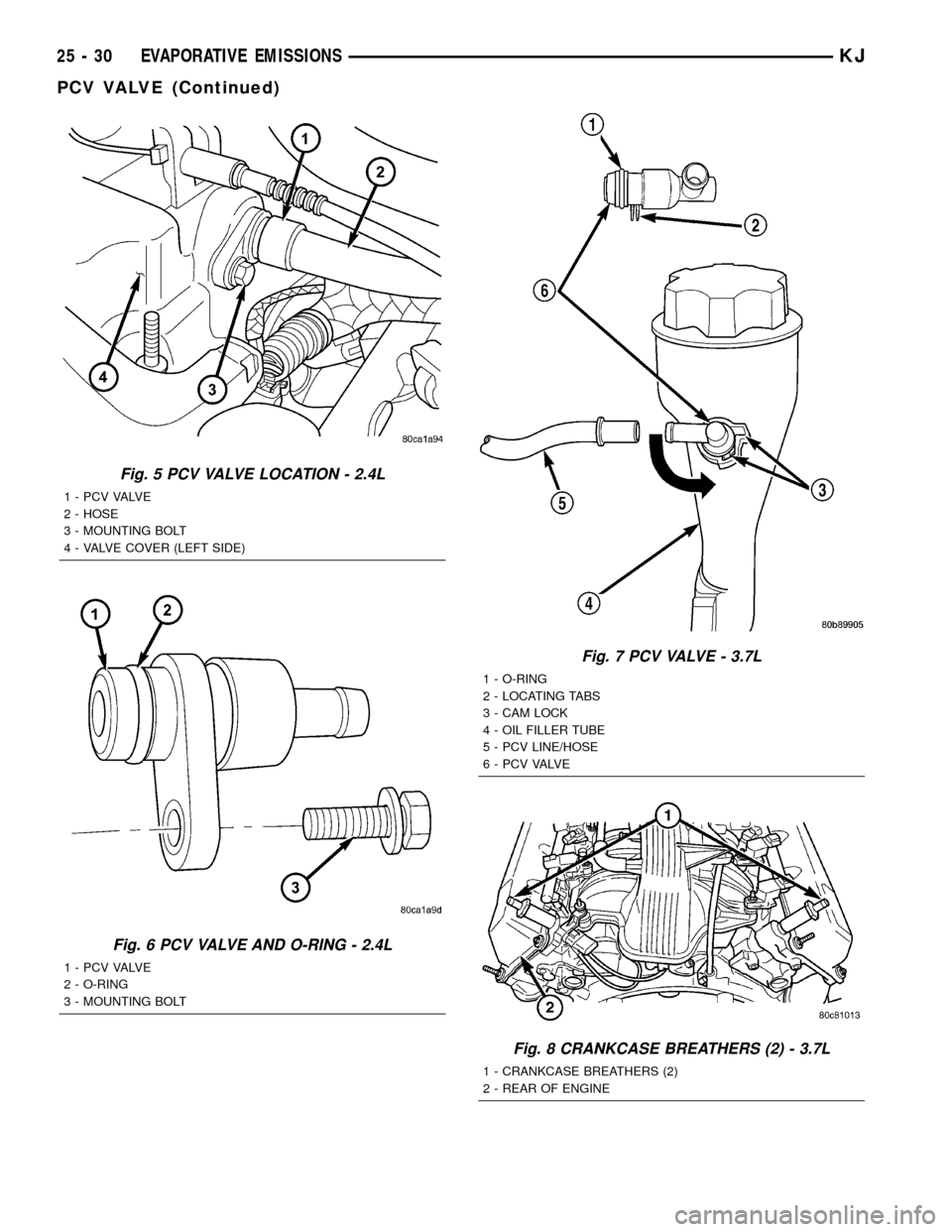
²a PCV valve attached to the left/front side of the
valve cover (Fig. 5). It is secured with 1 bolt. An
o-ring is used to seal valve to valve cover (Fig. 6).
²the air cleaner housing
²tubes and hoses to connect the system compo-
nents.
3.7L
The 3.7L V-6 engine is equipped with a closed
crankcase ventilation system and a Positive Crank-
case Ventilation (PCV) valve.
This system consists of:
²a PCV valve mounted to the oil filler housing
(Fig. 7). The PCV valve is sealed to the oil filler
housing with an o-ring.
²the air cleaner housing
²two interconnected breathers threaded into the
rear of each cylinder head (Fig. 8).
²tubes and hoses to connect the system compo-
nents.
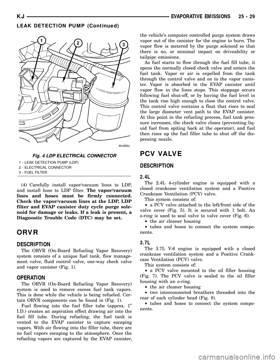
Fig. 4 LDP ELECTRICAL CONNECTOR
1 - LEAK DETECTION PUMP (LDP)
2 - ELECTRICAL CONNECTOR
3 - FUEL FILTER
KJEVAPORATIVE EMISSIONS 25 - 29
LEAK DETECTION PUMP (Continued)
Page 1736 of 1803

Fig. 5 PCV VALVE LOCATION - 2.4L
1 - P C V VA LV E
2 - HOSE
3 - MOUNTING BOLT
4 - VALVE COVER (LEFT SIDE)
Fig. 6 PCV VALVE AND O-RING - 2.4L
1 - P C V VA LV E
2 - O-RING
3 - MOUNTING BOLT
Fig. 7 PCV VALVE - 3.7L
1 - O-RING
2 - LOCATING TABS
3 - CAM LOCK
4 - OIL FILLER TUBE
5 - PCV LINE/HOSE
6 - P C V VA LV E
Fig. 8 CRANKCASE BREATHERS (2) - 3.7L
1 - CRANKCASE BREATHERS (2)
2 - REAR OF ENGINE
25 - 30 EVAPORATIVE EMISSIONSKJ
PCV VALVE (Continued)
Page 1738 of 1803

(13) If vacuum is not present, disconnect each PCV
system hose at top of each crankcase breather (Fig.
8). Check for obstructions or restrictions.
(14) If vacuum is still not present, remove each
PCV system crankcase breather (Fig. 8) from each
cylinder head. Check for obstructions or restrictions.
If plugged, replace breather. Tighten breather to 12
N´m (106 in. lbs.) torque. Do not attempt to clean
breather
(15) If vacuum is still not present, disconnect each
PCV system hose at each fitting and check for
obstructions or restrictions.
REMOVAL
2.4L
The PCV valve is attached to the left/front side of
the valve cover (Fig. 5). It is secured with 1 bolt. An
o-ring is used to seal valve to valve cover (Fig. 6).
(1) Remove hose from valve (Fig. 5). Check condi-
tion of hose.
(2) Remove 1 bolt.
(3) Remove PCV valve from valve cover.
(4) Check condition of valve o-ring.
3.7L
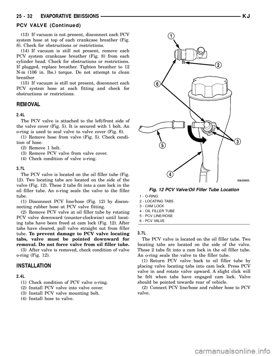
The PCV valve is located on the oil filler tube (Fig.
12). Two locating tabs are located on the side of the
valve (Fig. 12). These 2 tabs fit into a cam lock in the
oil filler tube. An o-ring seals the valve to the filler
tube.
(1) Disconnect PCV line/hose (Fig. 12) by discon-
necting rubber hose at PCV valve fitting.
(2) Remove PCV valve at oil filler tube by rotating
PCV valve downward (counter-clockwise) until locat-
ing tabs have been freed at cam lock (Fig. 12). After
tabs have cleared, pull valve straight out from filler
tube.To prevent damage to PCV valve locating
tabs, valve must be pointed downward for
removal. Do not force valve from oil filler tube.
(3) After valve is removed, check condition of valve
o-ring (Fig. 12).
INSTALLATION
2.4L
(1) Check condition of PCV valve o-ring.
(2) Install PCV valve into valve cover.
(3) Install PCV valve mounting bolt.
(4) Install hose to valve.3.7L
The PCV valve is located on the oil filler tube. Two
locating tabs are located on the side of the valve.
These 2 tabs fit into a cam lock in the oil filler tube.
An o-ring seals the valve to the filler tube.
(1) Return PCV valve back to oil filler tube by
placing valve locating tabs into cam lock. Press PCV
valve in and rotate valve upward. A slight click will
be felt when tabs have engaged cam lock. Valve
should be pointed towards rear of vehicle.
(2) Connect PCV line/hose and rubber hose to PCV
valve.
Fig. 12 PCV Valve/Oil Filler Tube Location
1 - O-RING
2 - LOCATING TABS
3 - CAM LOCK
4 - OIL FILLER TUBE
5 - PCV LINE/HOSE
6 - P C V VA LV E
25 - 32 EVAPORATIVE EMISSIONSKJ
PCV VALVE (Continued)