2002 JEEP LIBERTY Starter
[x] Cancel search: StarterPage 1159 of 1803
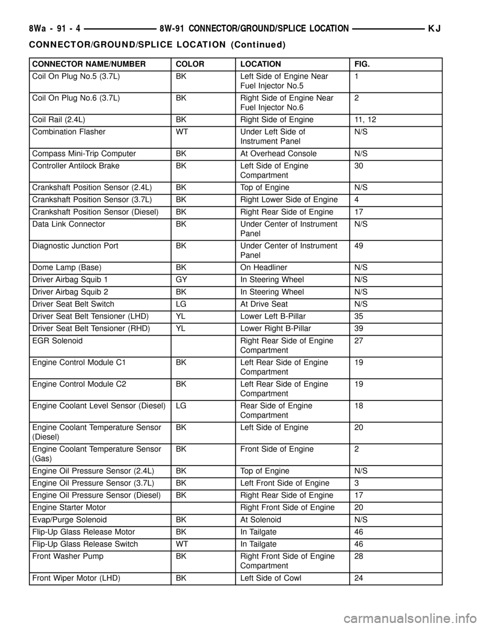
CONNECTOR NAME/NUMBER COLOR LOCATION FIG.
Coil On Plug No.5 (3.7L) BK Left Side of Engine Near
Fuel Injector No.51
Coil On Plug No.6 (3.7L) BK Right Side of Engine Near
Fuel Injector No.62
Coil Rail (2.4L) BK Right Side of Engine 11, 12
Combination Flasher WT Under Left Side of
Instrument PanelN/S
Compass Mini-Trip Computer BK At Overhead Console N/S
Controller Antilock Brake BK Left Side of Engine
Compartment30
Crankshaft Position Sensor (2.4L) BK Top of Engine N/S
Crankshaft Position Sensor (3.7L) BK Right Lower Side of Engine 4
Crankshaft Position Sensor (Diesel) BK Right Rear Side of Engine 17
Data Link Connector BK Under Center of Instrument
PanelN/S
Diagnostic Junction Port BK Under Center of Instrument
Panel49
Dome Lamp (Base) BK On Headliner N/S
Driver Airbag Squib 1 GY In Steering Wheel N/S
Driver Airbag Squib 2 BK In Steering Wheel N/S
Driver Seat Belt Switch LG At Drive Seat N/S
Driver Seat Belt Tensioner (LHD) YL Lower Left B-Pillar 35
Driver Seat Belt Tensioner (RHD) YL Lower Right B-Pillar 39
EGR Solenoid Right Rear Side of Engine
Compartment27
Engine Control Module C1 BK Left Rear Side of Engine
Compartment19
Engine Control Module C2 BK Left Rear Side of Engine
Compartment19
Engine Coolant Level Sensor (Diesel) LG Rear Side of Engine
Compartment18
Engine Coolant Temperature Sensor
(Diesel)BK Left Side of Engine 20
Engine Coolant Temperature Sensor
(Gas)BK Front Side of Engine 2
Engine Oil Pressure Sensor (2.4L) BK Top of Engine N/S
Engine Oil Pressure Sensor (3.7L) BK Left Front Side of Engine 3
Engine Oil Pressure Sensor (Diesel) BK Right Rear Side of Engine 17
Engine Starter Motor Right Front Side of Engine 20
Evap/Purge Solenoid BK At Solenoid N/S
Flip-Up Glass Release Motor BK In Tailgate 46
Flip-Up Glass Release Switch WT In Tailgate 46
Front Washer Pump BK Right Front Side of Engine
Compartment28
Front Wiper Motor (LHD) BK Left Side of Cowl 24
8Wa - 91 - 4 8W-91 CONNECTOR/GROUND/SPLICE LOCATIONKJ
CONNECTOR/GROUND/SPLICE LOCATION (Continued)
Page 1166 of 1803
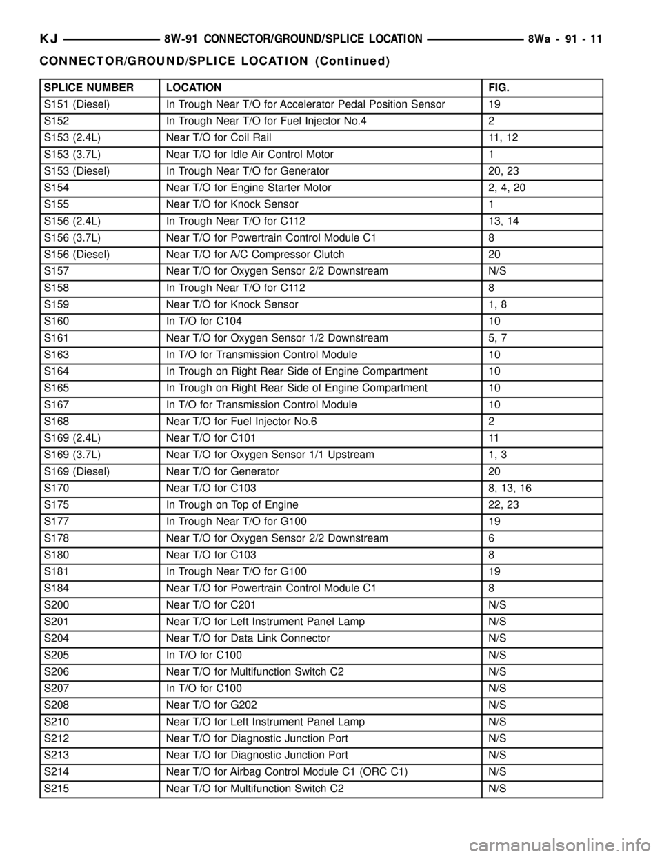
SPLICE NUMBER LOCATION FIG.
S151 (Diesel) In Trough Near T/O for Accelerator Pedal Position Sensor 19
S152 In Trough Near T/O for Fuel Injector No.4 2
S153 (2.4L) Near T/O for Coil Rail 11, 12
S153 (3.7L) Near T/O for Idle Air Control Motor 1
S153 (Diesel) In Trough Near T/O for Generator 20, 23
S154 Near T/O for Engine Starter Motor 2, 4, 20
S155 Near T/O for Knock Sensor 1
S156 (2.4L) In Trough Near T/O for C112 13, 14
S156 (3.7L) Near T/O for Powertrain Control Module C1 8
S156 (Diesel) Near T/O for A/C Compressor Clutch 20
S157 Near T/O for Oxygen Sensor 2/2 Downstream N/S
S158 In Trough Near T/O for C112 8
S159 Near T/O for Knock Sensor 1, 8
S160 In T/O for C104 10
S161 Near T/O for Oxygen Sensor 1/2 Downstream 5, 7
S163 In T/O for Transmission Control Module 10
S164 In Trough on Right Rear Side of Engine Compartment 10
S165 In Trough on Right Rear Side of Engine Compartment 10
S167 In T/O for Transmission Control Module 10
S168 Near T/O for Fuel Injector No.6 2
S169 (2.4L) Near T/O for C101 11
S169 (3.7L) Near T/O for Oxygen Sensor 1/1 Upstream 1, 3
S169 (Diesel) Near T/O for Generator 20
S170 Near T/O for C103 8, 13, 16
S175 In Trough on Top of Engine 22, 23
S177 In Trough Near T/O for G100 19
S178 Near T/O for Oxygen Sensor 2/2 Downstream 6
S180 Near T/O for C103 8
S181 In Trough Near T/O for G100 19
S184 Near T/O for Powertrain Control Module C1 8
S200 Near T/O for C201 N/S
S201 Near T/O for Left Instrument Panel Lamp N/S
S204 Near T/O for Data Link Connector N/S
S205 In T/O for C100 N/S
S206 Near T/O for Multifunction Switch C2 N/S
S207 In T/O for C100 N/S
S208 Near T/O for G202 N/S
S210 Near T/O for Left Instrument Panel Lamp N/S
S212 Near T/O for Diagnostic Junction Port N/S
S213 Near T/O for Diagnostic Junction Port N/S
S214 Near T/O for Airbag Control Module C1 (ORC C1) N/S
S215 Near T/O for Multifunction Switch C2 N/S
KJ8W-91 CONNECTOR/GROUND/SPLICE LOCATION8Wa-91-11
CONNECTOR/GROUND/SPLICE LOCATION (Continued)
Page 1219 of 1803
DIAGNOSIS AND TESTING
DIAGNOSIS AND TESTING - ENGINE
DIAGNOSIS - INTRODUCTION
Engine diagnosis is helpful in determining the
causes of malfunctions not detected and remedied by
routine maintenance.
These malfunctions may be classified as either per-
formance (e.g., engine idles rough and stalls) or
mechanical (e.g., a strange noise).
(Refer to 9 - ENGINE - DIAGNOSIS AND TEST-
ING)ÐPERFORMANCE and (Refer to 9 - ENGINE -
DIAGNOSIS AND TESTING)ÐMECHANICAL for
possible causes and corrections of malfunctions.
(Refer to 14 - FUEL SYSTEM/FUEL DELIVERY -
DIAGNOSIS AND TESTING) and (Refer to 14 -
FUEL SYSTEM/FUEL INJECTION - DIAGNOSIS
AND TESTING) for the fuel system diagnosis.Additional tests and diagnostic procedures may be
necessary for specific engine malfunctions that can
not be isolated with the Service Diagnosis charts.
Information concerning additional tests and diagno-
sis is provided within the following diagnosis:
²Cylinder Compression Pressure Test (Refer to 9 -
ENGINE - DIAGNOSIS AND TESTING).
²Cylinder Combustion Pressure Leakage Test
(Refer to 9 - ENGINE - DIAGNOSIS AND TEST-
ING).
²Engine Cylinder Head Gasket Failure Diagnosis
(Refer to 9 - ENGINE/CYLINDER HEAD - DIAGNO-
SIS AND TESTING).
²Intake Manifold Leakage Diagnosis (Refer to 9 -
ENGINE/MANIFOLDS/INTAKE MANIFOLD -
DIAGNOSIS AND TESTING).
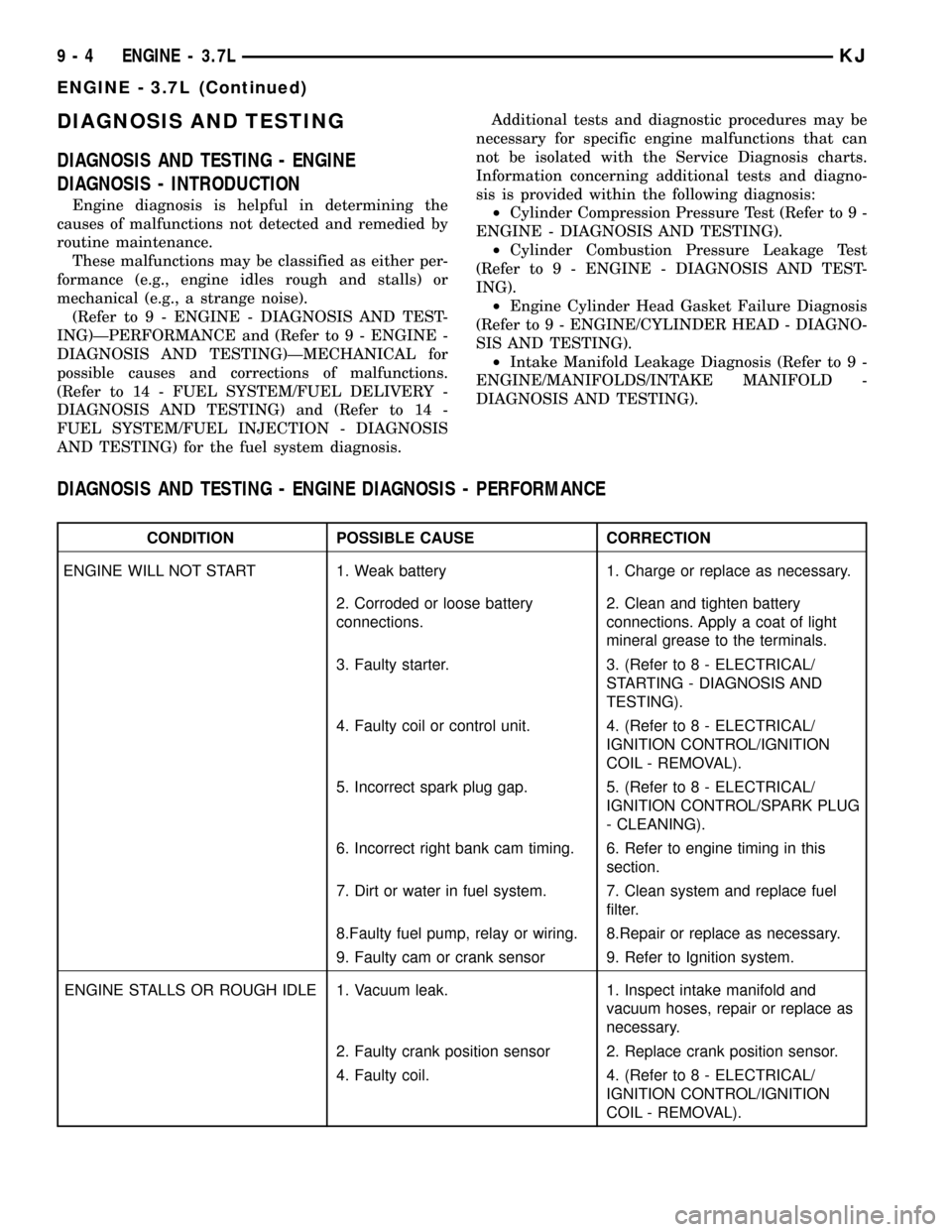
DIAGNOSIS AND TESTING - ENGINE DIAGNOSIS - PERFORMANCE
CONDITION POSSIBLE CAUSE CORRECTION
ENGINE WILL NOT START 1. Weak battery 1. Charge or replace as necessary.
2. Corroded or loose battery
connections.2. Clean and tighten battery
connections. Apply a coat of light
mineral grease to the terminals.
3. Faulty starter. 3. (Refer to 8 - ELECTRICAL/
STARTING - DIAGNOSIS AND
TESTING).
4. Faulty coil or control unit. 4. (Refer to 8 - ELECTRICAL/
IGNITION CONTROL/IGNITION
COIL - REMOVAL).
5. Incorrect spark plug gap. 5. (Refer to 8 - ELECTRICAL/
IGNITION CONTROL/SPARK PLUG
- CLEANING).
6. Incorrect right bank cam timing. 6. Refer to engine timing in this
section.
7. Dirt or water in fuel system. 7. Clean system and replace fuel
filter.
8.Faulty fuel pump, relay or wiring. 8.Repair or replace as necessary.
9. Faulty cam or crank sensor 9. Refer to Ignition system.
ENGINE STALLS OR ROUGH IDLE 1. Vacuum leak. 1. Inspect intake manifold and
vacuum hoses, repair or replace as
necessary.
2. Faulty crank position sensor 2. Replace crank position sensor.
4. Faulty coil. 4. (Refer to 8 - ELECTRICAL/
IGNITION CONTROL/IGNITION
COIL - REMOVAL).
9 - 4 ENGINE - 3.7LKJ
ENGINE - 3.7L (Continued)
Page 1223 of 1803
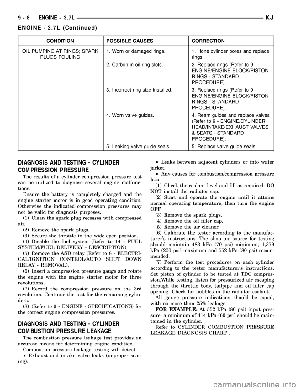
CONDITION POSSIBLE CAUSES CORRECTION
OIL PUMPING AT RINGS; SPARK
PLUGS FOULING1. Worn or damaged rings. 1. Hone cylinder bores and replace
rings.
2. Carbon in oil ring slots. 2. Replace rings (Refer to 9 -
ENGINE/ENGINE BLOCK/PISTON
RINGS - STANDARD
PROCEDURE).
3. Incorrect ring size installed. 3. Replace rings (Refer to 9 -
ENGINE/ENGINE BLOCK/PISTON
RINGS - STANDARD
PROCEDURE).
4. Worn valve guides. 4. Ream guides and replace valves
(Refer to 9 - ENGINE/CYLINDER
HEAD/INTAKE/EXHAUST VALVES
& SEATS - STANDARD
PROCEDURE).
5. Leaking valve guide seals. 5. Replace valve guide seals.
DIAGNOSIS AND TESTING - CYLINDER
COMPRESSION PRESSURE
The results of a cylinder compression pressure test
can be utilized to diagnose several engine malfunc-
tions.
Ensure the battery is completely charged and the
engine starter motor is in good operating condition.
Otherwise the indicated compression pressures may
not be valid for diagnosis purposes.
(1) Clean the spark plug recesses with compressed
air.
(2) Remove the spark plugs.
(3) Secure the throttle in the wide-open position.
(4) Disable the fuel system (Refer to 14 - FUEL
SYSTEM/FUEL DELIVERY - DESCRIPTION).
(5) Remove the ASD relay (Refer to 8 - ELECTRI-
CAL/IGNITION CONTROL/AUTO SHUT DOWN
RELAY - REMOVAL).
(6) Insert a compression pressure gauge and rotate
the engine with the engine starter motor for three
revolutions.
(7) Record the compression pressure on the 3rd
revolution. Continue the test for the remaining cylin-
ders.
(8) (Refer to 9 - ENGINE - SPECIFICATIONS) for
the correct engine compression pressures.
DIAGNOSIS AND TESTING - CYLINDER
COMBUSTION PRESSURE LEAKAGE
The combustion pressure leakage test provides an
accurate means for determining engine condition.
Combustion pressure leakage testing will detect:
²Exhaust and intake valve leaks (improper seat-
ing).²Leaks between adjacent cylinders or into water
jacket.
²Any causes for combustion/compression pressure
loss.
(1) Check the coolant level and fill as required. DO
NOT install the radiator cap.
(2) Start and operate the engine until it attains
normal operating temperature, then turn the engine
OFF.
(3) Remove the spark plugs.
(4) Remove the oil filler cap.
(5) Remove the air cleaner.
(6) Calibrate the tester according to the manufac-
turer's instructions. The shop air source for testing
should maintain 483 kPa (70 psi) minimum, 1,379
kPa (200 psi) maximum and 552 kPa (80 psi) recom-
mended.
(7) Perform the test procedures on each cylinder
according to the tester manufacturer's instructions.
Set piston of cylinder to be tested at TDC compres-
sion,While testing, listen for pressurized air escaping
through the throttle body, tailpipe and oil filler cap
opening. Check for bubbles in the radiator coolant.
All gauge pressure indications should be equal,
with no more than 25% leakage.
FOR EXAMPLE:At 552 kPa (80 psi) input pres-
sure, a minimum of 414 kPa (60 psi) should be main-
tained in the cylinder.
Refer to CYLINDER COMBUSTION PRESSURE
LEAKAGE DIAGNOSIS CHART .
9 - 8 ENGINE - 3.7LKJ
ENGINE - 3.7L (Continued)
Page 1226 of 1803
NOTE: Recheck bolt torque for engine lift plate
before removing engine.
(30) Secure the left and right engine wiring har-
nesses away from engine.
(31) Raise vehicle.
(32) Disconnect oxygen sensor wiring.
(33) Disconnect crankshaft postion sensor.
(34) Disconnect the engine block heater power
cable, if equipped.
(35) Disconnect the front propshaft at the front
differential and secure out of way.
NOTE: It is necessary to disconnect the front prop-
shaft for access to the starter and left side exhaust
flange.
(36) Remove the starter.
(37) Remove the ground straps from the left and
right side of the block.
(38) Disconnect the right and left exhaust pipes at
the manifolds and from the crossover, and remove
from the vehicle.
NOTE: The exhaust clamps at the manifolds cannot
be reused. New clamps must be used or leaks may
occur.
NOTE: For manual transmission vehicles, the trans-
mission must be removed from the vehicle, before
the engine can be removed. The manual transmis-
sion will contact the floorpan before the engine
clears the motor mounts, so it must be removed.
(39) Remove the structural cover.
(40) Remove torque convertor bolts, and mark
location for reassembly.
(41) Remove transmission bellhousing to engine
bolts.
(42) Loosen left and right engine mount thru bolts.
NOTE: It is not necessary to completely remove
engine mount thru bolts, for engine removal.
(43) Lower the vehicle.
(44) Support the transmission with a suitable jack.
(45) Connect a suitable engine hoist to the engine
lift plate.
(46) Remove engine from vehicle.
INSTALLATION
(1) Position the engine in the vehicle.
(2) Install both left and right side engine mounts
onto engine.
(3) Raise the vehicle.(4) Install the transmission bellhousing to engine
mounting bolts. Tighten the bolts to 41 N´m (30ft.
lbs.).
(5) Tighten the engine mount thru bolts.
(6) Install the torque convertor bolts.
(7) Connect the ground straps on the left and right
side of the engine.
(8) Install the starter.
(9) Connect the crankshaft position sensor.
(10) Install the engine block heater power cable, if
equipped.
CAUTION: The structural cover requires a specific
torque sequence. Failure to follow this sequence
may cause severe damage to the cover.
(11) Install the structural cover.
NOTE: New clamps must be used on exhaust man-
ifold flanges. Failure to use new clamps may result
in exhaust leaks.
(12) Install the left and right exhaust pipes.
(13) Connect the left and right oxygen sensors.
(14) Lower vehicle.
(15) Remove the engine lift plate.
(16) Connect the knock sensors.
(17) Connect the engine to body ground straps at
the left side of the cowl.
(18) Install the intake manifold.
(19) Install the engine oil dipstick tube.
(20) Install the power brake booster vacuum hose.
(21) Install the breather hoses.
(22) Install the PCV hose.
(23) Install the fuel rail.
(24) Install the coil over plugs.
(25) Connect the engine wiring harness at the fol-
lowing points:
²Intake air temperature (IAT) sensor
²Fuel Injectors
²Throttle Position (TPS) Switch
²Idle Air Control (IAC) Motor
²Engine Oil Pressure Switch
²Engine Coolant Temperature (ECT) Sensor
²Manifold Absolute Pressure MAP) Sensor
²Camshaft Position (CMP) Sensor
²Coil Over Plugs
²Crankshaft Position Sensor
(26) Connect lower radiator hose.
(27) Connect upper radiator hose.
(28) Connect throttle and speed control cables.
(29) Install the heater hose assembly.
(30) Install coolant recovery bottle.
(31) Install the power steering pump.
(32) Install the generator.
(33) Install the A/C compressor.
(34) Install the drive belt.
KJENGINE - 3.7L 9 - 11
ENGINE - 3.7L (Continued)
Page 1252 of 1803
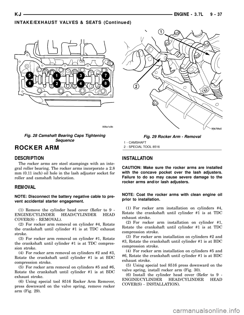
ROCKER ARM
DESCRIPTION
The rocker arms are steel stampings with an inte-
gral roller bearing. The rocker arms incorporate a 2.8
mm (0.11 inch) oil hole in the lash adjuster socket for
roller and camshaft lubrication.
REMOVAL
NOTE: Disconnect the battery negative cable to pre-
vent accidental starter engagement.
(1) Remove the cylinder head cover (Refer to 9 -
ENGINE/CYLINDER HEAD/CYLINDER HEAD
COVER(S) - REMOVAL).
(2) For rocker arm removal on cylinder #4, Rotate
the crankshaft until cylinder #1 is at TDC exhaust
stroke.
(3) For rocker arm removal on cylinder #1, Rotate
the crankshaft until cylinder #1 is at TDC compres-
sion stroke.
(4) For rocker arm removal on cylinders #2 and #3,
Rotate the crankshaft until cylinder #1 is at BDC
compression stroke.
(5) For rocker arm removal on cylinders #5 and #6,
Rotate the crankshaft until cylinder #1 is at BDC
exhaust stroke.
(6) Using special tool 8516 Rocker Arm Remover,
press downward on the valve spring, remove rocker
arm (Fig. 29).
INSTALLATION
CAUTION: Make sure the rocker arms are installed
with the concave pocket over the lash adjusters.
Failure to do so may cause severe damage to the
rocker arms and/or lash adjusters.
NOTE: Coat the rocker arms with clean engine oil
prior to installation.
(1) For rocker arm installation on cylinders #4,
Rotate the crankshaft until cylinder #1 is at TDC
exhaust stroke.
(2) For rocker arm installation on cylinder #1,
Rotate the crankshaft until cylinder #1 is at TDC
compression stroke.
(3) For rocker arm installation on cylinders #2 and
#3, Rotate the crankshaft until cylinder #1 is at BDC
compression stroke.
(4) For rocker arm installation on cylinders #5 and
#6, Rotate the crankshaft until cylinder #1 is at BDC
exhaust stroke.
(5) Using special tool 8516 press downward on the
valve spring, install rocker arm (Fig. 30).
(6) Install the cylinder head cover (Refer to 9 -
ENGINE/CYLINDER HEAD/CYLINDER HEAD
COVER(S) - INSTALLATION).
Fig. 28 Camshaft Bearing Caps Tightening
SequenceFig. 29 Rocker Arm - Removal
1 - CAMSHAFT
2 - SPECIAL TOOL 8516
KJENGINE - 3.7L 9 - 37
INTAKE/EXHAUST VALVES & SEATS (Continued)
Page 1294 of 1803
CAUTION: Care should be taken not to damage
camshaft target wheel. Do not hold target wheel
while loosening or tightening camshaft sprocket.
Do not place the target wheel near a magnetic
source of any kind. A damaged or magnetized tar-
get wheel could cause a vehicle no start condition.
CAUTION: Do not forcefully rotate the camshafts or
crankshaft independently of each other. Damaging
intake valve to piston contact will occur. Ensure
negative battery cable is disconnected to guard
against accidental starter engagement.
(13) Remove left and right camshaft sprocket bolts.
(14) While holding the left camshaft steel tube
with Special Tool 8428 Camshaft Wrench, remove the
left camshaft sprocket. Slowly rotate the camshaft
approximately 5 degrees clockwise to a neutral posi-
tion.
(15) While holding the right camshaft steel tube
with Special Tool 8428 Camshaft Wrench, remove the
right camshaft sprocket.
(16) Remove idler sprocket assembly bolt.
(17) Slide the idler sprocket assembly and crank
sprocket forward simultaneously to remove the pri-
mary and secondary chains.
(18) Remove both pivoting tensioner arms and
chain guides.
(19) Remove chain tensioner.
INSPECTION
Inspect the following components:
²Sprockets for excessive tooth wear. Some tooth
markings are normal and not a cause for sprocket
replacement.
²Idler sprocket assembly bushing and shaft for
excessive wear.
²Idler sprocket assembly spline joint. The joint
should be tight with no backlash or axial movement.
²Chain guides and tensioner arms. Replace these
parts if grooving in plastic face is more than 1 mm
(0.039 in.) deep. If plastic face is severely grooved or
melted, the tensioner lube jet may be clogged. The
tensioner should be replaced.
²Secondary chain tensioner piston and ratcheting
device. Inspect for evidence of heavy contact between
tensioner piston and tensioner arm. If this condition
exist the tensioner tensioner arm and chain should
be replaced.
²Primary chain tensioner plastic faces. Replace as
required.
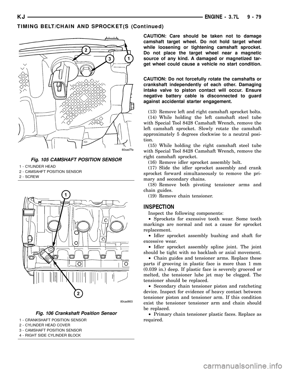
Fig. 105 CAMSHAFT POSITION SENSOR
1 - CYLINDER HEAD
2 - CAMSAHFT POSITION SENSOR
2 - SCREW
Fig. 106 Crankshaft Position Sensor
1 - CRANKSHAFT POSITION SENSOR
2 - CYLINDER HEAD COVER
3 - CAMSHAFT POSITION SENSOR
4 - RIGHT SIDE CYLINDER BLOCK
KJENGINE - 3.7L 9 - 79
TIMING BELT/CHAIN AND SPROCKET(S (Continued)
Page 1300 of 1803
ENGINE - 2.4L
DESCRIPTION
The 2.4 Liter (148 cu. in.) in-line four cylinder
engine is a double over head camshaft with hydraulic
lifters and four valve per cylinder design. The engine
is free-wheeling; meaning it has provisions for piston-
to-valve clearance. However valve-to-valve interference
can occur, if camshafts are rotated independently.
The cylinders are numbered from front of the
engine to the rear. The firing order is 1±3±4±2.
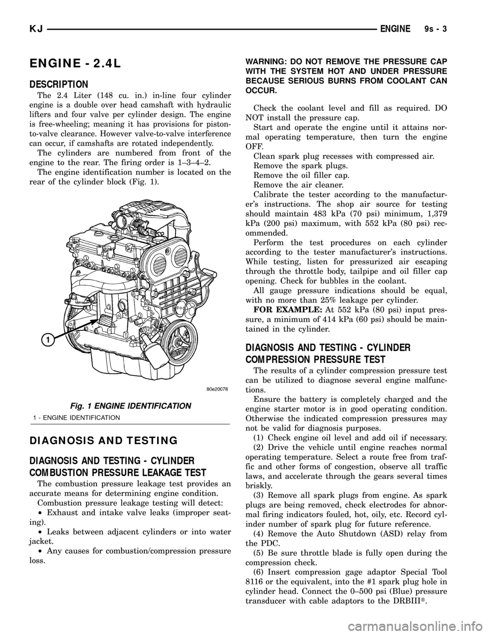
The engine identification number is located on the
rear of the cylinder block (Fig. 1).
DIAGNOSIS AND TESTING
DIAGNOSIS AND TESTING - CYLINDER
COMBUSTION PRESSURE LEAKAGE TEST
The combustion pressure leakage test provides an
accurate means for determining engine condition.
Combustion pressure leakage testing will detect:
²Exhaust and intake valve leaks (improper seat-
ing).
²Leaks between adjacent cylinders or into water
jacket.
²Any causes for combustion/compression pressure
loss.WARNING: DO NOT REMOVE THE PRESSURE CAP
WITH THE SYSTEM HOT AND UNDER PRESSURE
BECAUSE SERIOUS BURNS FROM COOLANT CAN
OCCUR.
Check the coolant level and fill as required. DO
NOT install the pressure cap.
Start and operate the engine until it attains nor-
mal operating temperature, then turn the engine
OFF.
Clean spark plug recesses with compressed air.
Remove the spark plugs.
Remove the oil filler cap.
Remove the air cleaner.
Calibrate the tester according to the manufactur-
er's instructions. The shop air source for testing
should maintain 483 kPa (70 psi) minimum, 1,379
kPa (200 psi) maximum, with 552 kPa (80 psi) rec-
ommended.
Perform the test procedures on each cylinder
according to the tester manufacturer's instructions.
While testing, listen for pressurized air escaping
through the throttle body, tailpipe and oil filler cap
opening. Check for bubbles in the coolant.
All gauge pressure indications should be equal,
with no more than 25% leakage per cylinder.
FOR EXAMPLE:At 552 kPa (80 psi) input pres-
sure, a minimum of 414 kPa (60 psi) should be main-
tained in the cylinder.
DIAGNOSIS AND TESTING - CYLINDER
COMPRESSION PRESSURE TEST
The results of a cylinder compression pressure test
can be utilized to diagnose several engine malfunc-
tions.
Ensure the battery is completely charged and the
engine starter motor is in good operating condition.
Otherwise the indicated compression pressures may
not be valid for diagnosis purposes.
(1) Check engine oil level and add oil if necessary.
(2) Drive the vehicle until engine reaches normal
operating temperature. Select a route free from traf-
fic and other forms of congestion, observe all traffic
laws, and accelerate through the gears several times
briskly.
(3) Remove all spark plugs from engine. As spark
plugs are being removed, check electrodes for abnor-
mal firing indicators fouled, hot, oily, etc. Record cyl-
inder number of spark plug for future reference.
(4) Remove the Auto Shutdown (ASD) relay from
the PDC.
(5) Be sure throttle blade is fully open during the
compression check.
(6) Insert compression gage adaptor Special Tool
8116 or the equivalent, into the #1 spark plug hole in
cylinder head. Connect the 0±500 psi (Blue) pressure
transducer with cable adaptors to the DRBIIIt.
Fig. 1 ENGINE IDENTIFICATION
1 - ENGINE IDENTIFICATION
KJENGINE9s-3