2002 JEEP LIBERTY Starter
[x] Cancel search: StarterPage 1302 of 1803
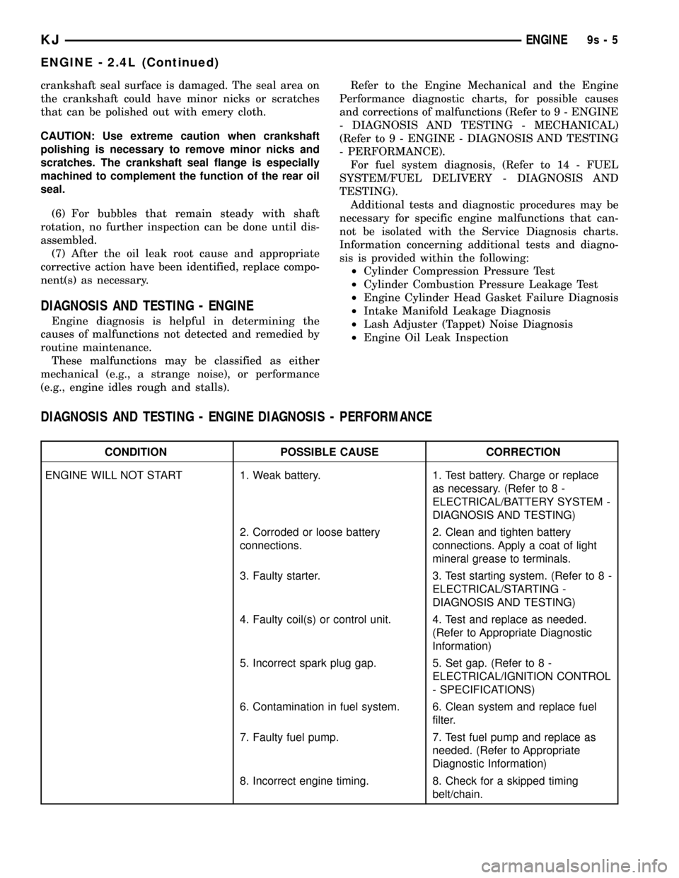
crankshaft seal surface is damaged. The seal area on
the crankshaft could have minor nicks or scratches
that can be polished out with emery cloth.
CAUTION: Use extreme caution when crankshaft
polishing is necessary to remove minor nicks and
scratches. The crankshaft seal flange is especially
machined to complement the function of the rear oil
seal.
(6) For bubbles that remain steady with shaft
rotation, no further inspection can be done until dis-
assembled.
(7) After the oil leak root cause and appropriate
corrective action have been identified, replace compo-
nent(s) as necessary.
DIAGNOSIS AND TESTING - ENGINE
Engine diagnosis is helpful in determining the
causes of malfunctions not detected and remedied by
routine maintenance.
These malfunctions may be classified as either
mechanical (e.g., a strange noise), or performance
(e.g., engine idles rough and stalls).Refer to the Engine Mechanical and the Engine
Performance diagnostic charts, for possible causes
and corrections of malfunctions (Refer to 9 - ENGINE
- DIAGNOSIS AND TESTING - MECHANICAL)
(Refer to 9 - ENGINE - DIAGNOSIS AND TESTING
- PERFORMANCE).
For fuel system diagnosis, (Refer to 14 - FUEL
SYSTEM/FUEL DELIVERY - DIAGNOSIS AND
TESTING).
Additional tests and diagnostic procedures may be
necessary for specific engine malfunctions that can-
not be isolated with the Service Diagnosis charts.
Information concerning additional tests and diagno-
sis is provided within the following:
²Cylinder Compression Pressure Test
²Cylinder Combustion Pressure Leakage Test
²Engine Cylinder Head Gasket Failure Diagnosis
²Intake Manifold Leakage Diagnosis
²Lash Adjuster (Tappet) Noise Diagnosis
²Engine Oil Leak Inspection
DIAGNOSIS AND TESTING - ENGINE DIAGNOSIS - PERFORMANCE
CONDITION POSSIBLE CAUSE CORRECTION
ENGINE WILL NOT START 1. Weak battery. 1. Test battery. Charge or replace
as necessary. (Refer to 8 -
ELECTRICAL/BATTERY SYSTEM -
DIAGNOSIS AND TESTING)
2. Corroded or loose battery
connections.2. Clean and tighten battery
connections. Apply a coat of light
mineral grease to terminals.
3. Faulty starter. 3. Test starting system. (Refer to 8 -
ELECTRICAL/STARTING -
DIAGNOSIS AND TESTING)
4. Faulty coil(s) or control unit. 4. Test and replace as needed.
(Refer to Appropriate Diagnostic
Information)
5. Incorrect spark plug gap. 5. Set gap. (Refer to 8 -
ELECTRICAL/IGNITION CONTROL
- SPECIFICATIONS)
6. Contamination in fuel system. 6. Clean system and replace fuel
filter.
7. Faulty fuel pump. 7. Test fuel pump and replace as
needed. (Refer to Appropriate
Diagnostic Information)
8. Incorrect engine timing. 8. Check for a skipped timing
belt/chain.
KJENGINE9s-5
ENGINE - 2.4L (Continued)
Page 1306 of 1803
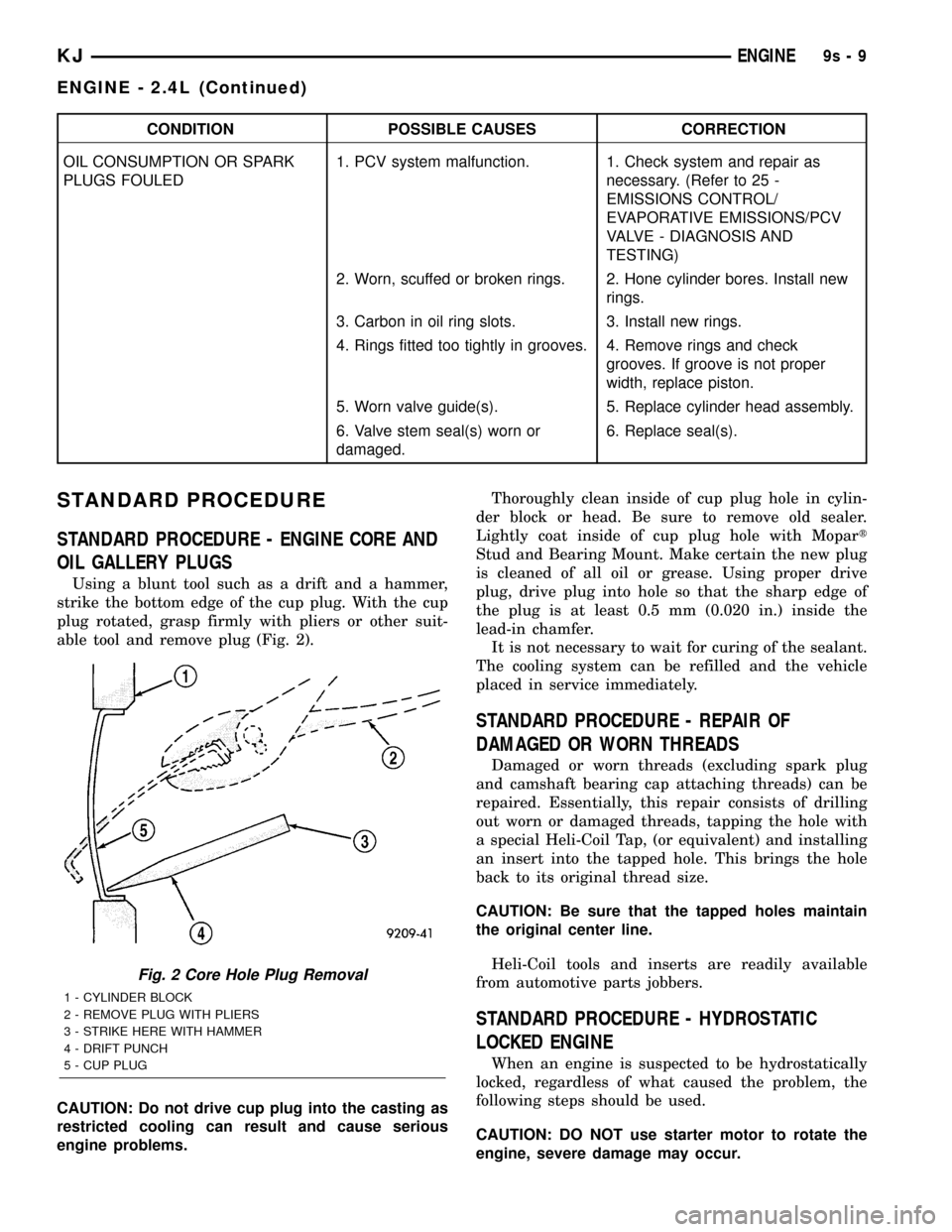
CONDITION POSSIBLE CAUSES CORRECTION
OIL CONSUMPTION OR SPARK
PLUGS FOULED1. PCV system malfunction. 1. Check system and repair as
necessary. (Refer to 25 -
EMISSIONS CONTROL/
EVAPORATIVE EMISSIONS/PCV
VALVE - DIAGNOSIS AND
TESTING)
2. Worn, scuffed or broken rings. 2. Hone cylinder bores. Install new
rings.
3. Carbon in oil ring slots. 3. Install new rings.
4. Rings fitted too tightly in grooves. 4. Remove rings and check
grooves. If groove is not proper
width, replace piston.
5. Worn valve guide(s). 5. Replace cylinder head assembly.
6. Valve stem seal(s) worn or
damaged.6. Replace seal(s).
STANDARD PROCEDURE
STANDARD PROCEDURE - ENGINE CORE AND
OIL GALLERY PLUGS
Using a blunt tool such as a drift and a hammer,
strike the bottom edge of the cup plug. With the cup
plug rotated, grasp firmly with pliers or other suit-
able tool and remove plug (Fig. 2).
CAUTION: Do not drive cup plug into the casting as
restricted cooling can result and cause serious
engine problems.Thoroughly clean inside of cup plug hole in cylin-
der block or head. Be sure to remove old sealer.
Lightly coat inside of cup plug hole with Mopart
Stud and Bearing Mount. Make certain the new plug
is cleaned of all oil or grease. Using proper drive
plug, drive plug into hole so that the sharp edge of
the plug is at least 0.5 mm (0.020 in.) inside the
lead-in chamfer.
It is not necessary to wait for curing of the sealant.
The cooling system can be refilled and the vehicle
placed in service immediately.
STANDARD PROCEDURE - REPAIR OF
DAMAGED OR WORN THREADS
Damaged or worn threads (excluding spark plug
and camshaft bearing cap attaching threads) can be
repaired. Essentially, this repair consists of drilling
out worn or damaged threads, tapping the hole with
a special Heli-Coil Tap, (or equivalent) and installing
an insert into the tapped hole. This brings the hole
back to its original thread size.
CAUTION: Be sure that the tapped holes maintain
the original center line.
Heli-Coil tools and inserts are readily available
from automotive parts jobbers.
STANDARD PROCEDURE - HYDROSTATIC
LOCKED ENGINE
When an engine is suspected to be hydrostatically
locked, regardless of what caused the problem, the
following steps should be used.
CAUTION: DO NOT use starter motor to rotate the
engine, severe damage may occur.
Fig. 2 Core Hole Plug Removal
1 - CYLINDER BLOCK
2 - REMOVE PLUG WITH PLIERS
3 - STRIKE HERE WITH HAMMER
4 - DRIFT PUNCH
5 - CUP PLUG
KJENGINE9s-9
ENGINE - 2.4L (Continued)
Page 1309 of 1803

NOTE: Plastigage is available in a variety of clear-
ance ranges. Use the most appropriate range for
the specifications you are checking.
(4) Install the proper crankshaft bearings to
achieve the specified bearing clearances. (Refer to 9 -
ENGINE/ENGINE BLOCK/CRANKSHAFT MAIN
BEARINGS - STANDARD PROCEDURE) (Refer to 9
- ENGINE/ENGINE BLOCK/CONNECTING ROD
BEARINGS - STANDARD PROCEDURE)
REMOVAL - ENGINE ASSEMBLY
(1) Disconnect the battery negative cable.
(2) Remove hood. Mark hood hinge location for
reinstallation.
(3) Remove air cleaner assembly.
(4) Remove radiator core support bracket.
(5) Remove fan shroud with electric fan assembly.
(6) Remove drive belt.
NOTE: It is NOT necessary to discharge the A/C
system to remove the engine.
(7) Remove A/C compressor and secure away from
engine with lines attached.
(8) Remove generator and secure away from
engine.
NOTE: Do NOT remove the phenolic pulley from the
P/S pump. It is not required for P/S pump removal.
(9) Remove power steering pump with lines
attached and secure away from engine.
(10) Drain cooling system.
(11) Remove coolant bottle.
(12) Disconnect the heater hoses from the engine.
(13) Disconnect heater hoses from heater core and
remove hose assembly.
(14) Disconnect throttle and speed control cables.
(15) Remove upper radiator hose from engine.
(16) Remove lower radiator hose from engine.
(17) Disconnect the engine to body ground straps
at the left side of cowl.
(18) Disconnect the engine wiring harness at the
following points:
²Intake air temperature (IAT) sensor
²Fuel Injectors
²Throttle Position (TPS) Switch
²Idle Air Control (IAC) Motor
²Engine Oil Pressure Switch
²Engine Coolant Temperature (ECT) Sensor
²Manifold Absolute Pressure MAP) Sensor
²Camshaft Position (CMP) Sensor
²Coil Over Plugs
²Crankshaft Position Sensor
(19) Remove coil over plugs.
(20) Release fuel rail pressure.(21) Remove fuel rail and secure away from
engine.
(22) Remove the PCV hose.
(23) Remove the breather hoses.
(24) Remove the vacuum hose for the power brake
booster.
(25) Disconnect knock sensors.
(26) Secure the left and right engine wiring har-
nesses away from engine.
(27) Raise vehicle.
(28) Disconnect oxygen sensor wiring.
(29) Disconnect crankshaft postion sensor.
(30) Disconnect the engine block heater power
cable, if equipped.
(31) Disconnect the front propshaft at the front
differential and secure out of way.
(32) Remove the starter.
(33) Remove the ground straps from the engine
(34) Disconnect the exhaust pipes at the manifold.
(35) Remove the structural cover, if equipped.
(36) Remove torque convertor bolts, and mark
location for reassembly.
(37) Remove transmission bellhousing to engine
bolts.
(38) Loosen left and right engine mount thru bolts.
NOTE: It is not necessary to completely remove
engine mount thru bolts, for engine removal.
(39) Lower the vehicle.
(40) Support the transmission with a suitable jack.
(41) Connect a suitable engine hoist to the engine.
CAUTION: The 2.4L engine with manual transmis-
sions, can be removed without removing the man-
ual transmission. Use caution when attempting this
procedure as the clearance is tight.
(42) Remove engine from vehicle.
INSTALLATION - ENGINE ASSEMBLY
(1) Position the engine in the vehicle.
CAUTION: Use caution when installing 2.4L engine
into vehicle equipped with manual transmission, as
clearance is tight.
(2) Install both left and right side engine mounts
into the frame mounts.
(3) Raise the vehicle.
(4) Install the transmission bellhousing to engine
mounting bolts. Tighten the bolts to 41 N´m (30ft.
lbs.).
(5) Tighten the engine mount thru bolts.
(6) Install the torque convertor bolts.
(7) Connect the ground straps on the left and right
side of the engine.
9s - 12 ENGINEKJ
ENGINE - 2.4L (Continued)
Page 1310 of 1803
(8) Install the starter.
(9) Connect the crankshaft position sensor.
(10) Install the engine block heater power cable, if
equipped.
CAUTION: The structural cover requires a specific
torque sequence. Failure to follow this sequence
may cause severe damage to the cover.
(11) Install the structural cover.
(12) Install the exhaust pipe.
(13) Connect the oxygen sensors.
(14) Lower vehicle.
(15) Connect the knock sensors.
(16) Connect the engine to body ground straps.
(17) Install the power brake booster vacuum hose.
(18) Install the breather hoses.
(19) Install the PCV hose.
(20) Install the fuel rail.
(21) Install the coil over plugs.
(22) Reconnect the engine wiring harness at the
following points:
²Intake air temperature (IAT) sensor
²Fuel Injectors
²Throttle Position (TPS) Switch
²Idle Air Control (IAC) Motor
²Engine Oil Pressure Switch
²Engine Coolant Temperature (ECT) Sensor
²Manifold Absolute Pressure MAP) Sensor
²Camshaft Position (CMP) Sensor
²Coil Over Plugs
²Crankshaft Position Sensor
(23) Connect lower radiator hose.
(24) Connect upper radiator hose.
(25) Connect throttle and speed control cables.
(26) Install the heater hose assembly.
(27) Install coolant recovery bottle.
(28) Install the power steering pump.
(29) Install the generator.
(30) Install the A/C compressor.
(31) Install the drive belt.
(32) Install the fan shroud with the electric fan
assembly.
(33) Install the radiator core support bracket.
(34) Install the air cleaner assembly.
(35) Refill the engine cooling system.
(36) Install the hood.
(37) Check and fill engine oil.
(38) Connect the battery negative cable.
(39) Start the engine and check for leaks.SPECIFICATIONS
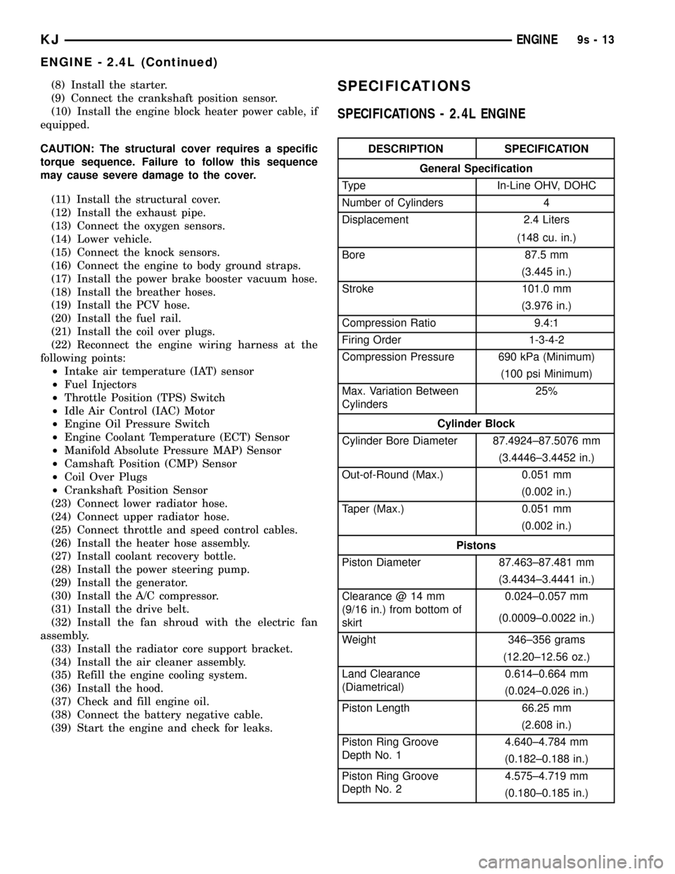
SPECIFICATIONS - 2.4L ENGINE
DESCRIPTION SPECIFICATION
General Specification
Type In-Line OHV, DOHC
Number of Cylinders 4
Displacement 2.4 Liters
(148 cu. in.)
Bore 87.5 mm
(3.445 in.)
Stroke 101.0 mm
(3.976 in.)
Compression Ratio 9.4:1
Firing Order 1-3-4-2
Compression Pressure 690 kPa (Minimum)
(100 psi Minimum)
Max. Variation Between
Cylinders25%
Cylinder Block
Cylinder Bore Diameter 87.4924±87.5076 mm
(3.4446±3.4452 in.)
Out-of-Round (Max.) 0.051 mm
(0.002 in.)
Taper (Max.) 0.051 mm
(0.002 in.)
Pistons
Piston Diameter 87.463±87.481 mm
(3.4434±3.4441 in.)
Clearance @ 14 mm
(9/16 in.) from bottom of
skirt0.024±0.057 mm
(0.0009±0.0022 in.)
Weight 346±356 grams
(12.20±12.56 oz.)
Land Clearance
(Diametrical)0.614±0.664 mm
(0.024±0.026 in.)
Piston Length 66.25 mm
(2.608 in.)
Piston Ring Groove
Depth No. 14.640±4.784 mm
(0.182±0.188 in.)
Piston Ring Groove
Depth No. 24.575±4.719 mm
(0.180±0.185 in.)
KJENGINE9s-13
ENGINE - 2.4L (Continued)
Page 1416 of 1803
REMOVAL
(1) Remove fuel rail. Refer to Fuel Injector Rail
Removal.
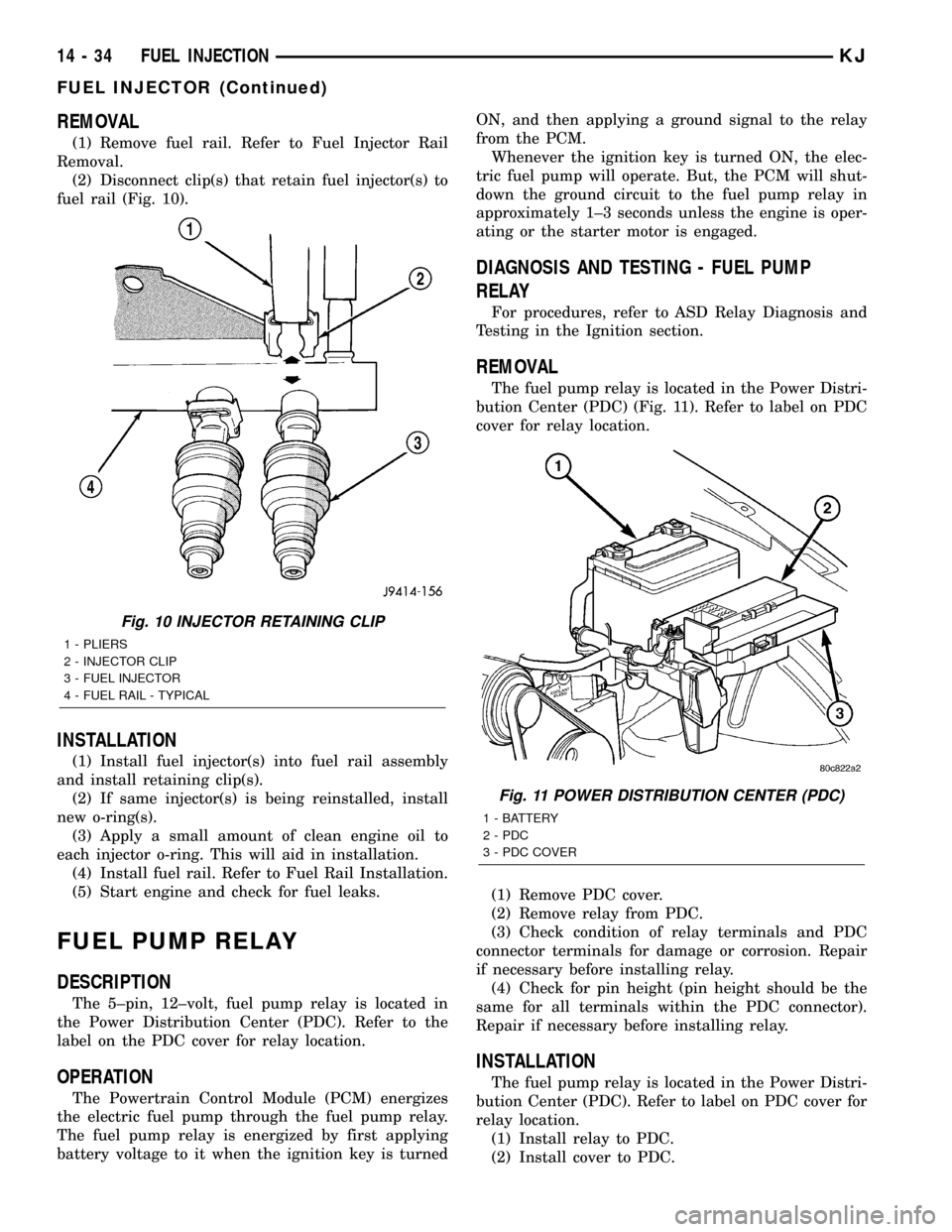
(2) Disconnect clip(s) that retain fuel injector(s) to
fuel rail (Fig. 10).
INSTALLATION
(1) Install fuel injector(s) into fuel rail assembly
and install retaining clip(s).
(2) If same injector(s) is being reinstalled, install
new o-ring(s).
(3) Apply a small amount of clean engine oil to
each injector o-ring. This will aid in installation.
(4) Install fuel rail. Refer to Fuel Rail Installation.
(5) Start engine and check for fuel leaks.
FUEL PUMP RELAY
DESCRIPTION
The 5±pin, 12±volt, fuel pump relay is located in
the Power Distribution Center (PDC). Refer to the
label on the PDC cover for relay location.
OPERATION
The Powertrain Control Module (PCM) energizes
the electric fuel pump through the fuel pump relay.
The fuel pump relay is energized by first applying
battery voltage to it when the ignition key is turnedON, and then applying a ground signal to the relay
from the PCM.
Whenever the ignition key is turned ON, the elec-
tric fuel pump will operate. But, the PCM will shut-
down the ground circuit to the fuel pump relay in
approximately 1±3 seconds unless the engine is oper-
ating or the starter motor is engaged.
DIAGNOSIS AND TESTING - FUEL PUMP
RELAY
For procedures, refer to ASD Relay Diagnosis and
Testing in the Ignition section.
REMOVAL
The fuel pump relay is located in the Power Distri-
bution Center (PDC) (Fig. 11). Refer to label on PDC
cover for relay location.
(1) Remove PDC cover.
(2) Remove relay from PDC.
(3) Check condition of relay terminals and PDC
connector terminals for damage or corrosion. Repair
if necessary before installing relay.
(4) Check for pin height (pin height should be the
same for all terminals within the PDC connector).
Repair if necessary before installing relay.
INSTALLATION
The fuel pump relay is located in the Power Distri-
bution Center (PDC). Refer to label on PDC cover for
relay location.
(1) Install relay to PDC.
(2) Install cover to PDC.
Fig. 10 INJECTOR RETAINING CLIP
1 - PLIERS
2 - INJECTOR CLIP
3 - FUEL INJECTOR
4 - FUEL RAIL - TYPICAL
Fig. 11 POWER DISTRIBUTION CENTER (PDC)
1 - BATTERY
2 - PDC
3 - PDC COVER
14 - 34 FUEL INJECTIONKJ
FUEL INJECTOR (Continued)
Page 1710 of 1803
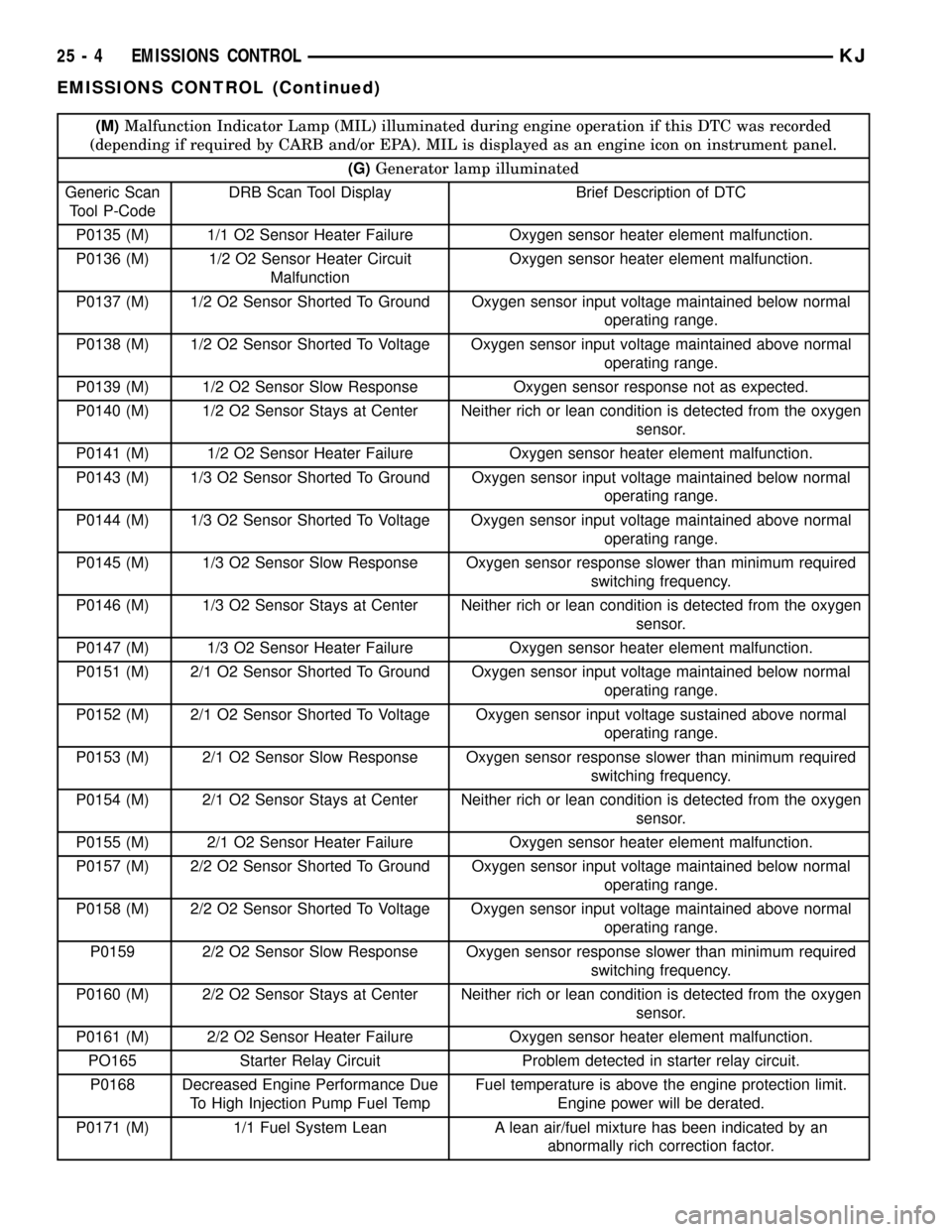
(M)Malfunction Indicator Lamp (MIL) illuminated during engine operation if this DTC was recorded
(depending if required by CARB and/or EPA). MIL is displayed as an engine icon on instrument panel.
(G)Generator lamp illuminated
Generic Scan
Tool P-CodeDRB Scan Tool Display Brief Description of DTC
P0135 (M) 1/1 O2 Sensor Heater Failure Oxygen sensor heater element malfunction.
P0136 (M) 1/2 O2 Sensor Heater Circuit
MalfunctionOxygen sensor heater element malfunction.
P0137 (M) 1/2 O2 Sensor Shorted To Ground Oxygen sensor input voltage maintained below normal
operating range.
P0138 (M) 1/2 O2 Sensor Shorted To Voltage Oxygen sensor input voltage maintained above normal
operating range.
P0139 (M) 1/2 O2 Sensor Slow Response Oxygen sensor response not as expected.
P0140 (M) 1/2 O2 Sensor Stays at Center Neither rich or lean condition is detected from the oxygen
sensor.
P0141 (M) 1/2 O2 Sensor Heater Failure Oxygen sensor heater element malfunction.
P0143 (M) 1/3 O2 Sensor Shorted To Ground Oxygen sensor input voltage maintained below normal
operating range.
P0144 (M) 1/3 O2 Sensor Shorted To Voltage Oxygen sensor input voltage maintained above normal
operating range.
P0145 (M) 1/3 O2 Sensor Slow Response Oxygen sensor response slower than minimum required
switching frequency.
P0146 (M) 1/3 O2 Sensor Stays at Center Neither rich or lean condition is detected from the oxygen
sensor.
P0147 (M) 1/3 O2 Sensor Heater Failure Oxygen sensor heater element malfunction.
P0151 (M) 2/1 O2 Sensor Shorted To Ground Oxygen sensor input voltage maintained below normal
operating range.
P0152 (M) 2/1 O2 Sensor Shorted To Voltage Oxygen sensor input voltage sustained above normal
operating range.
P0153 (M) 2/1 O2 Sensor Slow Response Oxygen sensor response slower than minimum required
switching frequency.
P0154 (M) 2/1 O2 Sensor Stays at Center Neither rich or lean condition is detected from the oxygen
sensor.
P0155 (M) 2/1 O2 Sensor Heater Failure Oxygen sensor heater element malfunction.
P0157 (M) 2/2 O2 Sensor Shorted To Ground Oxygen sensor input voltage maintained below normal
operating range.
P0158 (M) 2/2 O2 Sensor Shorted To Voltage Oxygen sensor input voltage maintained above normal
operating range.
P0159 2/2 O2 Sensor Slow Response Oxygen sensor response slower than minimum required
switching frequency.
P0160 (M) 2/2 O2 Sensor Stays at Center Neither rich or lean condition is detected from the oxygen
sensor.
P0161 (M) 2/2 O2 Sensor Heater Failure Oxygen sensor heater element malfunction.
PO165 Starter Relay Circuit Problem detected in starter relay circuit.
P0168 Decreased Engine Performance Due
To High Injection Pump Fuel TempFuel temperature is above the engine protection limit.
Engine power will be derated.
P0171 (M) 1/1 Fuel System Lean A lean air/fuel mixture has been indicated by an
abnormally rich correction factor.
25 - 4 EMISSIONS CONTROLKJ
EMISSIONS CONTROL (Continued)
Page 1715 of 1803
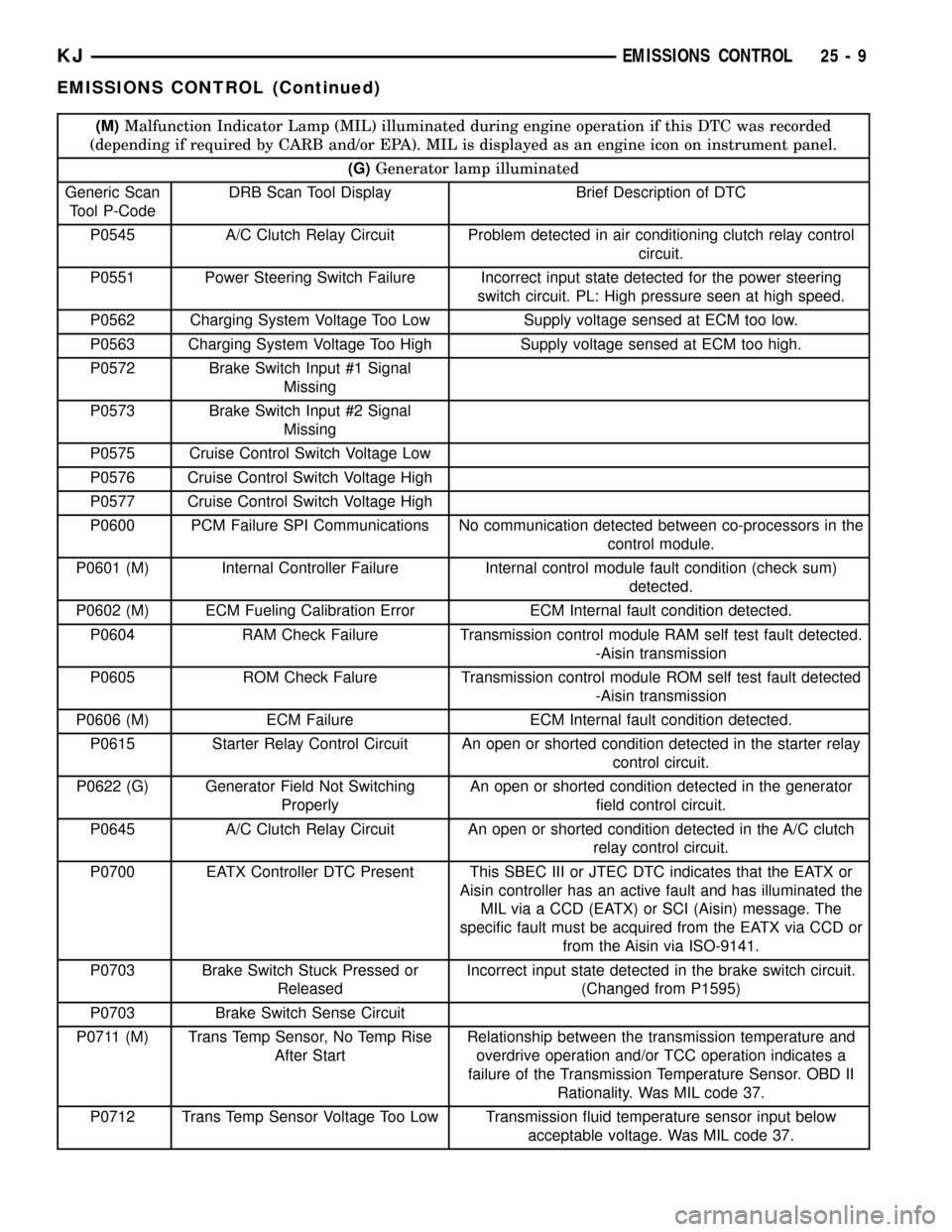
(M)Malfunction Indicator Lamp (MIL) illuminated during engine operation if this DTC was recorded
(depending if required by CARB and/or EPA). MIL is displayed as an engine icon on instrument panel.
(G)Generator lamp illuminated
Generic Scan
Tool P-CodeDRB Scan Tool Display Brief Description of DTC
P0545 A/C Clutch Relay Circuit Problem detected in air conditioning clutch relay control
circuit.
P0551 Power Steering Switch Failure Incorrect input state detected for the power steering
switch circuit. PL: High pressure seen at high speed.
P0562 Charging System Voltage Too Low Supply voltage sensed at ECM too low.
P0563 Charging System Voltage Too High Supply voltage sensed at ECM too high.
P0572 Brake Switch Input #1 Signal
Missing
P0573 Brake Switch Input #2 Signal
Missing
P0575 Cruise Control Switch Voltage Low
P0576 Cruise Control Switch Voltage High
P0577 Cruise Control Switch Voltage High
P0600 PCM Failure SPI Communications No communication detected between co-processors in the
control module.
P0601 (M) Internal Controller Failure Internal control module fault condition (check sum)
detected.
P0602 (M) ECM Fueling Calibration Error ECM Internal fault condition detected.
P0604 RAM Check Failure Transmission control module RAM self test fault detected.
-Aisin transmission
P0605 ROM Check Falure Transmission control module ROM self test fault detected
-Aisin transmission
P0606 (M) ECM Failure ECM Internal fault condition detected.
P0615 Starter Relay Control Circuit An open or shorted condition detected in the starter relay
control circuit.
P0622 (G) Generator Field Not Switching
ProperlyAn open or shorted condition detected in the generator
field control circuit.
P0645 A/C Clutch Relay Circuit An open or shorted condition detected in the A/C clutch
relay control circuit.
P0700 EATX Controller DTC Present This SBEC III or JTEC DTC indicates that the EATX or
Aisin controller has an active fault and has illuminated the
MIL via a CCD (EATX) or SCI (Aisin) message. The
specific fault must be acquired from the EATX via CCD or
from the Aisin via ISO-9141.
P0703 Brake Switch Stuck Pressed or
ReleasedIncorrect input state detected in the brake switch circuit.
(Changed from P1595)
P0703 Brake Switch Sense Circuit
P0711 (M) Trans Temp Sensor, No Temp Rise
After StartRelationship between the transmission temperature and
overdrive operation and/or TCC operation indicates a
failure of the Transmission Temperature Sensor. OBD II
Rationality. Was MIL code 37.
P0712 Trans Temp Sensor Voltage Too Low Transmission fluid temperature sensor input below
acceptable voltage. Was MIL code 37.
KJEMISSIONS CONTROL 25 - 9
EMISSIONS CONTROL (Continued)
Page 1750 of 1803

FUEL PRESSURE REGULATOR -
DESCRIPTION.......................14-13
FUEL PRESSURE REGULATOR -
INSTALLATION.......................14-14
FUEL PRESSURE REGULATOR -
OPERATION.........................14-14
FUEL PRESSURE REGULATOR -
REMOVAL..........................14-14
FUEL PUMP - DESCRIPTION............14-15
FUEL PUMP - OPERATION.............14-15
FUEL PUMP AMPERAGE TEST -
DIAGNOSIS AND TESTING.............14-16
FUEL PUMP CAPACITY TEST -
DIAGNOSIS AND TESTING.............14-15
FUEL PUMP MODULE - DESCRIPTION....14-18
FUEL PUMP MODULE - INSTALLATION . . . 14-19
FUEL PUMP MODULE - OPERATION......14-18
FUEL PUMP MODULE - REMOVAL.......14-18
FUEL PUMP PRESSURE TEST -
DIAGNOSIS AND TESTING.............14-15
FUEL PUMP RELAY - DESCRIPTION......14-34
FUEL PUMP RELAY - DIAGNOSIS AND
TESTING...........................14-34
FUEL PUMP RELAY - INSTALLATION.....14-34
FUEL PUMP RELAY - OPERATION........14-34
FUEL PUMP RELAY - REMOVAL.........14-34
FUEL PUMP RELAYS - DIAGNOSIS AND
TESTING, ASD........................8I-4
FUEL RAIL - DESCRIPTION.............14-21
FUEL RAIL - INSTALLATION..............14-24
FUEL RAIL - OPERATION...............14-21
FUEL RAIL - REMOVAL................14-22
FUEL SYSTEM PRESSURE RELEASE -
STANDARD PROCEDURE................14-4
FUEL SYSTEM PRESSURE,
SPECIFICATIONS......................14-5
FUEL SYSTEM, SPECIAL TOOLS..........14-6
FUEL TANK - DESCRIPTION............14-24
FUEL TANK - INSTALLATION............14-27
FUEL TANK - OPERATION..............14-24
FUEL TANK - REMOVAL...............14-25
FUEL TANK CHECK VALVE -
DESCRIPTION.......................14-28
FUEL TANK CHECK VALVE -
INSTALLATION.......................14-28
FUEL TANK CHECK VALVE - OPERATION . . 14-28
FUEL TANK CHECK VALVE - REMOVAL....14-28
FUEL TANK SKID PLATE - INSTALLATION . . . 13-9
FUEL TANK SKID PLATE - REMOVAL......13-9
FULL TIME INDICATOR - DESCRIPTION . . . 8J-29
FULL TIME INDICATOR - OPERATION.....8J-30
FUNCTION - DIAGNOSIS AND TESTING,
REAR HVAC CONTROL ASSEMBLY
WINDOW DEFOGGER..................8G-9
FUNCTIONS - DESCRIPTION, CIRCUIT . . 8W-01-6
FUSE - DESCRIPTION, IOD...........8W-97-3
FUSE - INSTALLATION, IOD..........8W-97-3
FUSE - OPERATION, IOD.............8W-97-3
FUSE - REMOVAL, IOD..............8W-97-3
FUSES POWERING SEVERAL LOADS -
STANDARD PROCEDURE, TESTING
FOR A SHORT TO GROUND ON.......8W-01-9
GALLERY PLUGS - STANDARD
PROCEDURE, ENGINE CORE AND OIL.....9-10
GAP AND FLUSH - SPECIFICATIONS.....23-116
GAS ENGINES - GENERATOR RATINGS....8F-23
GAS POWERED - STARTER MOTOR......8F-39
GAS POWERED - TORQUE
.............8F-38
GASKET - DIAGNOSIS AND TESTING,
CYLINDER HEAD
..................9-19,9-30
GASKET SURFACE PREPARATION -
STANDARD PROCEDURE, ENGINE
.........9-9
GATE - INSTALLATION, SWING
.........23-138
GATE - REMOVAL, SWING
............23-138
GATE AJAR INDICATOR - DESCRIPTION
. . . 8J-20
GATE AJAR INDICATOR - OPERATION
.....8J-20
GATE BELTLINE WEATHERSTRIP -
INSTALLATION, SWING
...............23-186
GATE BELTLINE WEATHERSTRIP -
REMOVAL, SWING
...................23-186
GATE OPENING WEATHERSTRIP -
INSTALLATION, SWING
...............23-186
GATE OPENING WEATHERSTRIP -
REMOVAL, SWING
...................23-186
GAUGE - DESCRIPTION, ENGINE
TEMPERATURE
......................8J-18
GAUGE - DESCRIPTION, FUEL
...........8J-19GAUGE - OPERATION, ENGINE
TEMPERATURE......................8J-18
GAUGE - OPERATION, FUEL............8J-20
GEAR - DESCRIPTION.................19-13
GEAR - INSTALLATION, PINION
GEAR/RING..........................3-46
GEAR - OPERATION...................19-13
GEAR - REMOVAL, PINION GEAR/RING....3-44
GEAR/RING GEAR - INSTALLATION,
PINION.............................3-46
GEAR/RING GEAR - REMOVAL, PINION....3-44
GEAR/RING GEAR/TONE RING -
INSTALLATION, PINION............3-112,3-82
GEAR/RING GEAR/TONE RING -
REMOVAL, PINION...............3-110,3-79
GEARSHIFT CABLE - ADJUSTMENTS....21-130
GEARSHIFT CABLE - DIAGNOSIS AND
TESTING..........................21-128
GEARSHIFT CABLE - INSTALLATION.....21-129
GEARSHIFT CABLE - REMOVAL........21-128
GEAR/TONE RING - INSTALLATION,
PINION GEAR/RING...............3-112,3-82
GEAR/TONE RING - REMOVAL, PINION
GEAR/RING.....................3-110,3-79
GEARTRAIN - ASSEMBLY, PLANETARY . . . 21-160
GEARTRAIN - CLEANING, PLANETARY . . . 21-159
GEARTRAIN - DESCRIPTION,
PLANETARY........................21-157
GEARTRAIN - DISASSEMBLY,
PLANETARY........................21-159
GEARTRAIN - INSPECTION, PLANETARY . 21-159
GEARTRAIN - OPERATION, PLANETARY . . 21-157
GENERAL - WARNINGS.............8W-01-7
GENERATOR - DESCRIPTION...........8F-25
GENERATOR - INSTALLATION...........8F-26
GENERATOR - OPERATION.............8F-25
GENERATOR - REMOVAL...............8F-25
GENERATOR DECOUPLER - DIAGNOSIS
AND TESTING.......................8F-27
GENERATOR DECOUPLER PULLEY -
DESCRIPTION.......................8F-26
GENERATOR DECOUPLER PULLEY -
INSTALLATION.......................8F-30
GENERATOR DECOUPLER PULLEY -
OPERATION.........................8F-27
GENERATOR DECOUPLER PULLEY -
REMOVAL..........................8F-27
GENERATOR RATINGS, GAS ENGINES....8F-23
GLASS - INSTALLATION, DOOR . . 23-122,23-129,
23-172
GLASS - INSTALLATION, FLIP-UP.......23-136
GLASS - REMOVAL, DOOR......23-122,23-129,
23-172
GLASS - REMOVAL, FLIP-UP..........23-136
GLASS AJAR INDICATOR - DESCRIPTION . . 8J-21
GLASS AJAR INDICATOR - OPERATION . . . 8J-21
GLASS AJAR SWITCH - DESCRIPTION,
FLIP-UP............................8L-77
GLASS AJAR SWITCH - OPERATION,
FLIP-UP............................8L-77
GLASS HEATING GRID REPAIR -
STANDARD PROCEDURE, REAR..........8G-4
GLASS LATCH - INSTALLATION, FLIP-UP . 23-136
GLASS LATCH - REMOVAL, FLIP-UP.....23-136
GLASS PANEL - INSTALLATION........23-178
GLASS PANEL - REMOVAL............23-178
GLASS PANEL ADJUSTMENT,
ADJUSTMENTS - SUNROOF...........23-178
GLASS PANEL SEAL - INSTALLATION
....23-178
GLASS PANEL SEAL - REMOVAL
.......23-178
GLASS RELEASE SWITCH - DIAGNOSIS
AND TESTING, FLIP-UP
................8N-5
GLASS RUN CHANNEL - INSTALLATION
. 23-123,
23-130
GLASS RUN CHANNEL - REMOVAL
.....23-123,
23-130
GLASS SUPPORT CYLINDER -
INSTALLATION, FLIP-UP
..............23-139
GLASS SUPPORT CYLINDER -
REMOVAL, FLIP-UP
..................23-139
GLOVE BOX - INSTALLATION
..........23-148
GLOVE BOX - REMOVAL
..............23-148
GLOVE BOX LATCH - INSTALLATION
....23-148
GLOVE BOX LATCH - REMOVAL
........23-148
GLOVE BOX LATCH STRIKER -
INSTALLATION
......................23-149
GLOVE BOX LATCH STRIKER - REMOVAL
. 23-148GRAB HANDLE - INSTALLATION,
A-PILLAR TRIM.....................23-156
GRAB HANDLE - REMOVAL, A-PILLAR
TRIM.............................23-156
GRID - DESCRIPTION, REAR WINDOW
DEFOGGER..........................8G-5
GRID - DIAGNOSIS AND TESTING, REAR
WINDOW DEFOGGER..................8G-5
GRID - OPERATION, REAR WINDOW
DEFOGGER..........................8G-5
GRID REPAIR - STANDARD PROCEDURE,
REAR GLASS HEATING.................8G-4
GRILLE - INSTALLATION..............23-142
GRILLE - INSTALLATION, COWL........23-140
GRILLE - REMOVAL..................23-142
GRILLE - REMOVAL, COWL...........23-140
GRILLE OPENING REINFORCEMENT -
INSTALLATION......................23-142
GRILLE OPENING REINFORCEMENT -
REMOVAL.........................23-142
GROUND - STANDARD PROCEDURE,
TESTING FOR A SHORT TO..........8W-01-9
GROUND AND SPLICE INFORMATION -
DESCRIPTION, CONNECTOR..........8W-01-7
GROUND ON FUSES POWERING
SEVERAL LOADS - STANDARD
PROCEDURE, TESTING FOR A SHORT
TO..............................8W-01-9
GROUND STRAP - DESCRIPTION, RADIO
NOISE SUPPRESSION..................8A-9
GROUND STRAP - INSTALLATION,
RADIO NOISE SUPPRESSION...........8A-11
GROUND STRAP - OPERATION, RADIO
NOISE SUPPRESSION.................8A-10
GROUND STRAP - REMOVAL, RADIO
NOISE SUPPRESSION.................8A-10
GROUNDS - DESCRIPTION, POWER......8E-13
GUARD - DESCRIPTION, THERMAL......8F-20
GUARD - INSTALLATION, THERMAL......8F-20
GUARD - OPERATION, THERMAL........8F-20
GUARD - REMOVAL, THERMAL..........8F-20
GUIDE ASSEMBLY - INSTALLATION.....23-179
GUIDE ASSEMBLY - REMOVAL.........23-179
GUIDE SEALS - DESCRIPTION, VALVE . 9-29,9-38
GUIDES - DESCRIPTION, VALVE......9-19,9-30
HALF SHAFT - CAUTION................3-10
HALF SHAFT - DIAGNOSIS AND TESTING . . 3-10
HALF SHAFT - INSTALLATION............3-11
HALF SHAFT - REMOVAL...............3-10
HALF SHAFT, SPECIFICATIONS...........3-11
HANDLE - INSTALLATION, A-PILLAR
TRIM AND GRAB....................23-156
HANDLE - INSTALLATION, ASSIST......23-157
HANDLE - INSTALLATION, EXTERIOR . . . 23-123,
23-130,23-136
HANDLE - INSTALLATION, LATCH
RELEASE..........................23-120
HANDLE - REMOVAL, A-PILLAR TRIM
AND GRAB.........................23-156
HANDLE - REMOVAL, ASSIST..........23-157
HANDLE - REMOVAL, EXTERIOR . 23-123,23-130,
23-136
HANDLE - REMOVAL, LATCH RELEASE . . 23-120
HANDLING NON-DEPLOYED
SUPPLEMENTAL RESTRAINTS -
STANDARD PROCEDURE...............8O-6
HARNESS - DIAGNOSIS AND TESTING,
WIRING
..........................8W-01-7
HAZARD SWITCH - DESCRIPTION
.......8L-29
HAZARD SWITCH - INSTALLATION
.......8L-30
HAZARD SWITCH - OPERATION
.........8L-29
HAZARD SWITCH - REMOVAL
..........8L-30
HCU (HYDRAULIC CONTROL UNIT) -
DESCRIPTION
........................5-35
HCU (HYDRAULIC CONTROL UNIT) -
INSTALLATION
........................5-36
HCU (HYDRAULIC CONTROL UNIT) -
OPERATION
..........................5-35
HCU (HYDRAULIC CONTROL UNIT) -
REMOVAL
...........................5-36
HEAD - DESCRIPTION, CYLINDER
........9-30
HEAD COVER(S) - DESCRIPTION,
CYLINDER
...........................9-25
HEAD COVER(S) - INSTALLATION,
CYLINDER
.......................9-26,9-34
HEAD COVER(S) - REMOVAL, CYLINDER
. . 9-25,
9-34
KJINDEX 11
Description Group-Page Description Group-Page Description Group-Page