2002 JEEP LIBERTY wire
[x] Cancel search: wirePage 1624 of 1803
HEADLINER
REMOVAL
(1) Remove the a-pillar trim. (Refer to 23 - BODY/
INTERIOR/A-PILLAR TRIM AND GRAB HANDLE -
REMOVAL)
(2) Remove the visors. (Refer to 23 - BODY/INTE-
RIOR/SUN VISOR - REMOVAL)
(3) Remove the sun visor support. (Refer to 23 -
BODY/INTERIOR/SUN VISOR SUPPORT -
REMOVAL)
(4) Remove the overhead console. (Refer to 8 -
ELECTRICAL/OVERHEAD CONSOLE - REMOVAL)
(5) Cut rear washer hose at the mark about half-
way up the a-pillar.
(6) Remove the upper b-pillar trim. (Refer to 23 -
BODY/INTERIOR/B-PILLAR UPPER TRIM -
REMOVAL)
(7) Remove the assist handles. (Refer to 23 -
BODY/INTERIOR/ASSIST HANDLE - REMOVAL)
(8) Remove the quarter trim. (Refer to 23 - BODY/
INTERIOR/QUARTER TRIM PANEL - REMOVAL)
(9) Disconnect the electrical connector along the
left d-pillar and remove the ground wire.
(10) Remove the dome light in the rear.
(11) Remove the sunroof opening trim lace, if
equipped. (Refer to 23 - BODY/SUNROOF/OPENING
TRIM LACE - REMOVAL)(12) Remove the rear washer nozzle.
(13) Remove the headliner.
INSTALLATION
(1) Install the headliner.
(2) Install the assist handles. (Refer to 23 - BODY/
INTERIOR/ASSIST HANDLE - INSTALLATION)
(3) Install the visors. (Refer to 23 - BODY/INTERI-
OR/SUN VISOR - INSTALLATION)
(4) Install the visor supports. (Refer to 23 - BODY/
INTERIOR/SUN VISOR SUPPORT - INSTALLA-
TION)
(5) Install the overhead console. (Refer to 8 -
ELECTRICAL/OVERHEAD CONSOLE - INSTALLA-
TION)
(6) Connect the rear washer hose, previously cut,
with a hose junction.
(7) Install the a-pillar trim and grab handles.
(Refer to 23 - BODY/INTERIOR/A-PILLAR TRIM -
INSTALLATION)
(8) Install the upper b-pillar trim. (Refer to 23 -
BODY/INTERIOR/B-PILLAR UPPER TRIM -
INSTALLATION)
(9) Install the rear washer nozzle.
(10) Connect the electrical connector and ground
wire at the left d-pillar.
(11) Install the quarter trim panels. (Refer to 23 -
BODY/INTERIOR/QUARTER TRIM PANEL -
INSTALLATION)
(12) Install the rear dome light.
(13) Install the sunroof opening trim lace, if
equipped. (Refer to 23 - BODY/SUNROOF/OPENING
TRIM LACE - INSTALLATION)
QUARTER TRIM PANEL
REMOVAL
(1) Using a trim stick C-4755 or equivalent,
remove the rear header trim.
(2) Using a trim stick C-4755 or equivalent,
remove the rear sill plate.
(3) Remove the hook pin type connector.
(4) Fold down the rear seat.
(5) Remove the seat belt anchor and pivot. (Refer
to 8 - ELECTRICAL/RESTRAINTS/SEAT BELT &
RETRACTOR - REMOVAL)
(6) Remove the belt access panel. (Fig. 4)
(7) Remove the storage cover.
(8) Disconnect the 12v power supply electrical con-
nector, if equipped.
INSTALLATION
(1) Position the 12v power supply electrical con-
nector, if equipped.
(2) Install the storage cover.
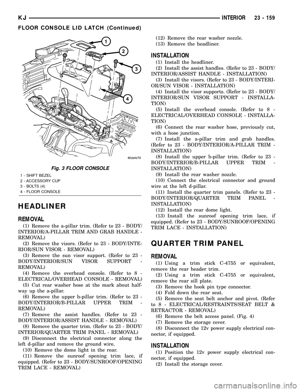
Fig. 3 FLOOR CONSOLE
1 - SHIFT BEZEL
2 - ACCESSORY CUP
3 - BOLTS (4)
4 - FLOOR CONSOLE
KJINTERIOR 23 - 159
FLOOR CONSOLE LID LATCH (Continued)
Page 1646 of 1803
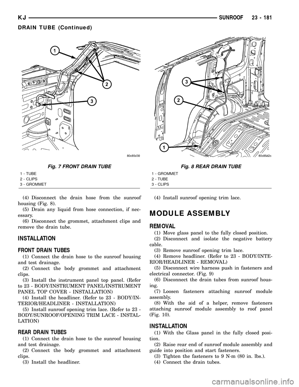
(4) Disconnect the drain hose from the sunroof
housing (Fig. 8).
(5) Drain any liquid from hose connection, if nec-
essary.
(6) Disconnect the grommet, attachment clips and
remove the drain tube.
INSTALLATION
FRONT DRAIN TUBES
(1) Connect the drain hose to the sunroof housing
and test drainage.
(2) Connect the body grommet and attachment
clips.
(3) Install the instrument panel top panel. (Refer
to 23 - BODY/INSTRUMENT PANEL/INSTRUMENT
PANEL TOP COVER - INSTALLATION)
(4) Install the headliner. (Refer to 23 - BODY/IN-
TERIOR/HEADLINER - INSTALLATION)
(5) Install sunroof opening trim lace. (Refer to 23 -
BODY/SUNROOF/OPENING TRIM LACE - INSTAL-
LATION)
REAR DRAIN TUBES
(1) Connect the drain hose to the sunroof housing
and test drainage.
(2) Connect the body grommet and attachment
clips.
(3) Install the headliner.(4) Install sunroof opening trim lace.
MODULE ASSEMBLY
REMOVAL
(1) Move glass panel to the fully closed position.
(2) Disconnect and isolate the negative battery
cable.
(3) Remove sunroof opening trim lace.
(4) Remove headliner. (Refer to 23 - BODY/INTE-
RIOR/HEADLINER - REMOVAL)
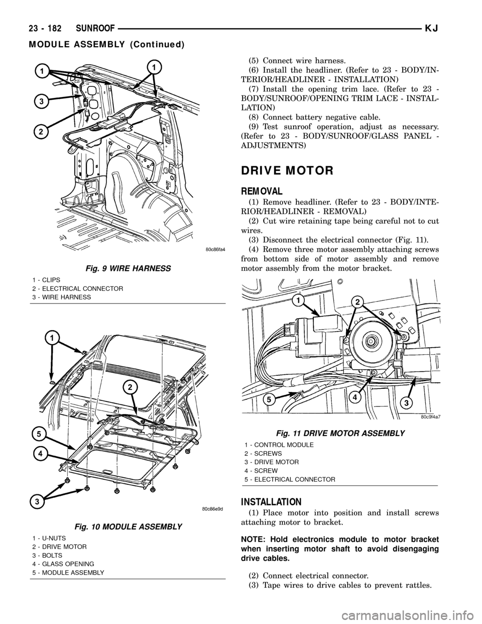
(5) Disconnect wire harness push in fasteners and
electrical connector. (Fig. 9)
(6) Disconnect the drain tubes from sunroof hous-
ing.
(7) Loosen fasteners attaching sunroof module
assembly.
(8) With the aid of a helper, remove fasteners
attaching sunroof module assembly to roof panel
(Fig. 10).
INSTALLATION
(1) With the Glass panel in the fully closed posi-
tion.
(2) Raise rear end of sunroof module assembly and
guide into position and start fasteners.
(3) Tighten the fasteners to 9 N´m (80 in. lbs.).
(4) Connect the drain tubes.
Fig. 7 FRONT DRAIN TUBE
1 - TUBE
2 - CLIPS
3 - GROMMET
Fig. 8 REAR DRAIN TUBE
1 - GROMMET
2 - TUBE
3 - CLIPS
KJSUNROOF 23 - 181
DRAIN TUBE (Continued)
Page 1647 of 1803
(5) Connect wire harness.
(6) Install the headliner. (Refer to 23 - BODY/IN-
TERIOR/HEADLINER - INSTALLATION)
(7) Install the opening trim lace. (Refer to 23 -
BODY/SUNROOF/OPENING TRIM LACE - INSTAL-
LATION)
(8) Connect battery negative cable.
(9) Test sunroof operation, adjust as necessary.
(Refer to 23 - BODY/SUNROOF/GLASS PANEL -
ADJUSTMENTS)
DRIVE MOTOR
REMOVAL
(1) Remove headliner. (Refer to 23 - BODY/INTE-
RIOR/HEADLINER - REMOVAL)
(2) Cut wire retaining tape being careful not to cut
wires.
(3) Disconnect the electrical connector (Fig. 11).
(4) Remove three motor assembly attaching screws
from bottom side of motor assembly and remove
motor assembly from the motor bracket.
INSTALLATION
(1) Place motor into position and install screws
attaching motor to bracket.
NOTE: Hold electronics module to motor bracket
when inserting motor shaft to avoid disengaging
drive cables.
(2) Connect electrical connector.
(3) Tape wires to drive cables to prevent rattles.
Fig. 9 WIRE HARNESS
1 - CLIPS
2 - ELECTRICAL CONNECTOR
3 - WIRE HARNESS
Fig. 10 MODULE ASSEMBLY
1 - U-NUTS
2 - DRIVE MOTOR
3 - BOLTS
4 - GLASS OPENING
5 - MODULE ASSEMBLY
Fig. 11 DRIVE MOTOR ASSEMBLY
1 - CONTROL MODULE
2 - SCREWS
3 - DRIVE MOTOR
4 - SCREW
5 - ELECTRICAL CONNECTOR
23 - 182 SUNROOFKJ
MODULE ASSEMBLY (Continued)
Page 1648 of 1803
(4) Test sunroof operation, adjust as necessary.
(5) Install headliner. (Refer to 23 - BODY/INTERI-
OR/HEADLINER - INSTALLATION)
CONTROL MODULE
REMOVAL
(1) Remove the module assembly. (Refer to 23 -
BODY/SUNROOF/MODULE ASSEMBLY -
REMOVAL)
(2) Remove three motor assembly retaining screws
from bottom side of motor, and remove motor assem-
bly (Fig. 11).
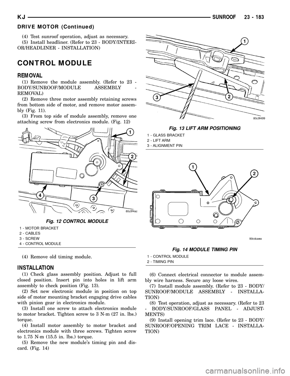
(3) From top side of module assembly, remove one
attaching screw from electronics module. (Fig. 12)
(4) Remove old timing module.
INSTALLATION
(1) Check glass assembly position. Adjust to full
closed position. Insert pin into holes in lift arm
assembly to check position (Fig. 13).
(2) Set new electronic module in position on top
side of motor mounting bracket engaging drive cables
with pinion gear in electronics module.
(3) Install one screw to attach electronics module
to motor bracket. Tighten screw to 3 N´m (27 in. lbs.)
torque.
(4) Install motor assembly to motor bracket and
electronics module with three screws. Tighten screw
to 1.75 N´m (15.5 in. lbs.) torque.
(5) Remove the new module's timing pin and dis-
card. (Fig. 14)(6) Connect electrical connector to module assem-
bly wire harness. Secure any loose wires.
(7) Install module assembly. (Refer to 23 - BODY/
SUNROOF/MODULE ASSEMBLY - INSTALLA-
TION)
(8) Test operation, adjust as necessary. (Refer to 23
- BODY/SUNROOF/GLASS PANEL - ADJUST-
MENTS)
(9) Install opening trim lace. (Refer to 23 - BODY/
SUNROOF/OPENING TRIM LACE - INSTALLA-
TION)
Fig. 12 CONTROL MODULE
1 - MOTOR BRACKET
2 - CABLES
3 - SCREW
4 - CONTROL MODULE
Fig. 13 LIFT ARM POSITIONING
1 - GLASS BRACKET
2 - LIFT ARM
3 - ALIGNMENT PIN
Fig. 14 MODULE TIMING PIN
1 - CONTROL MODULE
2 - TIMING PIN
KJSUNROOF 23 - 183
DRIVE MOTOR (Continued)
Page 1655 of 1803
(1) Connect a tachometer a manifold gauge set or
A/C recycling/charging station.
(2) Set the A/C Heater mode control switch knob in
the Recirculation Mode position, the temperature
control knob in the full cool position, and the blower
motor switch knob in the highest speed position.
(3) Start the engine and hold the idle at 1,000 rpm
with the compressor clutch engaged.
(4) The engine should be at operating temperature.
The doors and windows must be closed.
(5) Insert a thermometer in the driver side center
A/C (panel) outlet. Operate the engine for five min-
utes.
(6) The compressor clutch may cycle, depending
upon the ambient temperature and humidity. If the
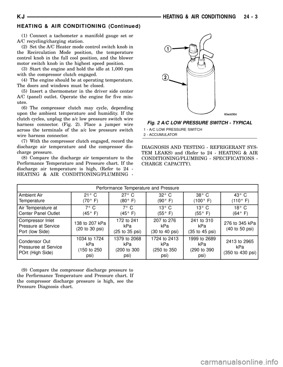
clutch cycles, unplug the a/c low pressure switch wire
harness connector. (Fig. 2). Place a jumper wire
across the terminals of the a/c low pressure switch
wire harness connector.
(7) With the compressor clutch engaged, record the
discharge air temperature and the compressor dis-
charge pressure.
(8) Compare the discharge air temperature to the
Performance Temperature and Pressure chart. If the
discharge air temperature is high, (Refer to 24 -
HEATING & AIR CONDITIONING/PLUMBING -DIAGNOSIS AND TESTING - REFRIGERANT SYS-
TEM LEAKS) and (Refer to 24 - HEATING & AIR
CONDITIONING/PLUMBING - SPECIFICATIONS -
CHARGE CAPACITY).
Performance Temperature and Pressure
Ambient Air
Temperature21É C
(70É F)27É C
(80É F)32É C
(90É F)38É C
(100É F)43É C
(110É F)
Air Temperature at
Center Panel Outlet7É C
(45É F)7É C
(45É F)13É C
(55É F)13É C
(55É F)18É C
(64É F)
Compressor Inlet
Pressure at Service
Port (low Side)138 to 207 kPa
(20 to 30 psi)172 to 241
kPa
(25 to 35 psi)207 to 276
kPa
(30 to 40 psi)241 to 310
kPa
(35 to 45 psi)276 to 345 kPa
(40 to 50 psi)
Condensor Out
Pressuree at Service
POrt (High Side)1034 to 1724
kPa
(150 to 250
psi)1379 to 2068
kPa
(200 to 300
psi)1724 to 2413
kPa
(250 to 350
psi)1999 to 2689
kPa
(290 to 390
psi)2413 to 2965
kPa
(350 to 430 psi)
(9) Compare the compressor discharge pressure to
the Performance Temperature and Pressure chart. If
the compressor discharge pressure is high, see the
Pressure Diagnosis chart.
Fig. 2 A/C LOW PRESSURE SWITCH - TYPICAL
1 - A/C LOW PRESSURE SWITCH
2 - ACCUMULATOR
KJHEATING & AIR CONDITIONING 24 - 3
HEATING & AIR CONDITIONING (Continued)
Page 1661 of 1803
(5) Connect the test set hose or probe to the open
end of the leaking circuit. The test set gauge should
return to the 27 kPa (8 in. Hg.) setting shortly after
each connection is made. If OK, replace the faulty
disconnected component. If not OK, go to Step 6.
(6)
To locate a leak in a vacuum line, leave one end
of the line plugged and connect the test set hose or
probe to the other end of the line. Run your fingers
slowly along the line while watching the test set gauge.
The vacuum reading will fluctuate when your fingers
contact the source of the leak. To repair the vacuum
line, cut out the leaking section of the line. Then, insert
the loose ends of the line into a suitable length of 3 mil-
limeter (0.125 inch) inside diameter rubber hose.
STANDARD PROCEDURE - DIODE
REPLACEMENT
(1) Disconnect the battery negative cable and iso-
late it.
(2) Locate the diode in the harness, and remove
the protective covering.
(3) Remove the diode from the harness, pay atten-
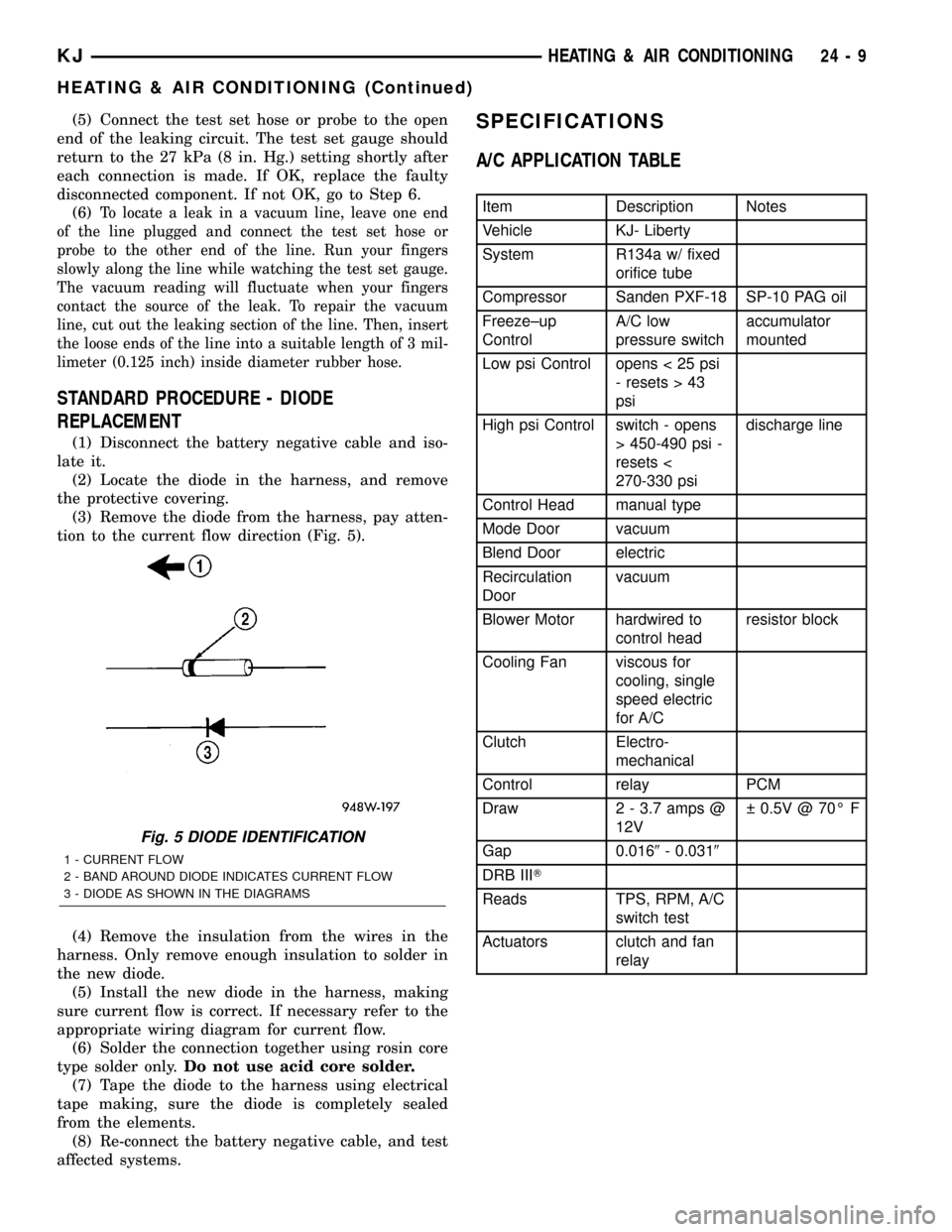
tion to the current flow direction (Fig. 5).
(4) Remove the insulation from the wires in the
harness. Only remove enough insulation to solder in
the new diode.
(5) Install the new diode in the harness, making
sure current flow is correct. If necessary refer to the
appropriate wiring diagram for current flow.
(6) Solder the connection together using rosin core
type solder only.Do not use acid core solder.
(7) Tape the diode to the harness using electrical
tape making, sure the diode is completely sealed
from the elements.
(8) Re-connect the battery negative cable, and test
affected systems.
SPECIFICATIONS
A/C APPLICATION TABLE
Item Description Notes
Vehicle KJ- Liberty
System R134a w/ fixed
orifice tube
Compressor Sanden PXF-18 SP-10 PAG oil
Freeze±up
ControlA/C low
pressure switchaccumulator
mounted
Low psi Control opens < 25 psi
- resets > 43
psi
High psi Control switch - opens
> 450-490 psi -
resets <
270-330 psidischarge line
Control Head manual type
Mode Door vacuum
Blend Door electric
Recirculation
Doorvacuum
Blower Motor hardwired to
control headresistor block
Cooling Fan viscous for
cooling, single
speed electric
for A/C
Clutch Electro-
mechanical
Control relay PCM
Draw 2 - 3.7 amps @
12V 0.5V @ 70É F
Gap 0.0169- 0.0319
DRB IIIT
Reads TPS, RPM, A/C
switch test
Actuators clutch and fan
relay
Fig. 5 DIODE IDENTIFICATION
1 - CURRENT FLOW
2 - BAND AROUND DIODE INDICATES CURRENT FLOW
3 - DIODE AS SHOWN IN THE DIAGRAMS
KJHEATING & AIR CONDITIONING 24 - 9
HEATING & AIR CONDITIONING (Continued)
Page 1665 of 1803
to 2000 rpm. This procedure (burnishing) will seat
the opposing friction surfaces and provide a higher
compressor clutch torque capability.
REMOVAL
The refrigerant system can remain fully-charged
during compressor clutch, rotor, or coil replacement.
The compressor clutch can be serviced in the vehicle.
(1) Disconnect and isolate the battery negative
cable.
(2) Remove the serpentine drive belt(Refer to 7 -
COOLING/ACCESSORY DRIVE/DRIVE BELTS -
REMOVAL).
(3) Unplug the compressor clutch coil wire harness
connector.
(4) Remove the four bolts that secure the compres-
sor to the mounting bracket.
(5) Remove the compressor from the mounting
bracket. Support the compressor in the engine com-
partment while servicing the clutch.
(6) Insert the two pins of the spanner wrench
(Special Tool C-4489 or equivalent) into the holes of
the clutch plate. Hold the clutch plate stationary and
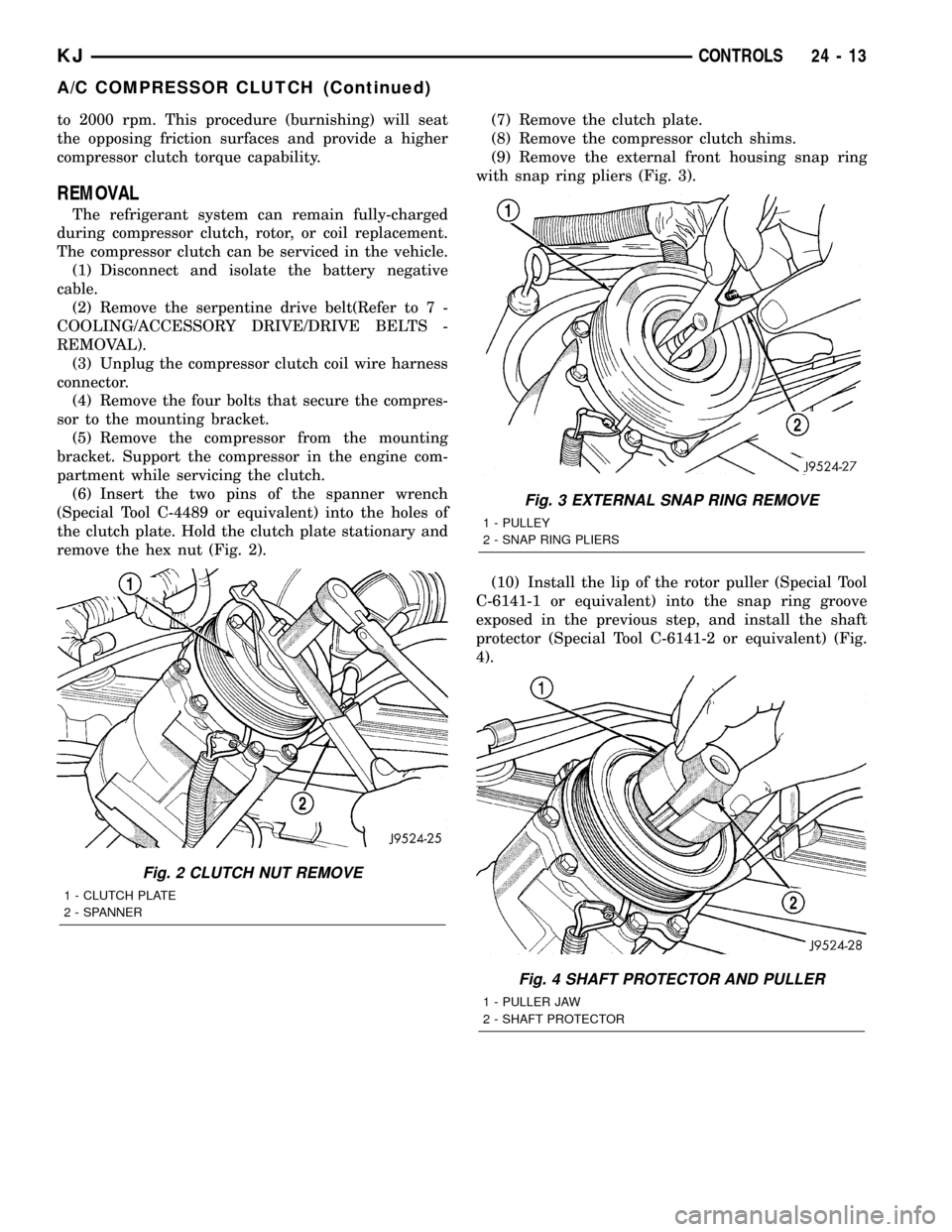
remove the hex nut (Fig. 2).(7) Remove the clutch plate.
(8) Remove the compressor clutch shims.
(9) Remove the external front housing snap ring
with snap ring pliers (Fig. 3).
(10) Install the lip of the rotor puller (Special Tool
C-6141-1 or equivalent) into the snap ring groove
exposed in the previous step, and install the shaft
protector (Special Tool C-6141-2 or equivalent) (Fig.
4).
Fig. 2 CLUTCH NUT REMOVE
1 - CLUTCH PLATE
2 - SPANNER
Fig. 3 EXTERNAL SNAP RING REMOVE
1 - PULLEY
2 - SNAP RING PLIERS
Fig. 4 SHAFT PROTECTOR AND PULLER
1 - PULLER JAW
2 - SHAFT PROTECTOR
KJCONTROLS 24 - 13
A/C COMPRESSOR CLUTCH (Continued)
Page 1666 of 1803
(11) Install the puller through-bolts (Special Tool
C-6461 or equivalent) through the puller flange and
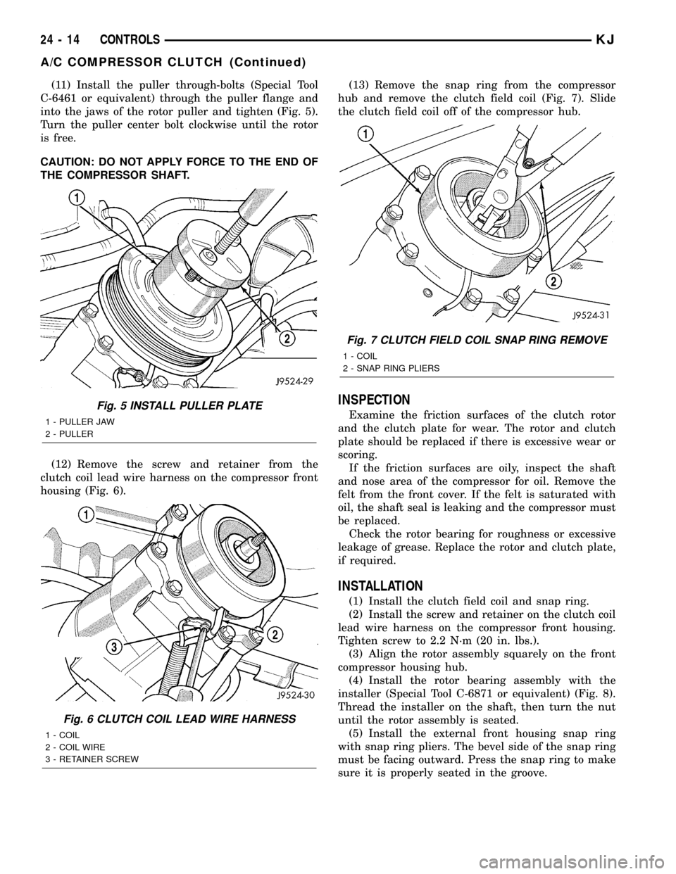
into the jaws of the rotor puller and tighten (Fig. 5).
Turn the puller center bolt clockwise until the rotor
is free.
CAUTION: DO NOT APPLY FORCE TO THE END OF
THE COMPRESSOR SHAFT.
(12) Remove the screw and retainer from the
clutch coil lead wire harness on the compressor front
housing (Fig. 6).(13) Remove the snap ring from the compressor
hub and remove the clutch field coil (Fig. 7). Slide
the clutch field coil off of the compressor hub.
INSPECTION
Examine the friction surfaces of the clutch rotor
and the clutch plate for wear. The rotor and clutch
plate should be replaced if there is excessive wear or
scoring.
If the friction surfaces are oily, inspect the shaft
and nose area of the compressor for oil. Remove the
felt from the front cover. If the felt is saturated with
oil, the shaft seal is leaking and the compressor must
be replaced.
Check the rotor bearing for roughness or excessive
leakage of grease. Replace the rotor and clutch plate,
if required.
INSTALLATION
(1) Install the clutch field coil and snap ring.
(2) Install the screw and retainer on the clutch coil
lead wire harness on the compressor front housing.
Tighten screw to 2.2 N´m (20 in. lbs.).
(3) Align the rotor assembly squarely on the front
compressor housing hub.
(4) Install the rotor bearing assembly with the
installer (Special Tool C-6871 or equivalent) (Fig. 8).
Thread the installer on the shaft, then turn the nut
until the rotor assembly is seated.
(5) Install the external front housing snap ring
with snap ring pliers. The bevel side of the snap ring
must be facing outward. Press the snap ring to make
sure it is properly seated in the groove.
Fig. 5 INSTALL PULLER PLATE
1 - PULLER JAW
2 - PULLER
Fig. 6 CLUTCH COIL LEAD WIRE HARNESS
1 - COIL
2 - COIL WIRE
3 - RETAINER SCREW
Fig. 7 CLUTCH FIELD COIL SNAP RING REMOVE
1 - COIL
2 - SNAP RING PLIERS
24 - 14 CONTROLSKJ
A/C COMPRESSOR CLUTCH (Continued)