2002 JEEP LIBERTY electric
[x] Cancel search: electricPage 1345 of 1803
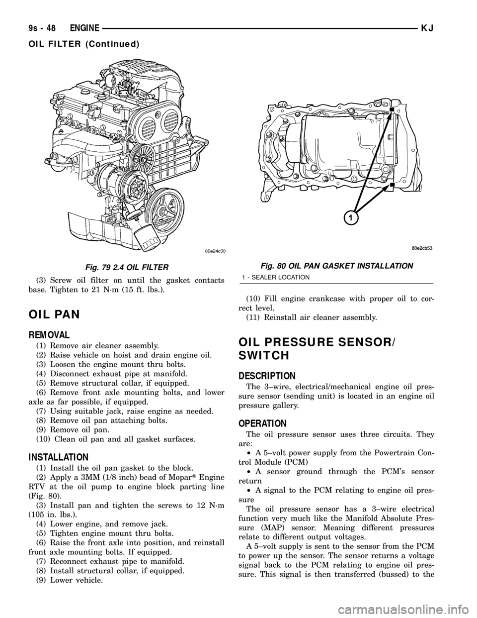
(3) Screw oil filter on until the gasket contacts
base. Tighten to 21 N´m (15 ft. lbs.).
OIL PAN
REMOVAL
(1) Remove air cleaner assembly.
(2) Raise vehicle on hoist and drain engine oil.
(3) Loosen the engine mount thru bolts.
(4) Disconnect exhaust pipe at manifold.
(5) Remove structural collar, if equipped.
(6) Remove front axle mounting bolts, and lower
axle as far possible, if equipped.
(7) Using suitable jack, raise engine as needed.
(8) Remove oil pan attaching bolts.
(9) Remove oil pan.
(10) Clean oil pan and all gasket surfaces.
INSTALLATION
(1) Install the oil pan gasket to the block.
(2) Apply a 3MM (1/8 inch) bead of MopartEngine
RTV at the oil pump to engine block parting line
(Fig. 80).
(3) Install pan and tighten the screws to 12 N´m
(105 in. lbs.).
(4) Lower engine, and remove jack.
(5) Tighten engine mount thru bolts.
(6) Raise the front axle into position, and reinstall
front axle mounting bolts. If equipped.
(7) Reconnect exhaust pipe to manifold.
(8) Install structural collar, if equipped.
(9) Lower vehicle.(10) Fill engine crankcase with proper oil to cor-
rect level.
(11) Reinstall air cleaner assembly.
OIL PRESSURE SENSOR/
SWITCH
DESCRIPTION
The 3±wire, electrical/mechanical engine oil pres-
sure sensor (sending unit) is located in an engine oil
pressure gallery.
OPERATION
The oil pressure sensor uses three circuits. They
are:
²A 5±volt power supply from the Powertrain Con-
trol Module (PCM)
²A sensor ground through the PCM's sensor
return
²A signal to the PCM relating to engine oil pres-
sure
The oil pressure sensor has a 3±wire electrical
function very much like the Manifold Absolute Pres-
sure (MAP) sensor. Meaning different pressures
relate to different output voltages.
A 5±volt supply is sent to the sensor from the PCM
to power up the sensor. The sensor returns a voltage
signal back to the PCM relating to engine oil pres-
sure. This signal is then transferred (bussed) to the
Fig. 79 2.4 OIL FILTERFig. 80 OIL PAN GASKET INSTALLATION
1 - SEALER LOCATION
9s - 48 ENGINEKJ
OIL FILTER (Continued)
Page 1349 of 1803
(2) Spray a small stream of water (Spray Bottle) at
the suspected leak area.
(3) If engine RPM'S change, the area of the sus-
pected leak has been found.
(4) Repair as required.
REMOVAL
(1) Disconnect negative cable from battery.
(2) Disconnect connector from inlet air tempera-
ture sensor.
(3) Disconnect air intake tube at throttle body and
remove upper air cleaner housing.
(4) Disconnect connector from throttle position
sensor (TPS).
(5) Disconnect connector from idle air control (IAC)
motor.
(6) Disconnect connector from MAP sensor.
(7) Remove vacuum lines for purge solenoid and
PCV valve at intake manifold.
(8) Remove vacuum lines for power brake booster,
LDP, EGR transducer, and speed control vacuum res-
ervoir (if equipped) at intake manifold fittings.
(9) Disconnect throttle, speed control (if equipped),
and transaxle control (if equipped) and cables from
throttle lever and bracket. (Refer to 14 - FUEL SYS-
TEM/FUEL INJECTION/THROTTLE CONTROL
CABLE - REMOVAL)
(10) Perform fuel system pressure release proce-
durebefore attempting any repairs.(Refer to 14 -
FUEL SYSTEM/FUEL DELIVERY - STANDARD
PROCEDURE)
(11) Disconnect fuel line. (Refer to 14 - FUEL SYS-
TEM/FUEL DELIVERY/QUICK CONNECT FIT-
TING - STANDARD PROCEDURE)
(12) Disconnect coolant temperature sensor/fuel
injector wire harness connector.
(13) Disconnect fuel injector harness.
(14) Remove intake manifold to cylinder head fas-
teners.
(15) Remove the manifold from engine.
CAUTION: Cover intake manifold openings to pre-
vent foreign material from entering engine.
(16) Inspect the manifold. (Refer to 9 - ENGINE/
MANIFOLDS/INTAKE MANIFOLD - INSPECTION)
INSPECTION
(1) Check manifold surfaces for flatness with
straight edge. Surface must be flat within 0.15 mm
per 300 mm (0.006 in. per foot) of manifold length.
(2) Inspect manifold for cracks or distortion.
Replace manifold if necessary.
INSTALLATION
(1) Clean manifold sealing surfaces.
(2) Install new manifold to cylinder head seals.
(3) Install manifold to head.
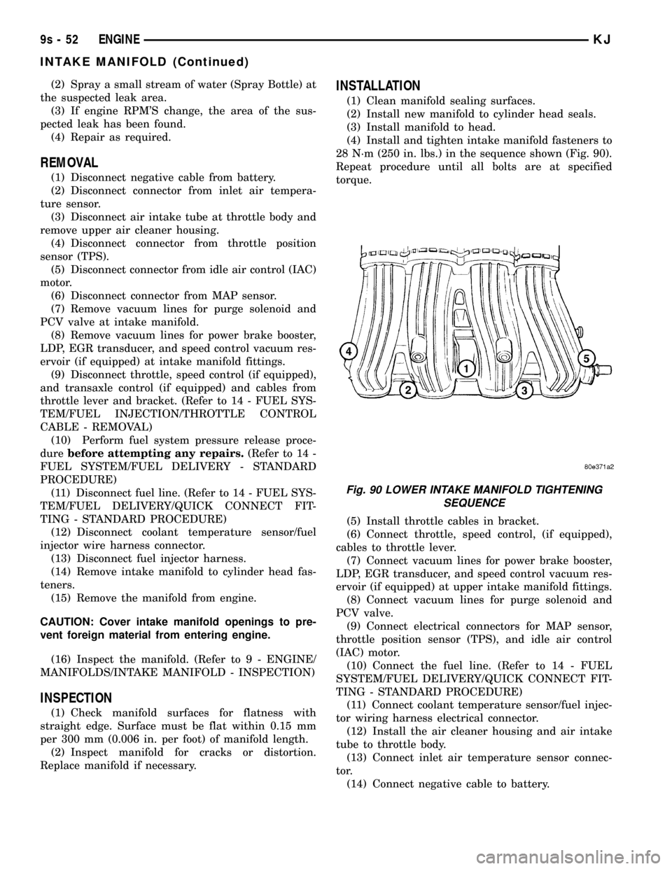
(4) Install and tighten intake manifold fasteners to
28 N´m (250 in. lbs.) in the sequence shown (Fig. 90).
Repeat procedure until all bolts are at specified
torque.
(5) Install throttle cables in bracket.
(6) Connect throttle, speed control, (if equipped),
cables to throttle lever.
(7) Connect vacuum lines for power brake booster,
LDP, EGR transducer, and speed control vacuum res-
ervoir (if equipped) at upper intake manifold fittings.
(8) Connect vacuum lines for purge solenoid and
PCV valve.
(9) Connect electrical connectors for MAP sensor,
throttle position sensor (TPS), and idle air control
(IAC) motor.
(10) Connect the fuel line. (Refer to 14 - FUEL
SYSTEM/FUEL DELIVERY/QUICK CONNECT FIT-
TING - STANDARD PROCEDURE)
(11) Connect coolant temperature sensor/fuel injec-
tor wiring harness electrical connector.
(12) Install the air cleaner housing and air intake
tube to throttle body.
(13) Connect inlet air temperature sensor connec-
tor.
(14) Connect negative cable to battery.
Fig. 90 LOWER INTAKE MANIFOLD TIGHTENING
SEQUENCE
9s - 52 ENGINEKJ
INTAKE MANIFOLD (Continued)
Page 1374 of 1803
FRAMES & BUMPERS
TABLE OF CONTENTS
page page
FRONT FASCIA
REMOVAL.............................1
INSTALLATION..........................2
REAR FASCIA
REMOVAL.............................2
INSTALLATION..........................2
REAR FASCIA SUPPORT
REMOVAL.............................3
INSTALLATION..........................3
FRAME
SPECIFICATIONS
SPECIFICATIONS - FRAME DIMENSIONS . . . 3
SPECIFICATIONS - TORQUE.............6
FRONT SKID PLATE
REMOVAL.............................6
INSTALLATION..........................6
ENGINE CRADLE CROSSMEMBER
REMOVAL.............................6
INSTALLATION..........................6TRANSFER CASE SKID PLATE
REMOVAL.............................7
INSTALLATION..........................7
REAR CROSSMEMBER
REMOVAL.............................7
INSTALLATION..........................7
FRONT TOW HOOK
REMOVAL.............................8
INSTALLATION..........................8
REAR TOW HOOK
REMOVAL.............................8
INSTALLATION..........................8
TRAILER HITCH
REMOVAL.............................9
INSTALLATION..........................9
FUEL TANK SKID PLATE
REMOVAL.............................9
INSTALLATION..........................9
FRONT FASCIA
REMOVAL
(1) Remove the grille. (Refer to 23 - BODY/EXTE-
RIOR/GRILLE - REMOVAL)
(2) Raise and support vehicle.
(3) Remove the front wheel opening flare moldings.
(Refer to 23 - BODY/EXTERIOR/FRONT WHEEL
OPENING FLARE MOLDINGS - REMOVAL)
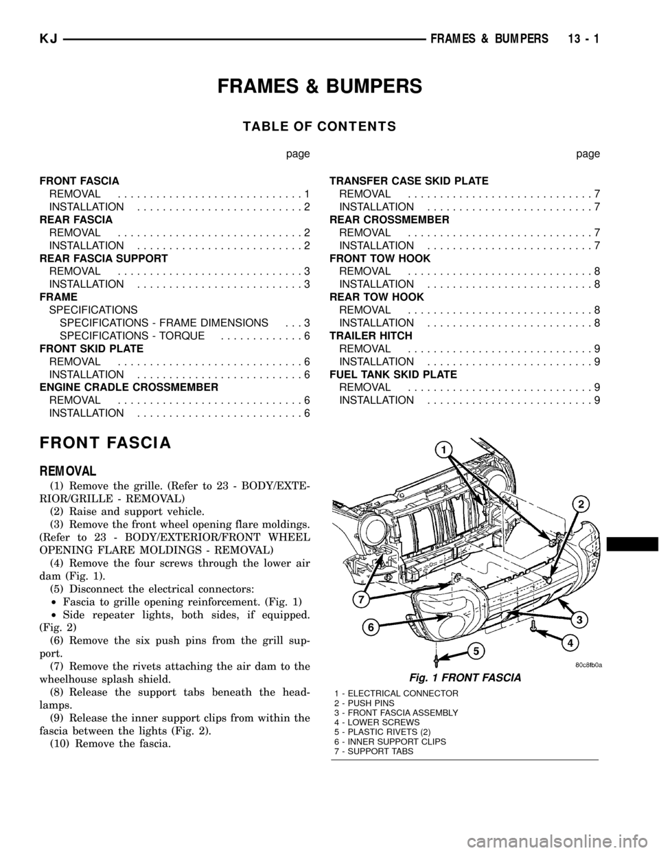
(4) Remove the four screws through the lower air
dam (Fig. 1).
(5) Disconnect the electrical connectors:
²Fascia to grille opening reinforcement. (Fig. 1)
²Side repeater lights, both sides, if equipped.
(Fig. 2)
(6) Remove the six push pins from the grill sup-
port.
(7) Remove the rivets attaching the air dam to the
wheelhouse splash shield.
(8) Release the support tabs beneath the head-
lamps.
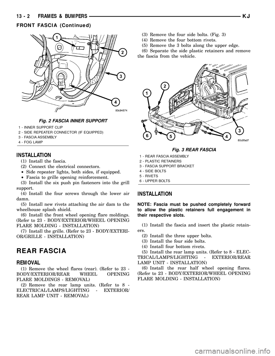
(9) Release the inner support clips from within the
fascia between the lights (Fig. 2).
(10) Remove the fascia.
Fig. 1 FRONT FASCIA
1 - ELECTRICAL CONNECTOR
2 - PUSH PINS
3 - FRONT FASCIA ASSEMBLY
4 - LOWER SCREWS
5 - PLASTIC RIVETS (2)
6 - INNER SUPPORT CLIPS
7 - SUPPORT TABS
KJFRAMES & BUMPERS 13 - 1
Page 1375 of 1803
INSTALLATION
(1) Install the fascia.
(2) Connect the electrical connectors.
²Side repeater lights, both sides, if equipped.
²Fascia to grille opening reinforcement.
(3) Install the six push pin fasteners into the grill
support.
(4) Install the four screws through the lower air
damn.
(5) Install new rivets attaching the air dam to the
wheelhouse splash shield.
(6) Install the front wheel opening flare moldings.
(Refer to 23 - BODY/EXTERIOR/WHEEL OPENING
FLARE MOLDING - INSTALLATION)
(7) Install the grille. (Refer to 23 - BODY/EXTERI-
OR/GRILLE - INSTALLATION)
REAR FASCIA
REMOVAL
(1) Remove the wheel flares (rear). (Refer to 23 -
BODY/EXTERIOR/REAR WHEEL OPENING
FLARE MOLDINGS - REMOVAL)
(2) Remove the rear lamp units. (Refer to 8 -
ELECTRICAL/LAMPS/LIGHTING - EXTERIOR/
REAR LAMP UNIT - REMOVAL)(3) Remove the four side bolts. (Fig. 3)
(4) Remove the four bottom rivets.
(5) Remove the 3 bolts along the upper edge.
(6) Separate the side plastic retainers and remove
the fascia from the vehicle.
INSTALLATION
NOTE: Fascia must be pushed completely forward
to allow the plastic retainers full engagement in
their respective slots.
(1) Install the fascia and insert the plastic retain-
ers.
(2) Install the three upper bolts.
(3) Install the four side bolts.
(4) Install four bottom rivets.
(5) Install the rear lamp units. (Refer to 8 - ELEC-
TRICAL/LAMPS/LIGHTING - EXTERIOR/REAR
LAMP UNIT - INSTALLATION)
(6) Install the rear half wheel opening flares.
(Refer to 23 - BODY/EXTERIOR/WHEEL OPENING
FLARE MOLDING - INSTALLATION)
Fig. 2 FASCIA INNER SUPPORT
1 - INNER SUPPORT CLIP
2 - SIDE REPEATER CONNECTOR (IF EQUIPPED)
3 - FASCIA ASSEMBLY
4 - FOG LAMP
Fig. 3 REAR FASCIA
1 - REAR FASCIA ASSEMBLY
2 - PLASTIC RETAINERS
3 - FASCIA SUPPORT BRACKET
4 - SIDE BOLTS
5 - RIVETS
6 - UPPER BOLTS
13 - 2 FRAMES & BUMPERSKJ
FRONT FASCIA (Continued)
Page 1382 of 1803
TRAILER HITCH
REMOVAL
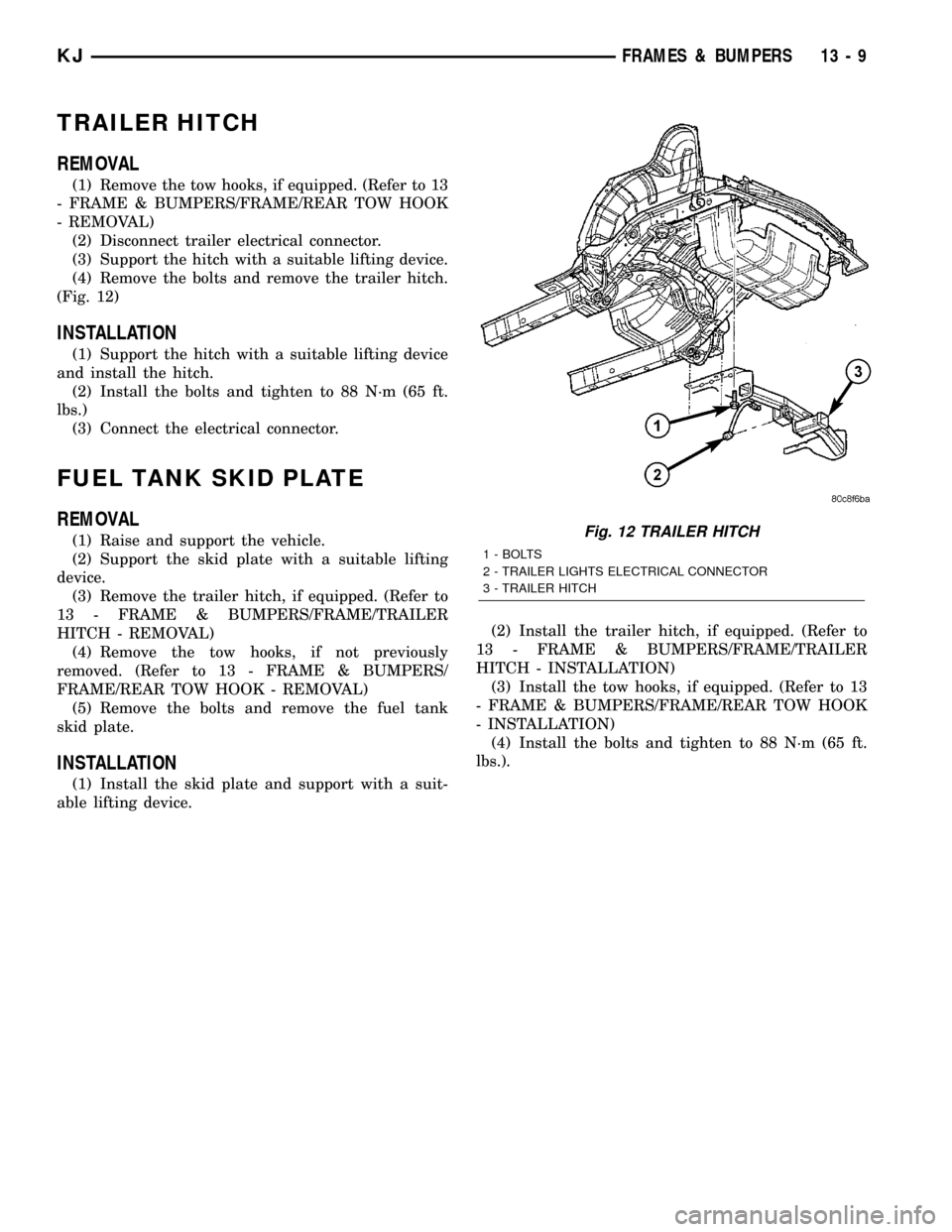
(1) Remove the tow hooks, if equipped. (Refer to 13
- FRAME & BUMPERS/FRAME/REAR TOW HOOK
- REMOVAL)
(2) Disconnect trailer electrical connector.
(3) Support the hitch with a suitable lifting device.
(4) Remove the bolts and remove the trailer hitch.
(Fig. 12)
INSTALLATION
(1) Support the hitch with a suitable lifting device
and install the hitch.
(2) Install the bolts and tighten to 88 N´m (65 ft.
lbs.)
(3) Connect the electrical connector.
FUEL TANK SKID PLATE
REMOVAL
(1) Raise and support the vehicle.
(2) Support the skid plate with a suitable lifting
device.
(3) Remove the trailer hitch, if equipped. (Refer to
13 - FRAME & BUMPERS/FRAME/TRAILER
HITCH - REMOVAL)
(4) Remove the tow hooks, if not previously
removed. (Refer to 13 - FRAME & BUMPERS/
FRAME/REAR TOW HOOK - REMOVAL)
(5) Remove the bolts and remove the fuel tank
skid plate.
INSTALLATION
(1) Install the skid plate and support with a suit-
able lifting device.(2) Install the trailer hitch, if equipped. (Refer to
13 - FRAME & BUMPERS/FRAME/TRAILER
HITCH - INSTALLATION)
(3) Install the tow hooks, if equipped. (Refer to 13
- FRAME & BUMPERS/FRAME/REAR TOW HOOK
- INSTALLATION)
(4) Install the bolts and tighten to 88 N´m (65 ft.
lbs.).
Fig. 12 TRAILER HITCH
1 - BOLTS
2 - TRAILER LIGHTS ELECTRICAL CONNECTOR
3 - TRAILER HITCH
KJFRAMES & BUMPERS 13 - 9
Page 1384 of 1803
FUEL DELIVERY
DESCRIPTION
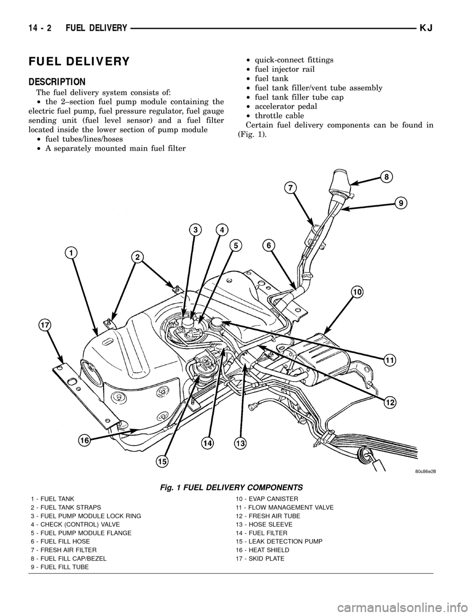
The fuel delivery system consists of:
²the 2±section fuel pump module containing the
electric fuel pump, fuel pressure regulator, fuel gauge
sending unit (fuel level sensor) and a fuel filter
located inside the lower section of pump module
²fuel tubes/lines/hoses
²A separately mounted main fuel filter²quick-connect fittings
²fuel injector rail
²fuel tank
²fuel tank filler/vent tube assembly
²fuel tank filler tube cap
²accelerator pedal
²throttle cable
Certain fuel delivery components can be found in
(Fig. 1).
Fig. 1 FUEL DELIVERY COMPONENTS
1 - FUEL TANK 10 - EVAP CANISTER
2 - FUEL TANK STRAPS 11 - FLOW MANAGEMENT VALVE
3 - FUEL PUMP MODULE LOCK RING 12 - FRESH AIR TUBE
4 - CHECK (CONTROL) VALVE 13 - HOSE SLEEVE
5 - FUEL PUMP MODULE FLANGE 14 - FUEL FILTER
6 - FUEL FILL HOSE 15 - LEAK DETECTION PUMP
7 - FRESH AIR FILTER 16 - HEAT SHIELD
8 - FUEL FILL CAP/BEZEL 17 - SKID PLATE
9 - FUEL FILL TUBE
14 - 2 FUEL DELIVERYKJ
Page 1385 of 1803
OPERATION
Fuel is picked up in the fuel tank by the fuel pump
module. This module is located on the bottom of the
fuel tank.
A fuel return system is provided within the fuel
pump module using check valves. A separate fuel
return line from the engine to the tank is not used.
The fuel pressure regulator and the main fuel filter
are not combined. They are separate items.
The fuel tank assembly consists of: the fuel tank,
fuel pump module assembly, fuel pump module lock
ring/gasket, ORVR components. Refer to 25, Emis-
sion Control System for ORVR information.
A fuel filler/vent tube assembly using a pressure/
vacuum, 1/4 turn fuel filler cap is used. The fuel
filler tube contains a flap door located below the fuel
fill cap. A one-way check valve is installed into the
tanks fuel fill fitting.
Also to be considered part of the fuel system is the
evaporation control system and ORVR system. This
is designed to reduce the emission of fuel vapors into
the atmosphere. The description and function of the
Evaporative Control System is found in 25, Emission
Control Systems.
Both fuel filters (mounted to front of fuel tank, and
inside the bottom fuel pump module) are designed for
extended service. They do not require normal sched-
uled maintenance. The bottom section of the fuel
pump module (with included filter) should only be
replaced if a diagnostic procedure indicates to do so.
Also, the fuel filter mounted to the front of the fuel
tank should only be replaced if a diagnostic proce-
dure indicates to do so.
DIAGNOSIS AND TESTING - FUEL PRESSURE
LEAK DOWN TEST
Use this test in conjunction with the Fuel Pump
Pressure Test and Fuel Pump Capacity Test.
Check Valve Operation:The electric fuel pump
outlet contains a one-way check valve to prevent fuel
flow back into the tank and to maintain fuel supply
line pressure (engine warm) when pump is not oper-
ational. It is also used to keep the fuel supply line
full of gasoline when pump is not operational. After
the vehicle has cooled down, fuel pressure may drop
to 0 psi (cold fluid contracts), but liquid gasoline will
remain in fuel supply line between the check valve
and fuel injectors.Fuel pressure that has
dropped to 0 psi on a cooled down vehicle
(engine off) is a normal condition.When the elec-
tric fuel pump is activated, fuel pressure should
immediately(1±2 seconds) rise to specification.
Abnormally long periods of cranking to restart a
hotengine that has been shut down for a short
period of time may be caused by:
²Fuel pressure bleeding past a fuel injector(s).²Fuel pressure bleeding past the check valve in
the fuel pump module.
(1) Disconnect the fuel inlet line at fuel rail. Refer
to Quick Connect Fittings for procedures. On some
engines, air cleaner housing removal may be neces-
sary before fuel line disconnection.
(2) Obtain correct Fuel Line Pressure Test Adapter
Tool Hose. Tool number 6539 is used for 5/16º fuel
lines and tool number 6631 is used for 3/8º fuel lines.
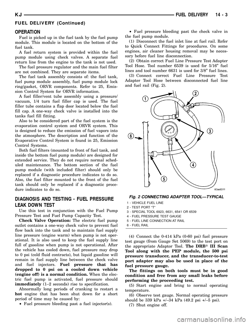
(3) Connect correct Fuel Line Pressure Test
Adapter Tool Hose between disconnected fuel line
and fuel rail (Fig. 2).
(4) Connect the 0-414 kPa (0-60 psi) fuel pressure
test gauge (from Gauge Set 5069) to the test port on
the appropriate Adaptor Tool.The DRBtIII Scan
Tool along with the PEP module, the 500 psi
pressure transducer, and the transducer-to-test
port adapter may also be used in place of the
fuel pressure gauge.
The fittings on both tools must be in good
condition and free from any small leaks before
performing the proceeding test.
(5) Start engine and bring to normal operating
temperature.
(6) Observe test gauge. Normal operating pressure
should be 339 kPa +/±34 kPa (49.2 psi +/±5 psi).
(7) Shut engine off.
Fig. 2 CONNECTING ADAPTER TOOLÐTYPICAL
1 - VEHICLE FUEL LINE
2 - TEST PORT ªTº
3 - SPECIAL TOOL 6923, 6631, 6541 OR 6539
4 - FUEL PRESSURE TEST GAUGE
5 - FUEL LINE CONNECTION AT RAIL
6 - FUEL RAIL
KJFUEL DELIVERY 14 - 3
FUEL DELIVERY (Continued)
Page 1386 of 1803
(8) Pressure should not fall below30 psi for five
minutes.
(9) If pressure falls below 30 psi, it must be deter-
mined if a fuel injector, the check valve within the
fuel pump module, or a fuel tube/line is leaking.
(10) Again, start engine and bring to normal oper-
ating temperature.
(11) Shut engine off.
(12)Testing for fuel injector or fuel rail leak-
age:Clamp off the rubber hose portion of Adaptor
Tool between the fuel rail and the test port ªTº on
Adapter Tool. If pressure now holds at or above 30
psi, a fuel injector or the fuel rail is leaking.
(13)Testing for fuel pump check valve, filter,
regulator check valve or fuel tube/line leakage:
Clamp off the rubber hose portion of Adaptor Tool
between the vehicle fuel line and test port ªTº on
Adapter Tool. If pressure now holds at or above 30
psi, a leak may be found at a fuel tube/line. If no
leaks are found at fuel tubes or lines, one of the
check valves in either the electric fuel pump, fuel fil-
ter or fuel pressure regulator may be leaking.
Note: A quick loss of pressure usually indicates a
defective check valve in the pressure regulator. A
slow loss of pressure usually indicates a defective
check valve in the bottom of the fuel pump module.
The check valves are not serviced separately. Also,
the electric fuel pump is not serviced separately.
STANDARD PROCEDURE - FUEL SYSTEM
PRESSURE RELEASE
Use following procedure if the fuel injector
rail is, or is not equipped with a fuel pressure
test port.
(1) Remove fuel fill cap.
(2) Remove fuel pump relay from Power Distribu-
tion Center (PDC). For location of relay, refer to label
on underside of PDC cover.(3) Start and run engine until it stalls.
(4) Attempt restarting engine until it will no
longer run.
(5) Turn ignition key to OFF position.
CAUTION: Steps 1, 2, 3 and 4 must be performed to
relieve high pressure fuel from within fuel rail. Do
not attempt to use following steps to relieve this
pressure as excessive fuel will be forced into a cyl-
inder chamber.
(6) Unplug connector from any fuel injector.
(7) Attach one end of a jumper wire with alligator
clips (18 gauge or smaller) to either injector terminal.
(8) Connect other end of jumper wire to positive
side of battery.
(9) Connect one end of a second jumper wire to
remaining injector terminal.
CAUTION: Powering an injector for more than a few
seconds will permanently damage the injector.
(10) Momentarily touch other end of jumper wire
to negative terminal of battery for no more than a
few seconds.
(11) Place a rag or towel below fuel line quick-con-
nect fitting at fuel rail.
(12) Disconnect quick-connect fitting at fuel rail.
Refer to Quick-Connect Fittings.
(13) Return fuel pump relay to PDC.
(14) One or more Diagnostic Trouble Codes (DTC's)
may have been stored in PCM memory due to fuel
pump relay removal. The DRBtscan tool must be
used to erase a DTC.
14 - 4 FUEL DELIVERYKJ
FUEL DELIVERY (Continued)