2002 JEEP LIBERTY Transmission speed sensor
[x] Cancel search: Transmission speed sensorPage 1164 of 1803

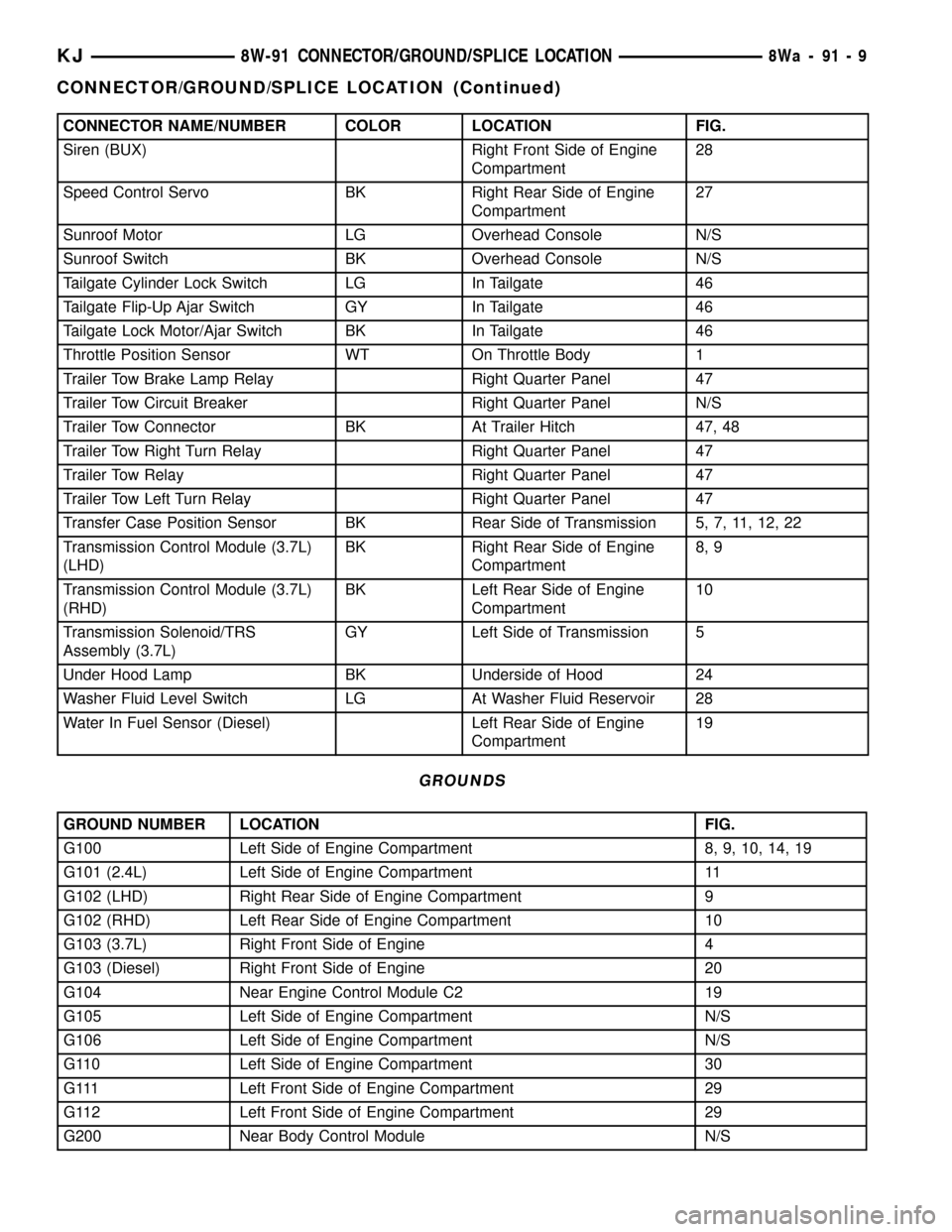
CONNECTOR NAME/NUMBER COLOR LOCATION FIG.
Siren (BUX) Right Front Side of Engine
Compartment28
Speed Control Servo BK Right Rear Side of Engine
Compartment27
Sunroof Motor LG Overhead Console N/S
Sunroof Switch BK Overhead Console N/S
Tailgate Cylinder Lock Switch LG In Tailgate 46
Tailgate Flip-Up Ajar Switch GY In Tailgate 46
Tailgate Lock Motor/Ajar Switch BK In Tailgate 46
Throttle Position Sensor WT On Throttle Body 1
Trailer Tow Brake Lamp Relay Right Quarter Panel 47
Trailer Tow Circuit Breaker Right Quarter Panel N/S
Trailer Tow Connector BK At Trailer Hitch 47, 48
Trailer Tow Right Turn Relay Right Quarter Panel 47
Trailer Tow Relay Right Quarter Panel 47
Trailer Tow Left Turn Relay Right Quarter Panel 47
Transfer Case Position Sensor BK Rear Side of Transmission 5, 7, 11, 12, 22
Transmission Control Module (3.7L)
(LHD)BK Right Rear Side of Engine
Compartment8, 9
Transmission Control Module (3.7L)
(RHD)BK Left Rear Side of Engine
Compartment10
Transmission Solenoid/TRS
Assembly (3.7L)GY Left Side of Transmission 5
Under Hood Lamp BK Underside of Hood 24
Washer Fluid Level Switch LG At Washer Fluid Reservoir 28
Water In Fuel Sensor (Diesel) Left Rear Side of Engine
Compartment19
GROUNDS
GROUND NUMBER LOCATION FIG.
G100 Left Side of Engine Compartment 8, 9, 10, 14, 19
G101 (2.4L) Left Side of Engine Compartment 11
G102 (LHD) Right Rear Side of Engine Compartment 9
G102 (RHD) Left Rear Side of Engine Compartment 10
G103 (3.7L) Right Front Side of Engine 4
G103 (Diesel) Right Front Side of Engine 20
G104 Near Engine Control Module C2 19
G105 Left Side of Engine Compartment N/S
G106 Left Side of Engine Compartment N/S
G110 Left Side of Engine Compartment 30
G111 Left Front Side of Engine Compartment 29
G112 Left Front Side of Engine Compartment 29
G200 Near Body Control Module N/S
KJ8W-91 CONNECTOR/GROUND/SPLICE LOCATION8Wa-91-9
CONNECTOR/GROUND/SPLICE LOCATION (Continued)
Page 1226 of 1803

NOTE: Recheck bolt torque for engine lift plate
before removing engine.
(30) Secure the left and right engine wiring har-
nesses away from engine.
(31) Raise vehicle.
(32) Disconnect oxygen sensor wiring.
(33) Disconnect crankshaft postion sensor.
(34) Disconnect the engine block heater power
cable, if equipped.
(35) Disconnect the front propshaft at the front
differential and secure out of way.
NOTE: It is necessary to disconnect the front prop-
shaft for access to the starter and left side exhaust
flange.
(36) Remove the starter.
(37) Remove the ground straps from the left and
right side of the block.
(38) Disconnect the right and left exhaust pipes at
the manifolds and from the crossover, and remove
from the vehicle.
NOTE: The exhaust clamps at the manifolds cannot
be reused. New clamps must be used or leaks may
occur.
NOTE: For manual transmission vehicles, the trans-
mission must be removed from the vehicle, before
the engine can be removed. The manual transmis-
sion will contact the floorpan before the engine
clears the motor mounts, so it must be removed.
(39) Remove the structural cover.
(40) Remove torque convertor bolts, and mark
location for reassembly.
(41) Remove transmission bellhousing to engine
bolts.
(42) Loosen left and right engine mount thru bolts.
NOTE: It is not necessary to completely remove
engine mount thru bolts, for engine removal.
(43) Lower the vehicle.
(44) Support the transmission with a suitable jack.
(45) Connect a suitable engine hoist to the engine
lift plate.
(46) Remove engine from vehicle.
INSTALLATION
(1) Position the engine in the vehicle.
(2) Install both left and right side engine mounts
onto engine.
(3) Raise the vehicle.(4) Install the transmission bellhousing to engine
mounting bolts. Tighten the bolts to 41 N´m (30ft.
lbs.).
(5) Tighten the engine mount thru bolts.
(6) Install the torque convertor bolts.
(7) Connect the ground straps on the left and right
side of the engine.
(8) Install the starter.
(9) Connect the crankshaft position sensor.
(10) Install the engine block heater power cable, if
equipped.
CAUTION: The structural cover requires a specific
torque sequence. Failure to follow this sequence
may cause severe damage to the cover.
(11) Install the structural cover.
NOTE: New clamps must be used on exhaust man-
ifold flanges. Failure to use new clamps may result
in exhaust leaks.
(12) Install the left and right exhaust pipes.
(13) Connect the left and right oxygen sensors.
(14) Lower vehicle.
(15) Remove the engine lift plate.
(16) Connect the knock sensors.
(17) Connect the engine to body ground straps at
the left side of the cowl.
(18) Install the intake manifold.
(19) Install the engine oil dipstick tube.
(20) Install the power brake booster vacuum hose.
(21) Install the breather hoses.
(22) Install the PCV hose.
(23) Install the fuel rail.
(24) Install the coil over plugs.
(25) Connect the engine wiring harness at the fol-
lowing points:
²Intake air temperature (IAT) sensor
²Fuel Injectors
²Throttle Position (TPS) Switch
²Idle Air Control (IAC) Motor
²Engine Oil Pressure Switch
²Engine Coolant Temperature (ECT) Sensor
²Manifold Absolute Pressure MAP) Sensor
²Camshaft Position (CMP) Sensor
²Coil Over Plugs
²Crankshaft Position Sensor
(26) Connect lower radiator hose.
(27) Connect upper radiator hose.
(28) Connect throttle and speed control cables.
(29) Install the heater hose assembly.
(30) Install coolant recovery bottle.
(31) Install the power steering pump.
(32) Install the generator.
(33) Install the A/C compressor.
(34) Install the drive belt.
KJENGINE - 3.7L 9 - 11
ENGINE - 3.7L (Continued)
Page 1254 of 1803

ENGINE BLOCK
DESCRIPTION
The cylinder block is made of cast iron. The block
is a closed deck design with the left bank forward. To
provide high rigidity and improved NVH an
enhanced compacted graphite bedplate (Fig. 31) is
bolted to the block. The block design allows coolant
flow between the cylinders bores, and an internal
coolant bypass to a single poppet inlet thermostat is
included in the cast aluminum front cover.
STANDARD PROCEDURE - CYLINDER BORE
HONING
Before honing, stuff plenty of clean shop towels
under the bores and over the crankshaft to keep
abrasive materials from entering the crankshaft
area.
(1) Used carefully, the Cylinder Bore Sizing Hone
C-823, equipped with 220 grit stones, is the best tool
for this job. In addition to deglazing, it will reduce
taper and out-of-round, as well as removing light
scuffing, scoring and scratches. Usually, a few strokes
will clean up a bore and maintain the required lim-
its.
CAUTION: DO NOT use rigid type hones to remove
cylinder wall glaze.
(2) Deglazing of the cylinder walls may be done if
the cylinder bore is straight and round. Use a cylin-
der surfacing hone, Honing Tool C-3501, equipped
with 280 grit stones (C-3501-3810). about 20-60
strokes, depending on the bore condition, will be suf-
ficient to provide a satisfactory surface. Using honingoil C-3501-3880, or a light honing oil, available from
major oil distributors.
CAUTION: DO NOT use engine or transmission oil,
mineral spirits, or kerosene.
(3) Honing should be done by moving the hone up
and down fast enough to get a crosshatch pattern.
The hone marks should INTERSECT at 50É to 60É
for proper seating of rings (Fig. 32).
(4) A controlled hone motor speed between 200 and
300 RPM is necessary to obtain the proper cross-
hatch angle. The number of up and down strokes per
minute can be regulated to get the desired 50É to 60É
angle. Faster up and down strokes increase the cross-
hatch angle.
(5) After honing, it is necessary that the block be
cleaned to remove all traces of abrasive. Use a brush
to wash parts with a solution of hot water and deter-
gent. Dry parts thoroughly. Use a clean, white, lint-
free cloth to check that the bore is clean. Oil the
bores after cleaning to prevent rusting.
CLEANING
Thoroughly clean the oil pan and engine block gas-
ket surfaces.
Use compressed air to clean out:
²The galley at the oil filter adaptor hole.
²The front and rear oil galley holes.
²The feed holes for the crankshaft main bearings.
Fig. 31 CYLINDER BLOCK BEDPLATE
1 - Cylinder Block Bedplate
2 - Crankshaft Position Sensor
3 - Crankshaft Main Bearing Caps
Fig. 32 Cylinder Bore Crosshatch Pattern
1 - CROSSHATCH PATTERN
2 - INTERSECT ANGLE
KJENGINE - 3.7L 9 - 39
Page 1309 of 1803

NOTE: Plastigage is available in a variety of clear-
ance ranges. Use the most appropriate range for
the specifications you are checking.
(4) Install the proper crankshaft bearings to
achieve the specified bearing clearances. (Refer to 9 -
ENGINE/ENGINE BLOCK/CRANKSHAFT MAIN
BEARINGS - STANDARD PROCEDURE) (Refer to 9
- ENGINE/ENGINE BLOCK/CONNECTING ROD
BEARINGS - STANDARD PROCEDURE)
REMOVAL - ENGINE ASSEMBLY
(1) Disconnect the battery negative cable.
(2) Remove hood. Mark hood hinge location for
reinstallation.
(3) Remove air cleaner assembly.
(4) Remove radiator core support bracket.
(5) Remove fan shroud with electric fan assembly.
(6) Remove drive belt.
NOTE: It is NOT necessary to discharge the A/C
system to remove the engine.
(7) Remove A/C compressor and secure away from
engine with lines attached.
(8) Remove generator and secure away from
engine.
NOTE: Do NOT remove the phenolic pulley from the
P/S pump. It is not required for P/S pump removal.
(9) Remove power steering pump with lines
attached and secure away from engine.
(10) Drain cooling system.
(11) Remove coolant bottle.
(12) Disconnect the heater hoses from the engine.
(13) Disconnect heater hoses from heater core and
remove hose assembly.
(14) Disconnect throttle and speed control cables.
(15) Remove upper radiator hose from engine.
(16) Remove lower radiator hose from engine.
(17) Disconnect the engine to body ground straps
at the left side of cowl.
(18) Disconnect the engine wiring harness at the
following points:
²Intake air temperature (IAT) sensor
²Fuel Injectors
²Throttle Position (TPS) Switch
²Idle Air Control (IAC) Motor
²Engine Oil Pressure Switch
²Engine Coolant Temperature (ECT) Sensor
²Manifold Absolute Pressure MAP) Sensor
²Camshaft Position (CMP) Sensor
²Coil Over Plugs
²Crankshaft Position Sensor
(19) Remove coil over plugs.
(20) Release fuel rail pressure.(21) Remove fuel rail and secure away from
engine.
(22) Remove the PCV hose.
(23) Remove the breather hoses.
(24) Remove the vacuum hose for the power brake
booster.
(25) Disconnect knock sensors.
(26) Secure the left and right engine wiring har-
nesses away from engine.
(27) Raise vehicle.
(28) Disconnect oxygen sensor wiring.
(29) Disconnect crankshaft postion sensor.
(30) Disconnect the engine block heater power
cable, if equipped.
(31) Disconnect the front propshaft at the front
differential and secure out of way.
(32) Remove the starter.
(33) Remove the ground straps from the engine
(34) Disconnect the exhaust pipes at the manifold.
(35) Remove the structural cover, if equipped.
(36) Remove torque convertor bolts, and mark
location for reassembly.
(37) Remove transmission bellhousing to engine
bolts.
(38) Loosen left and right engine mount thru bolts.
NOTE: It is not necessary to completely remove
engine mount thru bolts, for engine removal.
(39) Lower the vehicle.
(40) Support the transmission with a suitable jack.
(41) Connect a suitable engine hoist to the engine.
CAUTION: The 2.4L engine with manual transmis-
sions, can be removed without removing the man-
ual transmission. Use caution when attempting this
procedure as the clearance is tight.
(42) Remove engine from vehicle.
INSTALLATION - ENGINE ASSEMBLY
(1) Position the engine in the vehicle.
CAUTION: Use caution when installing 2.4L engine
into vehicle equipped with manual transmission, as
clearance is tight.
(2) Install both left and right side engine mounts
into the frame mounts.
(3) Raise the vehicle.
(4) Install the transmission bellhousing to engine
mounting bolts. Tighten the bolts to 41 N´m (30ft.
lbs.).
(5) Tighten the engine mount thru bolts.
(6) Install the torque convertor bolts.
(7) Connect the ground straps on the left and right
side of the engine.
9s - 12 ENGINEKJ
ENGINE - 2.4L (Continued)
Page 1425 of 1803

WARNING: THE EXHAUST MANIFOLD, EXHAUST
PIPES AND CATALYTIC CONVERTER BECOME
VERY HOT DURING ENGINE OPERATION. ALLOW
ENGINE TO COOL BEFORE REMOVING OXYGEN
SENSOR.
(1) Raise and support vehicle.
(2) Disconnect wire connector from O2S sensor.
CAUTION: When disconnecting sensor electrical
connector, do not pull directly on wire going into
sensor.
(3) Remove O2S sensor with an oxygen sensor
removal and installation tool.
(4) Clean threads in exhaust pipe using appropri-
ate tap.
INSTALLATION
Threads of new oxygen sensors are factory coated
with anti-seize compound to aid in removal.DO
NOT add any additional anti-seize compound to
threads of a new oxygen sensor.
(1) Install O2S sensor. Tighten to 30 N´m (22 ft.
lbs.) torque.
(2) Connect O2S sensor wire connector.
(3) Lower vehicle.
THROTTLE BODY
DESCRIPTION
The throttle body is located on the intake manifold.
Fuel does not enter the intake manifold through the
throttle body. Fuel is sprayed into the manifold by
the fuel injectors.
OPERATION
Filtered air from the air cleaner enters the intake
manifold through the throttle body. The throttle body
contains an air control passage controlled by an Idle
Air Control (IAC) motor. The air control passage is
used to supply air for idle conditions. A throttle valve
(plate) is used to supply air for above idle conditions.
Certain sensors are attached to the throttle body.
The accelerator pedal cable, speed control cable and
transmission control cable (when equipped) are con-
nected to the throttle body linkage arm.
A (factory adjusted) set screw is used to mechani-
cally limit the position of the throttle body throttle
plate.Never attempt to adjust the engine idle
speed using this screw.All idle speed functions are
controlled by the PCM.
REMOVAL
2.4L
A (factory adjusted) set screw is used to mechani-
cally limit the position of the throttle body throttle
plate.Never attempt to adjust the engine idle
speed using this screw.All idle speed functions are
controlled by the Powertrain Control Module (PCM).
(1) Remove air cleaner tube at throttle body.
(2) Disconnect throttle body electrical connectors
at IAC motor and TPS.
(3) Remove all control cables from throttle body
(lever) arm. Refer to the Accelerator Pedal and Throt-
tle Cable section for removal/installation procedures.
(4) Disconnect necessary vacuum lines at throttle
body.
(5) Remove 3 throttle body mounting bolts (Fig.
23).
(6) Remove throttle body from intake manifold.
(7) Check condition of old throttle body-to-intake
manifold o-ring.
3.7L
A (factory adjusted) set screw is used to mechani-
cally limit the position of the throttle body throttle
plate.Never attempt to adjust the engine idle
speed using this screw.All idle speed functions are
controlled by the Powertrain Control Module (PCM).
(1) Remove air cleaner tube at throttle body.
(2) Disconnect throttle body electrical connectors
at IAC motor and TPS.
Fig. 23 THROTTLE BODY MOUNTING BOLTS - 2.4L
1 - THROTTLE BODY
2 - IGNITION COIL
3 - MOUNTING BOLTS (3)
KJFUEL INJECTION 14 - 43
OXYGEN SENSOR (Continued)
Page 1715 of 1803

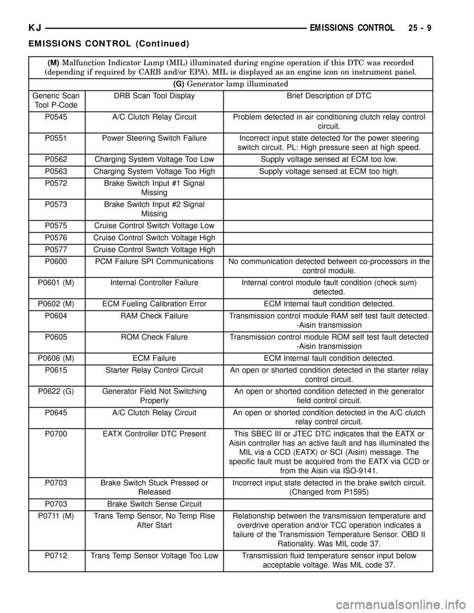
(M)Malfunction Indicator Lamp (MIL) illuminated during engine operation if this DTC was recorded
(depending if required by CARB and/or EPA). MIL is displayed as an engine icon on instrument panel.
(G)Generator lamp illuminated
Generic Scan
Tool P-CodeDRB Scan Tool Display Brief Description of DTC
P0545 A/C Clutch Relay Circuit Problem detected in air conditioning clutch relay control
circuit.
P0551 Power Steering Switch Failure Incorrect input state detected for the power steering
switch circuit. PL: High pressure seen at high speed.
P0562 Charging System Voltage Too Low Supply voltage sensed at ECM too low.
P0563 Charging System Voltage Too High Supply voltage sensed at ECM too high.
P0572 Brake Switch Input #1 Signal
Missing
P0573 Brake Switch Input #2 Signal
Missing
P0575 Cruise Control Switch Voltage Low
P0576 Cruise Control Switch Voltage High
P0577 Cruise Control Switch Voltage High
P0600 PCM Failure SPI Communications No communication detected between co-processors in the
control module.
P0601 (M) Internal Controller Failure Internal control module fault condition (check sum)
detected.
P0602 (M) ECM Fueling Calibration Error ECM Internal fault condition detected.
P0604 RAM Check Failure Transmission control module RAM self test fault detected.
-Aisin transmission
P0605 ROM Check Falure Transmission control module ROM self test fault detected
-Aisin transmission
P0606 (M) ECM Failure ECM Internal fault condition detected.
P0615 Starter Relay Control Circuit An open or shorted condition detected in the starter relay
control circuit.
P0622 (G) Generator Field Not Switching
ProperlyAn open or shorted condition detected in the generator
field control circuit.
P0645 A/C Clutch Relay Circuit An open or shorted condition detected in the A/C clutch
relay control circuit.
P0700 EATX Controller DTC Present This SBEC III or JTEC DTC indicates that the EATX or
Aisin controller has an active fault and has illuminated the
MIL via a CCD (EATX) or SCI (Aisin) message. The
specific fault must be acquired from the EATX via CCD or
from the Aisin via ISO-9141.
P0703 Brake Switch Stuck Pressed or
ReleasedIncorrect input state detected in the brake switch circuit.
(Changed from P1595)
P0703 Brake Switch Sense Circuit
P0711 (M) Trans Temp Sensor, No Temp Rise
After StartRelationship between the transmission temperature and
overdrive operation and/or TCC operation indicates a
failure of the Transmission Temperature Sensor. OBD II
Rationality. Was MIL code 37.
P0712 Trans Temp Sensor Voltage Too Low Transmission fluid temperature sensor input below
acceptable voltage. Was MIL code 37.
KJEMISSIONS CONTROL 25 - 9
EMISSIONS CONTROL (Continued)
Page 1716 of 1803

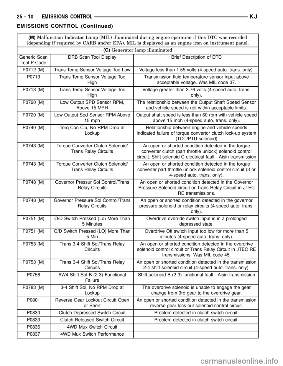
(M)Malfunction Indicator Lamp (MIL) illuminated during engine operation if this DTC was recorded
(depending if required by CARB and/or EPA). MIL is displayed as an engine icon on instrument panel.
(G)Generator lamp illuminated
Generic Scan
Tool P-CodeDRB Scan Tool Display Brief Description of DTC
P0712 (M) Trans Temp Sensor Voltage Too Low Voltage less than 1.55 volts (4-speed auto. trans. only).
P0713 Trans Temp Sensor Voltage Too
HighTransmission fluid temperature sensor input above
acceptable voltage. Was MIL code 37.
P0713 (M) Trans Temp Sensor Voltage Too
HighVoltage greater than 3.76 volts (4-speed auto. trans.
only).
P0720 (M) Low Output SPD Sensor RPM,
Above 15 MPHThe relationship between the Output Shaft Speed Sensor
and vehicle speed is not within acceptable limits.
P0720 (M) Low Output Spd Sensor RPM Above
15 mphOutput shaft speed is less than 60 rpm with vehicle speed
above 15 mph (4-speed auto. trans. only).
P0740 (M) Torq Con Clu, No RPM Drop at
LockupRelationship between engine and vehicle speeds
indicated failure of torque convertor clutch lock-up system
(TCC/PTU solenoid)
P0743 (M) Torque Converter Clutch Solenoid/
Trans Relay CircuitsAn open or shorted condition detected in the torque
converter clutch (part throttle unlock) solenoid control
circuit. Shift solenoid C electrical fault - Aisin transmission
P0743 (M) Torque Converter Clutch Solenoid/
Trans Relay CircuitsAn open or shorted condition detected in the torque
converter part throttle unlock solenoid control circuit (3 or
4-speed auto. trans. only).
P0748 (M) Governor Pressur Sol Control/Trans
Relay CircuitsAn open or shorted condition detected in the Governor
Pressure Solenoid circuit or Trans Relay Circuit in JTEC
RE transmissions.
P0748 (M) Governor Pressure Sol Control/Trans
Relay CircuitsAn open or shorted condition detected in the governor
pressure solenoid or relay circuits (4-speed auto. trans.
only).
P0751 (M) O/D Switch Pressed (Lo) More Than
5 MinutesOverdrive override switch input is in a prolonged
depressed state.
P0751 (M) O/D Switch Pressed (LO) More Than
5 MinOverdrive Off switch input too low for more than 5
minutes (4-speed auto. trans. only).
P0753 (M) Trans 3-4 Shift Sol/Trans Relay
CircuitsAn open or shorted condition detected in the overdrive
solenoid control circuit or Trans Relay Circuit in JTEC RE
transmissions. Was MIL code 45.
P0753 (M) Trans 3-4 Shift Sol/Trans Relay
CircuitsAn open or shorted condition detected in the transmission
2-4 shift solenoid circuit (4-speed auto. trans. only).
P0756 AW4 Shift Sol B (2-3) Functional
FailureShift solenoid B (2-3) functional fault - Aisin transmission
P0783 (M) 3-4 Shift Sol, No RPM Drop at
LockupThe overdrive solenoid is unable to engage the gear
change from 3rd gear to the overdrive gear.
P0801 Reverse Gear Lockout Circuit Open
or ShortAn open or shorted condition detected in the transmission
reverse gear lock-out solenoid control circuit.
P0830 Clutch Depressed Switch Circuit Problem detected in clutch switch circuit.
P0833 Clutch Released Switch Circuit Problem detected in clutch switch circuit.
P0836 4WD Mux Switch Circuit
P0837 4WD Mux Switch Performance
25 - 10 EMISSIONS CONTROLKJ
EMISSIONS CONTROL (Continued)
Page 1719 of 1803

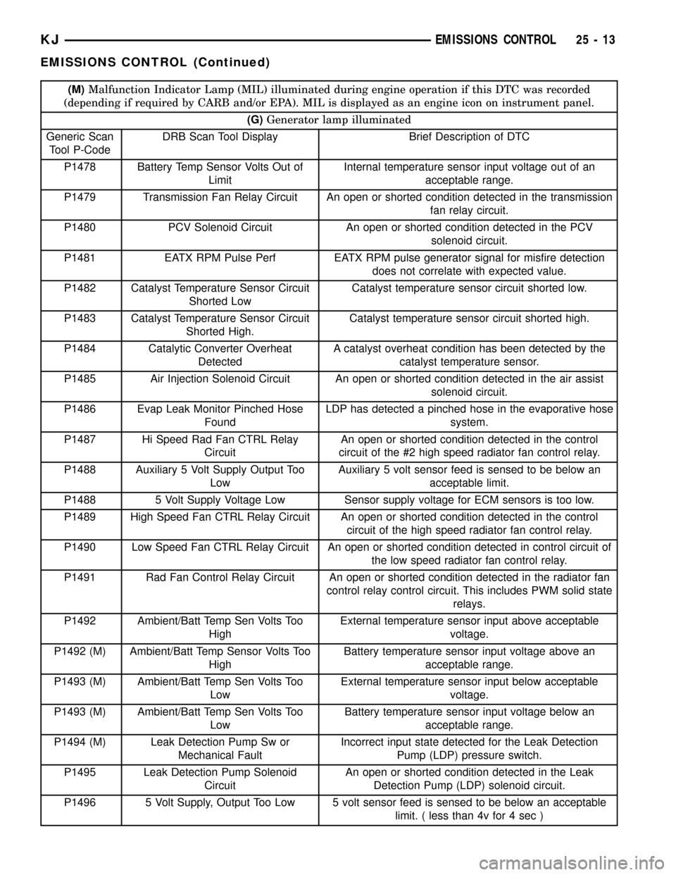
(M)Malfunction Indicator Lamp (MIL) illuminated during engine operation if this DTC was recorded
(depending if required by CARB and/or EPA). MIL is displayed as an engine icon on instrument panel.
(G)Generator lamp illuminated
Generic Scan
Tool P-CodeDRB Scan Tool Display Brief Description of DTC
P1478 Battery Temp Sensor Volts Out of
LimitInternal temperature sensor input voltage out of an
acceptable range.
P1479 Transmission Fan Relay Circuit An open or shorted condition detected in the transmission
fan relay circuit.
P1480 PCV Solenoid Circuit An open or shorted condition detected in the PCV
solenoid circuit.
P1481 EATX RPM Pulse Perf EATX RPM pulse generator signal for misfire detection
does not correlate with expected value.
P1482 Catalyst Temperature Sensor Circuit
Shorted LowCatalyst temperature sensor circuit shorted low.
P1483 Catalyst Temperature Sensor Circuit
Shorted High.Catalyst temperature sensor circuit shorted high.
P1484 Catalytic Converter Overheat
DetectedA catalyst overheat condition has been detected by the
catalyst temperature sensor.
P1485 Air Injection Solenoid Circuit An open or shorted condition detected in the air assist
solenoid circuit.
P1486 Evap Leak Monitor Pinched Hose
FoundLDP has detected a pinched hose in the evaporative hose
system.
P1487 Hi Speed Rad Fan CTRL Relay
CircuitAn open or shorted condition detected in the control
circuit of the #2 high speed radiator fan control relay.
P1488 Auxiliary 5 Volt Supply Output Too
LowAuxiliary 5 volt sensor feed is sensed to be below an
acceptable limit.
P1488 5 Volt Supply Voltage Low Sensor supply voltage for ECM sensors is too low.
P1489 High Speed Fan CTRL Relay Circuit An open or shorted condition detected in the control
circuit of the high speed radiator fan control relay.
P1490 Low Speed Fan CTRL Relay Circuit An open or shorted condition detected in control circuit of
the low speed radiator fan control relay.
P1491 Rad Fan Control Relay Circuit An open or shorted condition detected in the radiator fan
control relay control circuit. This includes PWM solid state
relays.
P1492 Ambient/Batt Temp Sen Volts Too
HighExternal temperature sensor input above acceptable
voltage.
P1492 (M) Ambient/Batt Temp Sensor Volts Too
HighBattery temperature sensor input voltage above an
acceptable range.
P1493 (M) Ambient/Batt Temp Sen Volts Too
LowExternal temperature sensor input below acceptable
voltage.
P1493 (M) Ambient/Batt Temp Sen Volts Too
LowBattery temperature sensor input voltage below an
acceptable range.
P1494 (M) Leak Detection Pump Sw or
Mechanical FaultIncorrect input state detected for the Leak Detection
Pump (LDP) pressure switch.
P1495 Leak Detection Pump Solenoid
CircuitAn open or shorted condition detected in the Leak
Detection Pump (LDP) solenoid circuit.
P1496 5 Volt Supply, Output Too Low 5 volt sensor feed is sensed to be below an acceptable
limit. ( less than 4v for 4 sec )
KJEMISSIONS CONTROL 25 - 13
EMISSIONS CONTROL (Continued)