2002 JEEP LIBERTY Tab 9
[x] Cancel search: Tab 9Page 1331 of 1803
INSPECTION
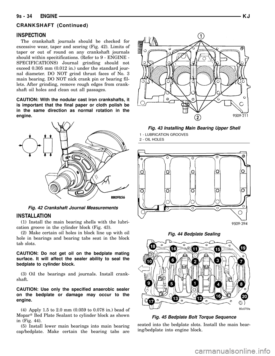
The crankshaft journals should be checked for
excessive wear, taper and scoring (Fig. 42). Limits of
taper or out of round on any crankshaft journals
should within specitifications. (Refer to 9 - ENGINE -
SPECIFICATIONS) Journal grinding should not
exceed 0.305 mm (0.012 in.) under the standard jour-
nal diameter. DO NOT grind thrust faces of No. 3
main bearing. DO NOT nick crank pin or bearing fil-
lets. After grinding, remove rough edges from crank-
shaft oil holes and clean out all passages.
CAUTION: With the nodular cast iron crankshafts, it
is important that the final paper or cloth polish be
in the same direction as normal rotation in the
engine.
INSTALLATION
(1) Install the main bearing shells with the lubri-
cation groove in the cylinder block (Fig. 43).
(2) Make certain oil holes in block line up with oil
hole in bearings and bearing tabs seat in the block
tab slots.
CAUTION: Do not get oil on the bedplate mating
surface. It will affect the sealer ability to seal the
bedplate to cylinder block.
(3) Oil the bearings and journals. Install crank-
shaft.
CAUTION: Use only the specified anaerobic sealer
on the bedplate or damage may occur to the
engine.
(4) Apply 1.5 to 2.0 mm (0.059 to 0.078 in.) bead of
MopartBed Plate Sealant to cylinder block as shown
in (Fig. 44).
(5) Install lower main bearings into main bearing
cap/bedplate. Make certain the bearing tabs areseated into the bedplate slots. Install the main bear-
ing/bedplate into engine block.
Fig. 42 Crankshaft Journal Measurements
Fig. 43 Installing Main Bearing Upper Shell
1 - LUBRICATION GROOVES
2 - OIL HOLES
Fig. 44 Bedplate Sealing
Fig. 45 Bedplate Bolt Torque Sequence
9s - 34 ENGINEKJ
CRANKSHAFT (Continued)
Page 1333 of 1803
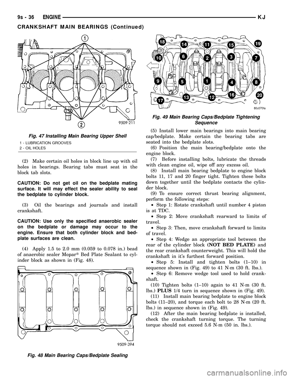
(2) Make certain oil holes in block line up with oil
holes in bearings. Bearing tabs must seat in the
block tab slots.
CAUTION: Do not get oil on the bedplate mating
surface. It will may effect the sealer ability to seal
the bedplate to cylinder block.
(3) Oil the bearings and journals and install
crankshaft.
CAUTION: Use only the specified anaerobic sealer
on the bedplate or damage may occur to the
engine. Ensure that both cylinder block and bed-
plate surfaces are clean.
(4) Apply 1.5 to 2.0 mm (0.059 to 0.078 in.) bead
of anaerobic sealer MopartBed Plate Sealant to cyl-
inder block as shown in (Fig. 48).(5) Install lower main bearings into main bearing
cap/bedplate. Make certain the bearing tabs are
seated into the bedplate slots.
(6) Position the main bearing/bedplate onto the
engine block.
(7) Before installing bolts, lubricate the threads
with clean engine oil, wipe off any excess oil.
(8) Install main bearing bedplate to engine block
bolts 11, 17 and 20 finger tight. Tighten these bolts
down together until the bedplate contacts the cylin-
der block.
(9) To ensure correct thrust bearing alignment,
perform the following steps:
²Step 1: Rotate crankshaft until number 4 piston
is at TDC.
²Step 2: Move crankshaft rearward to limits of
travel.
²Step 3: Then, move crankshaft forward to limits
of travel.
²Step 4: Wedge an appropriate tool between the
rear of the cylinder block(NOT BED PLATE)and
the rear crankshaft counterweight. This will hold the
crankshaft in it's furthest forward position.
²Step 5: Install and tighten bolts (1±10) in
sequence shown in (Fig. 49) to 41 N´m (30 ft. lbs.).
²Step 6: Remove wedge tool used to hold crank-
shaft.
(10) Tighten bolts (1±10) again to 41 N´m (30 ft.
lbs.)PLUS1/4 turn in sequence shown in (Fig. 49).
(11) Install main bearing bedplate to engine block
bolts (11±20), and torque each bolt to 28 N´m (20 ft.
lbs.) in sequence shown in (Fig. 49).
(12) After the main bearing bedplate is installed,
check the crankshaft turning torque. The turning
torque should not exceed 5.6 N´m (50 in. lbs.).
Fig. 47 Installing Main Bearing Upper Shell
1 - LUBRICATION GROOVES
2 - OIL HOLES
Fig. 48 Main Bearing Caps/Bedplate Sealing
Fig. 49 Main Bearing Caps/Bedplate Tightening
Sequence
9s - 36 ENGINEKJ
CRANKSHAFT MAIN BEARINGS (Continued)
Page 1344 of 1803
(6) Install oil pressure switch and connector. (Refer
to 9 - ENGINE/LUBRICATION/OIL PRESSURE
SENSOR/SWITCH - INSTALLATION)
OIL
STANDARD PROCEDURE
ENGINE OIL LEVEL CHECK
The best time to check engine oil level is after it
has sat overnight, or if the engine has been running,
allow the engine to be shut off for at least 5 minutes
before checking oil level.
Checking the oil while the vehicle is on level
ground will improve the accuracy of the oil level
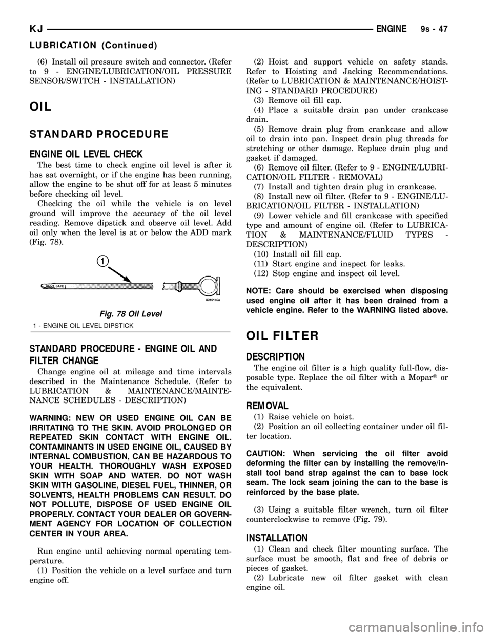
reading. Remove dipstick and observe oil level. Add
oil only when the level is at or below the ADD mark
(Fig. 78).
STANDARD PROCEDURE - ENGINE OIL AND
FILTER CHANGE
Change engine oil at mileage and time intervals
described in the Maintenance Schedule. (Refer to
LUBRICATION & MAINTENANCE/MAINTE-
NANCE SCHEDULES - DESCRIPTION)
WARNING: NEW OR USED ENGINE OIL CAN BE
IRRITATING TO THE SKIN. AVOID PROLONGED OR
REPEATED SKIN CONTACT WITH ENGINE OIL.
CONTAMINANTS IN USED ENGINE OIL, CAUSED BY
INTERNAL COMBUSTION, CAN BE HAZARDOUS TO
YOUR HEALTH. THOROUGHLY WASH EXPOSED
SKIN WITH SOAP AND WATER. DO NOT WASH
SKIN WITH GASOLINE, DIESEL FUEL, THINNER, OR
SOLVENTS, HEALTH PROBLEMS CAN RESULT. DO
NOT POLLUTE, DISPOSE OF USED ENGINE OIL
PROPERLY. CONTACT YOUR DEALER OR GOVERN-
MENT AGENCY FOR LOCATION OF COLLECTION
CENTER IN YOUR AREA.
Run engine until achieving normal operating tem-
perature.
(1) Position the vehicle on a level surface and turn
engine off.(2) Hoist and support vehicle on safety stands.
Refer to Hoisting and Jacking Recommendations.
(Refer to LUBRICATION & MAINTENANCE/HOIST-
ING - STANDARD PROCEDURE)
(3) Remove oil fill cap.
(4) Place a suitable drain pan under crankcase
drain.
(5) Remove drain plug from crankcase and allow
oil to drain into pan. Inspect drain plug threads for
stretching or other damage. Replace drain plug and
gasket if damaged.
(6) Remove oil filter. (Refer to 9 - ENGINE/LUBRI-
CATION/OIL FILTER - REMOVAL)
(7) Install and tighten drain plug in crankcase.
(8) Install new oil filter. (Refer to 9 - ENGINE/LU-
BRICATION/OIL FILTER - INSTALLATION)
(9) Lower vehicle and fill crankcase with specified
type and amount of engine oil. (Refer to LUBRICA-
TION & MAINTENANCE/FLUID TYPES -
DESCRIPTION)
(10) Install oil fill cap.
(11) Start engine and inspect for leaks.
(12) Stop engine and inspect oil level.
NOTE: Care should be exercised when disposing
used engine oil after it has been drained from a
vehicle engine. Refer to the WARNING listed above.
OIL FILTER
DESCRIPTION
The engine oil filter is a high quality full-flow, dis-
posable type. Replace the oil filter with a Mopartor
the equivalent.
REMOVAL
(1) Raise vehicle on hoist.
(2) Position an oil collecting container under oil fil-
ter location.
CAUTION: When servicing the oil filter avoid
deforming the filter can by installing the remove/in-
stall tool band strap against the can to base lock
seam. The lock seam joining the can to the base is
reinforced by the base plate.
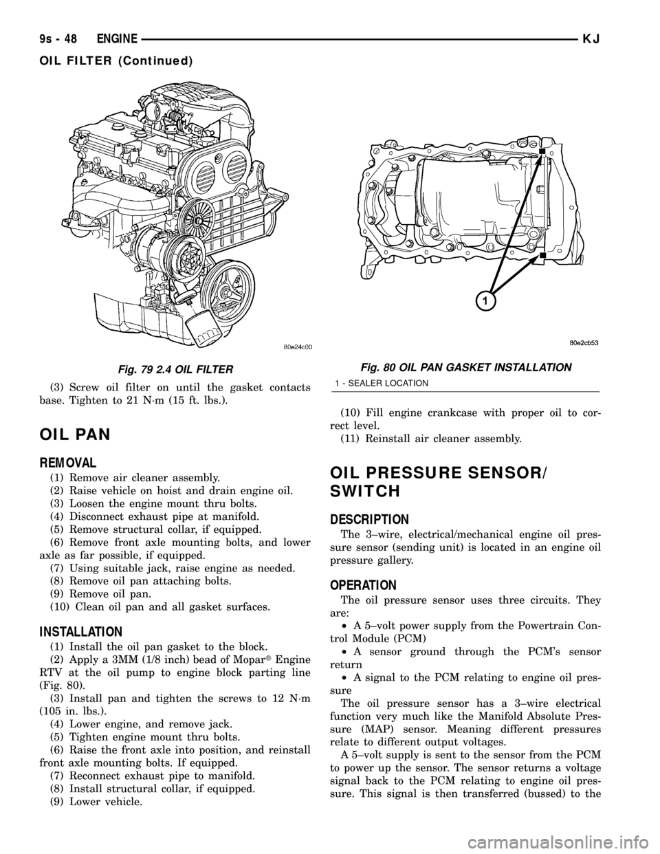
(3) Using a suitable filter wrench, turn oil filter
counterclockwise to remove (Fig. 79).
INSTALLATION
(1) Clean and check filter mounting surface. The
surface must be smooth, flat and free of debris or
pieces of gasket.
(2) Lubricate new oil filter gasket with clean
engine oil.
Fig. 78 Oil Level
1 - ENGINE OIL LEVEL DIPSTICK
KJENGINE9s-47
LUBRICATION (Continued)
Page 1345 of 1803
(3) Screw oil filter on until the gasket contacts
base. Tighten to 21 N´m (15 ft. lbs.).
OIL PAN
REMOVAL
(1) Remove air cleaner assembly.
(2) Raise vehicle on hoist and drain engine oil.
(3) Loosen the engine mount thru bolts.
(4) Disconnect exhaust pipe at manifold.
(5) Remove structural collar, if equipped.
(6) Remove front axle mounting bolts, and lower
axle as far possible, if equipped.
(7) Using suitable jack, raise engine as needed.
(8) Remove oil pan attaching bolts.
(9) Remove oil pan.
(10) Clean oil pan and all gasket surfaces.
INSTALLATION
(1) Install the oil pan gasket to the block.
(2) Apply a 3MM (1/8 inch) bead of MopartEngine
RTV at the oil pump to engine block parting line
(Fig. 80).
(3) Install pan and tighten the screws to 12 N´m
(105 in. lbs.).
(4) Lower engine, and remove jack.
(5) Tighten engine mount thru bolts.
(6) Raise the front axle into position, and reinstall
front axle mounting bolts. If equipped.
(7) Reconnect exhaust pipe to manifold.
(8) Install structural collar, if equipped.
(9) Lower vehicle.(10) Fill engine crankcase with proper oil to cor-
rect level.
(11) Reinstall air cleaner assembly.
OIL PRESSURE SENSOR/
SWITCH
DESCRIPTION
The 3±wire, electrical/mechanical engine oil pres-
sure sensor (sending unit) is located in an engine oil
pressure gallery.
OPERATION
The oil pressure sensor uses three circuits. They
are:
²A 5±volt power supply from the Powertrain Con-
trol Module (PCM)
²A sensor ground through the PCM's sensor
return
²A signal to the PCM relating to engine oil pres-
sure
The oil pressure sensor has a 3±wire electrical
function very much like the Manifold Absolute Pres-
sure (MAP) sensor. Meaning different pressures
relate to different output voltages.
A 5±volt supply is sent to the sensor from the PCM
to power up the sensor. The sensor returns a voltage
signal back to the PCM relating to engine oil pres-
sure. This signal is then transferred (bussed) to the
Fig. 79 2.4 OIL FILTERFig. 80 OIL PAN GASKET INSTALLATION
1 - SEALER LOCATION
9s - 48 ENGINEKJ
OIL FILTER (Continued)
Page 1346 of 1803
instrument panel on either a CCD or PCI bus circuit
(depending on vehicle line) to operate the oil pressure
gauge and the check gauges lamp. Ground for the
sensor is provided by the PCM through a low-noise
sensor return.
OIL PUMP
REMOVAL
(1) Disconnect negative cable from battery.
(2) Remove timing belt. (Refer to 9 - ENGINE/
VALVE TIMING/TIMING BELT/CHAIN AND
SPROCKETS - REMOVAL)
(3) Remove timing belt rear cover. (Refer to 9 -
ENGINE/VALVE TIMING/TIMING BELT / CHAIN
COVER(S) - REMOVAL)
(4) Remove oil pan. (Refer to 9 - ENGINE/LUBRI-
CATION/OIL PAN - REMOVAL)
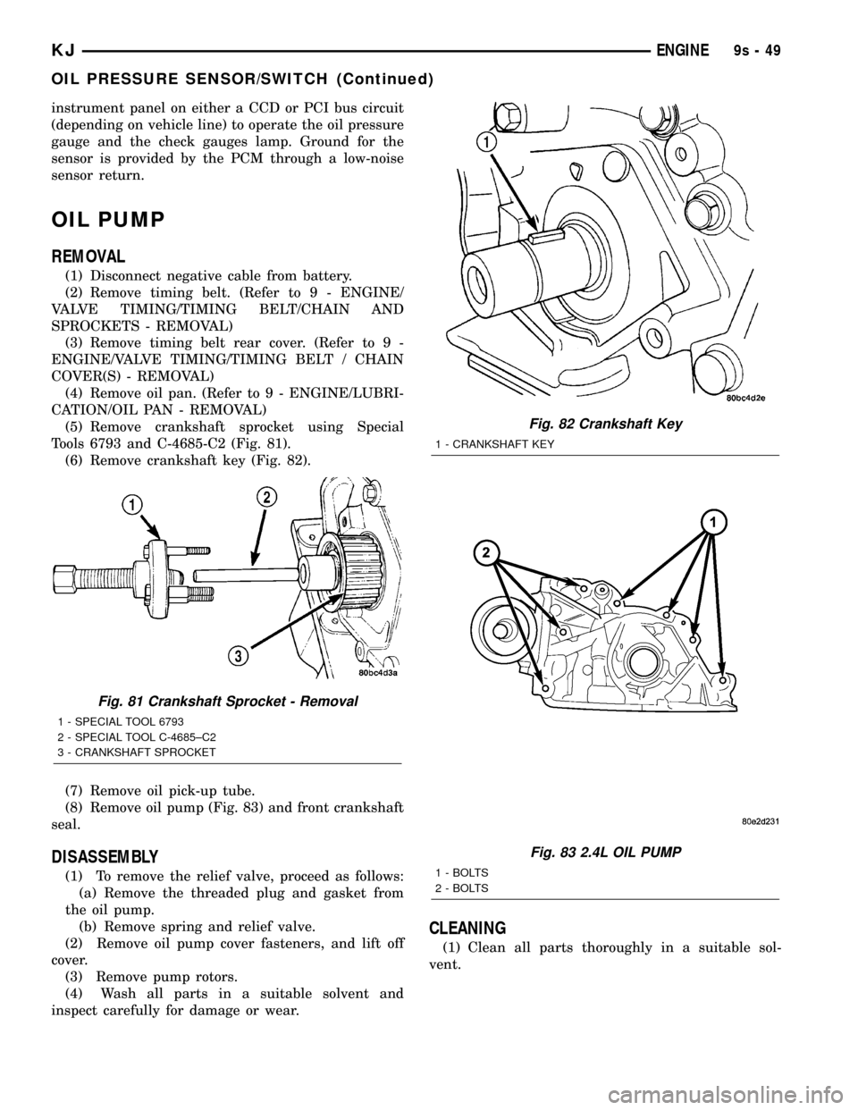
(5) Remove crankshaft sprocket using Special
Tools 6793 and C-4685-C2 (Fig. 81).
(6) Remove crankshaft key (Fig. 82).
(7) Remove oil pick-up tube.
(8) Remove oil pump (Fig. 83) and front crankshaft
seal.
DISASSEMBLY
(1) To remove the relief valve, proceed as follows:
(a) Remove the threaded plug and gasket from
the oil pump.
(b) Remove spring and relief valve.
(2) Remove oil pump cover fasteners, and lift off
cover.
(3) Remove pump rotors.
(4) Wash all parts in a suitable solvent and
inspect carefully for damage or wear.
CLEANING
(1) Clean all parts thoroughly in a suitable sol-
vent.
Fig. 81 Crankshaft Sprocket - Removal
1 - SPECIAL TOOL 6793
2 - SPECIAL TOOL C-4685±C2
3 - CRANKSHAFT SPROCKET
Fig. 82 Crankshaft Key
1 - CRANKSHAFT KEY
Fig. 83 2.4L OIL PUMP
1 - BOLTS
2 - BOLTS
KJENGINE9s-49
OIL PRESSURE SENSOR/SWITCH (Continued)
Page 1352 of 1803
TIMING BELT AND
SPROCKET(S)
REMOVAL
REMOVAL - TIMING BELT
(1) Remove air cleaner upper cover, housing, and
clean air tube.
(2) Raise vehicle on hoist.
(3) Remove accessory drive belts. (Refer to 7 -
COOLING/ACCESSORY DRIVE/BELT TENSION-
ERS - REMOVAL)
(4) Remove crankshaft vibration damper. (Refer to
9 - ENGINE/ENGINE BLOCK/VIBRATION
DAMPER - REMOVAL)
(5) Remove air conditioner/generator belt tensioner
and pulley assembly. (Refer to 7 - COOLING/ACCES-
SORY DRIVE/BELT TENSIONERS - REMOVAL)
(6) Remove timing belt lower front cover bolts and
remove cover. (Refer to 9 - ENGINE/VALVE TIMING/
TIMING BELT / CHAIN COVER(S) - REMOVAL)
(7) Lower vehicle.
(8) Remove bolts attaching timing belt upper front
cover and remove cover. (Refer to 9 - ENGINE/
VALVE TIMING/TIMING BELT / CHAIN COVER(S)
- REMOVAL)
CAUTION: When aligning crankshaft and camshaft
timing marks always rotate engine from crankshaft.
Camshaft should not be rotated after timing belt is
removed. Damage to valve components may occur.
Always align timing marks before removing timing
belt.
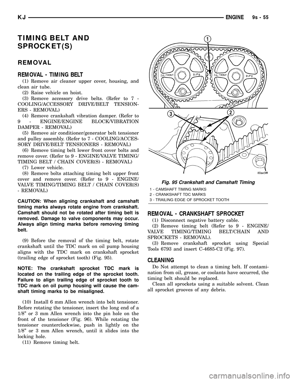
(9) Before the removal of the timing belt, rotate
crankshaft until the TDC mark on oil pump housing
aligns with the TDC mark on crankshaft sprocket
(trailing edge of sprocket tooth) (Fig. 95).
NOTE: The crankshaft sprocket TDC mark is
located on the trailing edge of the sprocket tooth.
Failure to align trailing edge of sprocket tooth to
TDC mark on oil pump housing will cause the cam-
shaft timing marks to be misaligned.
(10) Install 6 mm Allen wrench into belt tensioner.
Before rotating the tensioner, insert the long end of a
1/8º or 3 mm Allen wrench into the pin hole on the
front of the tensioner (Fig. 96). While rotating the
tensioner counterclockwise, push in lightly on the
1/8º or 3 mm Allen wrench, until it slides into the
locking hole.
(11) Remove timing belt.
REMOVAL - CRANKSHAFT SPROCKET
(1) Disconnect negative battery cable.
(2) Remove timing belt (Refer to 9 - ENGINE/
VALVE TIMING/TIMING BELT/CHAIN AND
SPROCKETS - REMOVAL).
(3) Remove crankshaft sprocket using Special
Tools 6793 and insert C-4685-C2 (Fig. 97).
CLEANING
Do Not attempt to clean a timing belt. If contami-
nation from oil, grease, or coolants have occurred, the
timing belt should be replaced.
Clean all sprockets using a suitable solvent. Clean
all sprocket grooves of any debris.
Fig. 95 Crankshaft and Camshaft Timing
1 - CAMSHAFT TIMING MARKS
2 - CRANKSHAFT TDC MARKS
3 - TRAILING EDGE OF SPROCKET TOOTH
KJENGINE9s-55
Page 1358 of 1803
INSTALLATION
BALANCE SHAFT TIMING
BALANCE SHAFT INSTALLATION
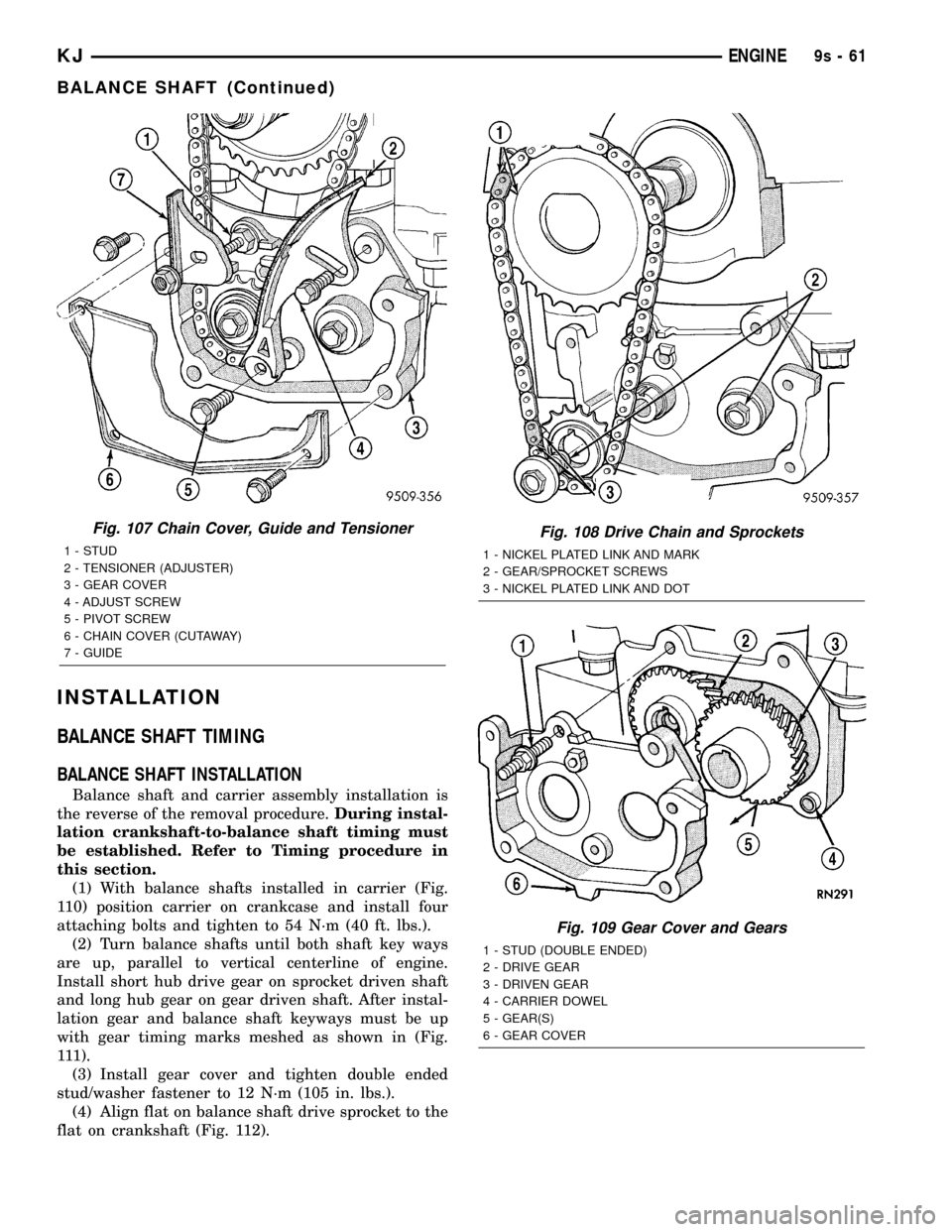
Balance shaft and carrier assembly installation is
the reverse of the removal procedure.During instal-
lation crankshaft-to-balance shaft timing must
be established. Refer to Timing procedure in
this section.
(1) With balance shafts installed in carrier (Fig.
110) position carrier on crankcase and install four
attaching bolts and tighten to 54 N´m (40 ft. lbs.).
(2) Turn balance shafts until both shaft key ways
are up, parallel to vertical centerline of engine.
Install short hub drive gear on sprocket driven shaft
and long hub gear on gear driven shaft. After instal-
lation gear and balance shaft keyways must be up
with gear timing marks meshed as shown in (Fig.
111).
(3) Install gear cover and tighten double ended
stud/washer fastener to 12 N´m (105 in. lbs.).
(4) Align flat on balance shaft drive sprocket to the
flat on crankshaft (Fig. 112).
Fig. 107 Chain Cover, Guide and Tensioner
1 - STUD
2 - TENSIONER (ADJUSTER)
3 - GEAR COVER
4 - ADJUST SCREW
5 - PIVOT SCREW
6 - CHAIN COVER (CUTAWAY)
7 - GUIDE
Fig. 108 Drive Chain and Sprockets
1 - NICKEL PLATED LINK AND MARK
2 - GEAR/SPROCKET SCREWS
3 - NICKEL PLATED LINK AND DOT
Fig. 109 Gear Cover and Gears
1 - STUD (DOUBLE ENDED)
2 - DRIVE GEAR
3 - DRIVEN GEAR
4 - CARRIER DOWEL
5 - GEAR(S)
6 - GEAR COVER
KJENGINE9s-61
BALANCE SHAFT (Continued)
Page 1360 of 1803
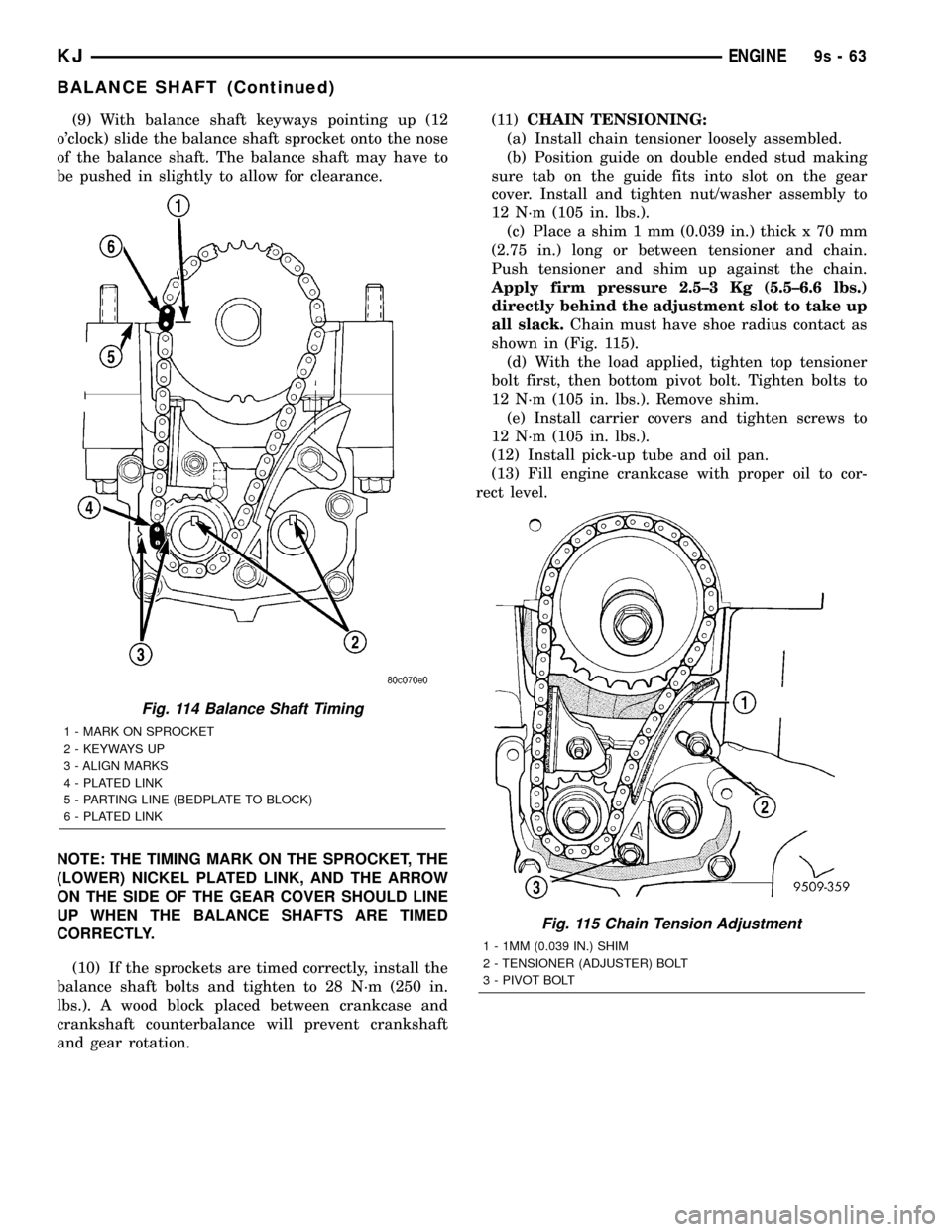
(9) With balance shaft keyways pointing up (12
o'clock) slide the balance shaft sprocket onto the nose
of the balance shaft. The balance shaft may have to
be pushed in slightly to allow for clearance.
NOTE: THE TIMING MARK ON THE SPROCKET, THE
(LOWER) NICKEL PLATED LINK, AND THE ARROW
ON THE SIDE OF THE GEAR COVER SHOULD LINE
UP WHEN THE BALANCE SHAFTS ARE TIMED
CORRECTLY.
(10) If the sprockets are timed correctly, install the
balance shaft bolts and tighten to 28 N´m (250 in.
lbs.). A wood block placed between crankcase and
crankshaft counterbalance will prevent crankshaft
and gear rotation.(11)CHAIN TENSIONING:
(a) Install chain tensioner loosely assembled.
(b) Position guide on double ended stud making
sure tab on the guide fits into slot on the gear
cover. Install and tighten nut/washer assembly to
12 N´m (105 in. lbs.).
(c) Place a shim 1 mm (0.039 in.) thick x 70 mm
(2.75 in.) long or between tensioner and chain.
Push tensioner and shim up against the chain.
Apply firm pressure 2.5±3 Kg (5.5±6.6 lbs.)
directly behind the adjustment slot to take up
all slack.Chain must have shoe radius contact as
shown in (Fig. 115).
(d) With the load applied, tighten top tensioner
bolt first, then bottom pivot bolt. Tighten bolts to
12 N´m (105 in. lbs.). Remove shim.
(e) Install carrier covers and tighten screws to
12 N´m (105 in. lbs.).
(12) Install pick-up tube and oil pan.
(13) Fill engine crankcase with proper oil to cor-
rect level.
Fig. 114 Balance Shaft Timing
1 - MARK ON SPROCKET
2 - KEYWAYS UP
3 - ALIGN MARKS
4 - PLATED LINK
5 - PARTING LINE (BEDPLATE TO BLOCK)
6 - PLATED LINK
Fig. 115 Chain Tension Adjustment
1 - 1MM (0.039 IN.) SHIM
2 - TENSIONER (ADJUSTER) BOLT
3 - PIVOT BOLT
KJENGINE9s-63
BALANCE SHAFT (Continued)