2002 JEEP LIBERTY Tab 9
[x] Cancel search: Tab 9Page 1251 of 1803
NOTE: Check for sharp edges on the keeper
grooves. Remove any burrs from the valve stem
before removing the valve from the cylinder head.
(7) Remove the valve from the cylinder head.
NOTE: The valve stem seals are common between
intake and exhaust.
(8) Remove the valve stem seal. Mark the valve for
proper installation.
TESTING VALVE SPRINGS
NOTE: Whenever the valves are removed from the
cylinder head it is recommended that the valve
springs be inspected and tested for reuse.
Inspect the valve springs for physical signs of wear
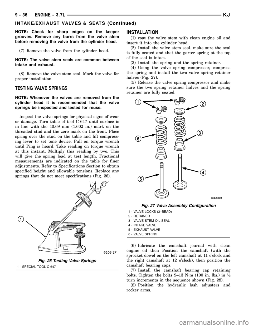
or damage. Turn table of tool C-647 until surface is
in line with the 40.69 mm (1.602 in.) mark on the
threaded stud and the zero mark on the front. Place
spring over the stud on the table and lift compress-
ing lever to set tone device. Pull on torque wrench
until Ping is heard. Take reading on torque wrench
at this instant. Multiply this reading by two. This
will give the spring load at test length. Fractional
measurements are indicated on the table for finer
adjustments. Refer to Specifications Section to obtain
specified height and allowable tensions. Replace any
springs that do not meet specifications (Fig. 26).
INSTALLATION
(1) coat the valve stem with clean engine oil and
insert it into the cylinder head.
(2) Install the valve stem seal. make sure the seal
is fully seated and that the garter spring at the top
of the seal is intact.
(3) Install the spring and the spring retainer.
(4) Using the valve spring compressor, compress
the spring and install the two valve spring retainer
halves (Fig. 27).
(5) Release the valve spring compressor and make
sure the two spring retainer halves and the spring
retainer are fully seated.
(6) lubricate the camshaft journal with clean
engine oil then Position the camshaft (with the
sprocket dowel on the left camshaft at 11 o'clock and
the right camshaft at 12 o'clock), then position the
camshaft bearing caps.
(7) Install the camshaft bearing cap retaining
bolts. Tighten the bolts 9±13 N´m (100 in. lbs.) in ó
turn increments in the sequence shown (Fig. 28).
(8) Position the hydraulic lash adjusters and
rocker arms.
Fig. 26 Testing Valve Springs
1 - SPECIAL TOOL C-647
Fig. 27 Valve Assembly Configuration
1 - VALVE LOCKS (3±BEAD)
2 - RETAINER
3 - VALVE STEM OIL SEAL
4 - INTAKE VALVE
5 - EXHAUST VALVE
6 - VALVE SPRING
9 - 36 ENGINE - 3.7LKJ
INTAKE/EXHAUST VALVES & SEATS (Continued)
Page 1255 of 1803
Once the block has been completely cleaned, apply
Loctite PST pipe sealant with Teflon 592 to the
threads of the front and rear oil galley plugs. Tighten
the plugs to 34 N´m (25 ft. lbs.) torque.
INSPECTION
(1) It is mandatory to use a dial bore gauge to
measure each cylinder bore diameter. To correctly
select the proper size piston, a cylinder bore gauge,
capable of reading in 0.003 mm (.0001 in.) INCRE-
MENTS is required. If a bore gauge is not available,
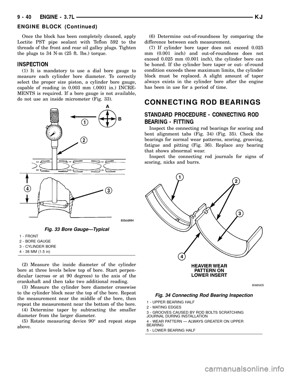
do not use an inside micrometer (Fig. 33).
(2) Measure the inside diameter of the cylinder
bore at three levels below top of bore. Start perpen-
dicular (across or at 90 degrees) to the axis of the
crankshaft and then take two additional reading.
(3) Measure the cylinder bore diameter crosswise
to the cylinder block near the top of the bore. Repeat
the measurement near the middle of the bore, then
repeat the measurement near the bottom of the bore.
(4) Determine taper by subtracting the smaller
diameter from the larger diameter.
(5) Rotate measuring device 90É and repeat steps
above.(6) Determine out-of-roundness by comparing the
difference between each measurement.
(7) If cylinder bore taper does not exceed 0.025
mm (0.001 inch) and out-of-roundness does not
exceed 0.025 mm (0.001 inch), the cylinder bore can
be honed. If the cylinder bore taper or out- of-round
condition exceeds these maximum limits, the cylinder
block must be replaced. A slight amount of taper
always exists in the cylinder bore after the engine
has been in use for a period of time.
CONNECTING ROD BEARINGS
STANDARD PROCEDURE - CONNECTING ROD
BEARING - FITTING
Inspect the connecting rod bearings for scoring and
bent alignment tabs (Fig. 34) (Fig. 35). Check the
bearings for normal wear patterns, scoring, grooving,
fatigue and pitting (Fig. 36). Replace any bearing
that shows abnormal wear.
Inspect the connecting rod journals for signs of
scoring, nicks and burrs.
Fig. 33 Bore GaugeÐTypical
1 - FRONT
2 - BORE GAUGE
3 - CYLINDER BORE
4 - 38 MM (1.5 in)
Fig. 34 Connecting Rod Bearing Inspection
1 - UPPER BEARING HALF
2 - MATING EDGES
3 - GROOVES CAUSED BY ROD BOLTS SCRATCHING
JOURNAL DURING INSTALLATION
4 - WEAR PATTERN Ð ALWAYS GREATER ON UPPER
BEARING
5 - LOWER BEARING HALF
9 - 40 ENGINE - 3.7LKJ
ENGINE BLOCK (Continued)
Page 1256 of 1803
Misaligned or bent connecting rods can cause
abnormal wear on pistons, piston rings, cylinder
walls, connecting rod bearings and crankshaft con-
necting rod journals. If wear patterns or damage to
any of these components indicate the probability of a
misaligned connecting rod, inspect it for correct rod
alignment. Replace misaligned, bent or twisted con-
necting rods.
(1) Wipe the oil from the connecting rod journal.
(2) Lubricate the upper bearing insert and install
in connecting rod.
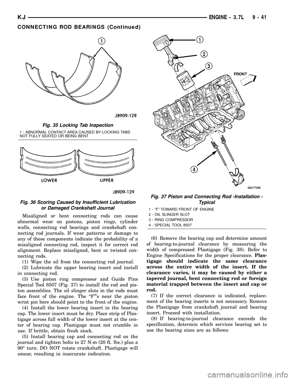
(3) Use piston ring compressor and Guide Pins
Special Tool 8507 (Fig. 37) to install the rod and pis-
ton assemblies. The oil slinger slots in the rods must
face front of the engine. The ªFº's near the piston
wrist pin bore should point to the front of the engine.
(4) Install the lower bearing insert in the bearing
cap. The lower insert must be dry. Place strip of Plas-
tigage across full width of the lower insert at the cen-
ter of bearing cap. Plastigage must not crumble in
use. If brittle, obtain fresh stock.
(5) Install bearing cap and connecting rod on the
journal and tighten bolts to 27 N´m (20 ft. lbs.) plus a
90É turn. DO NOT rotate crankshaft. Plastigage will
smear, resulting in inaccurate indication.(6) Remove the bearing cap and determine amount
of bearing-to-journal clearance by measuring the
width of compressed Plastigage (Fig. 38). Refer to
Engine Specifications for the proper clearance.Plas-
tigage should indicate the same clearance
across the entire width of the insert. If the
clearance varies, it may be caused by either a
tapered journal, bent connecting rod or foreign
material trapped between the insert and cap or
rod.
(7) If the correct clearance is indicated, replace-
ment of the bearing inserts is not necessary. Remove
the Plastigage from crankshaft journal and bearing
insert. Proceed with installation.
(8) If bearing-to-journal clearance exceeds the
specification, determin which services bearing set to
use the bearing sizes are as follows:
Fig. 35 Locking Tab Inspection
1 - ABNORMAL CONTACT AREA CAUSED BY LOCKING TABS
NOT FULLY SEATED OR BEING BENT
Fig. 36 Scoring Caused by Insufficient Lubrication
or Damaged Crankshaft Journal
Fig. 37 Piston and Connecting Rod -Installation -
Typical
1 - ªFº TOWARD FRONT OF ENGINE
2 - OIL SLINGER SLOT
3 - RING COMPRESSOR
4 - SPECIAL TOOL 8507
KJENGINE - 3.7L 9 - 41
CONNECTING ROD BEARINGS (Continued)
Page 1260 of 1803
CRANKSHAFT MAIN
BEARINGS
STANDARD PROCEDURE
MAIN BEARING - FITTING
SELECT FIT IDENTIFICATION
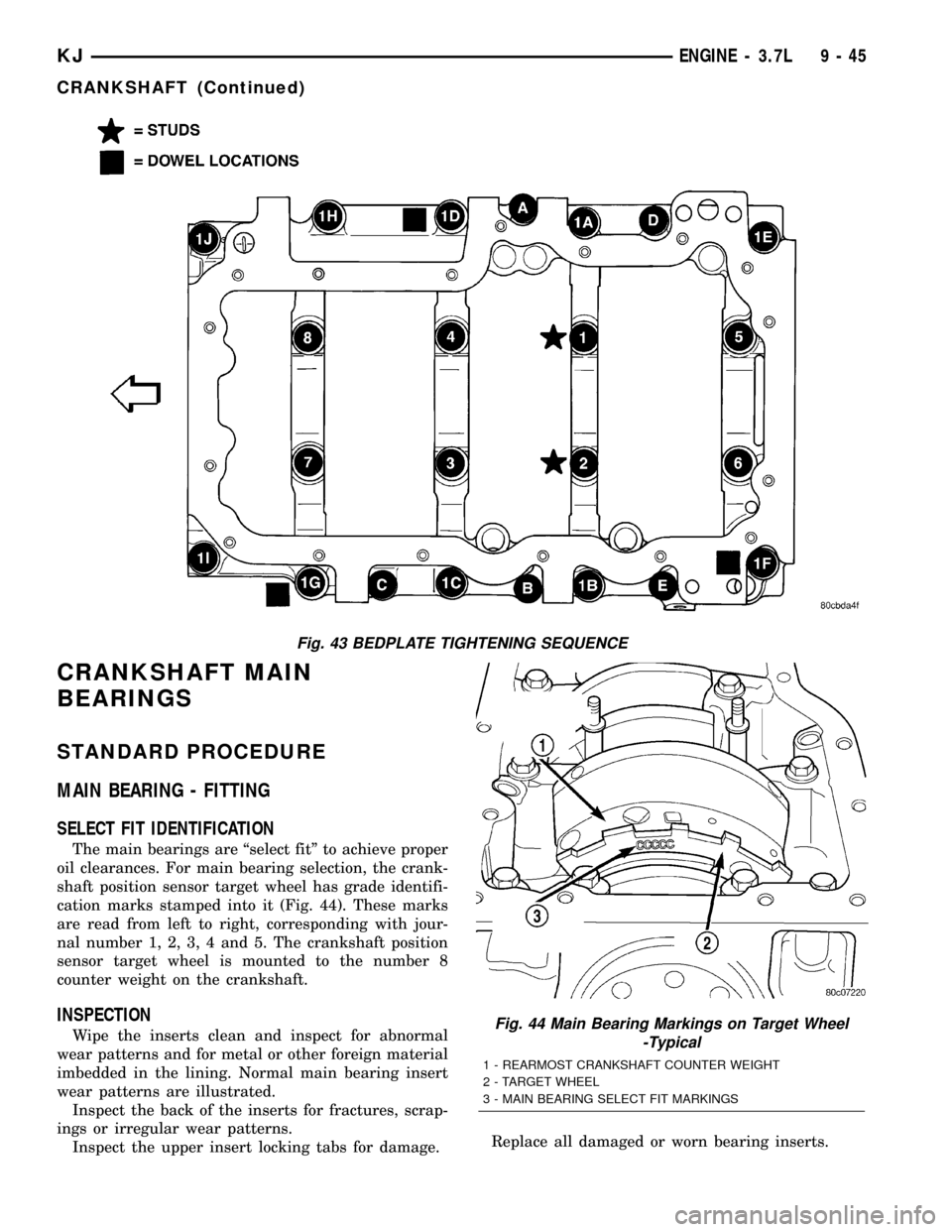
The main bearings are ªselect fitº to achieve proper
oil clearances. For main bearing selection, the crank-
shaft position sensor target wheel has grade identifi-
cation marks stamped into it (Fig. 44). These marks
are read from left to right, corresponding with jour-
nal number 1, 2, 3, 4 and 5. The crankshaft position
sensor target wheel is mounted to the number 8
counter weight on the crankshaft.
INSPECTION
Wipe the inserts clean and inspect for abnormal
wear patterns and for metal or other foreign material
imbedded in the lining. Normal main bearing insert
wear patterns are illustrated.
Inspect the back of the inserts for fractures, scrap-
ings or irregular wear patterns.
Inspect the upper insert locking tabs for damage.Replace all damaged or worn bearing inserts.
Fig. 43 BEDPLATE TIGHTENING SEQUENCE
Fig. 44 Main Bearing Markings on Target Wheel
-Typical
1 - REARMOST CRANKSHAFT COUNTER WEIGHT
2 - TARGET WHEEL
3 - MAIN BEARING SELECT FIT MARKINGS
KJENGINE - 3.7L 9 - 45
CRANKSHAFT (Continued)
Page 1264 of 1803
FLEX PLATE
REMOVAL
(1) Remove the transmission.
(2) Remove the bolts and flexplate.
INSTALLATION
(1) Position the flexplate onto the crankshaft and
install the bolts hand tight.
(2) Tighten the flexplate retaining bolts to 95 N´m
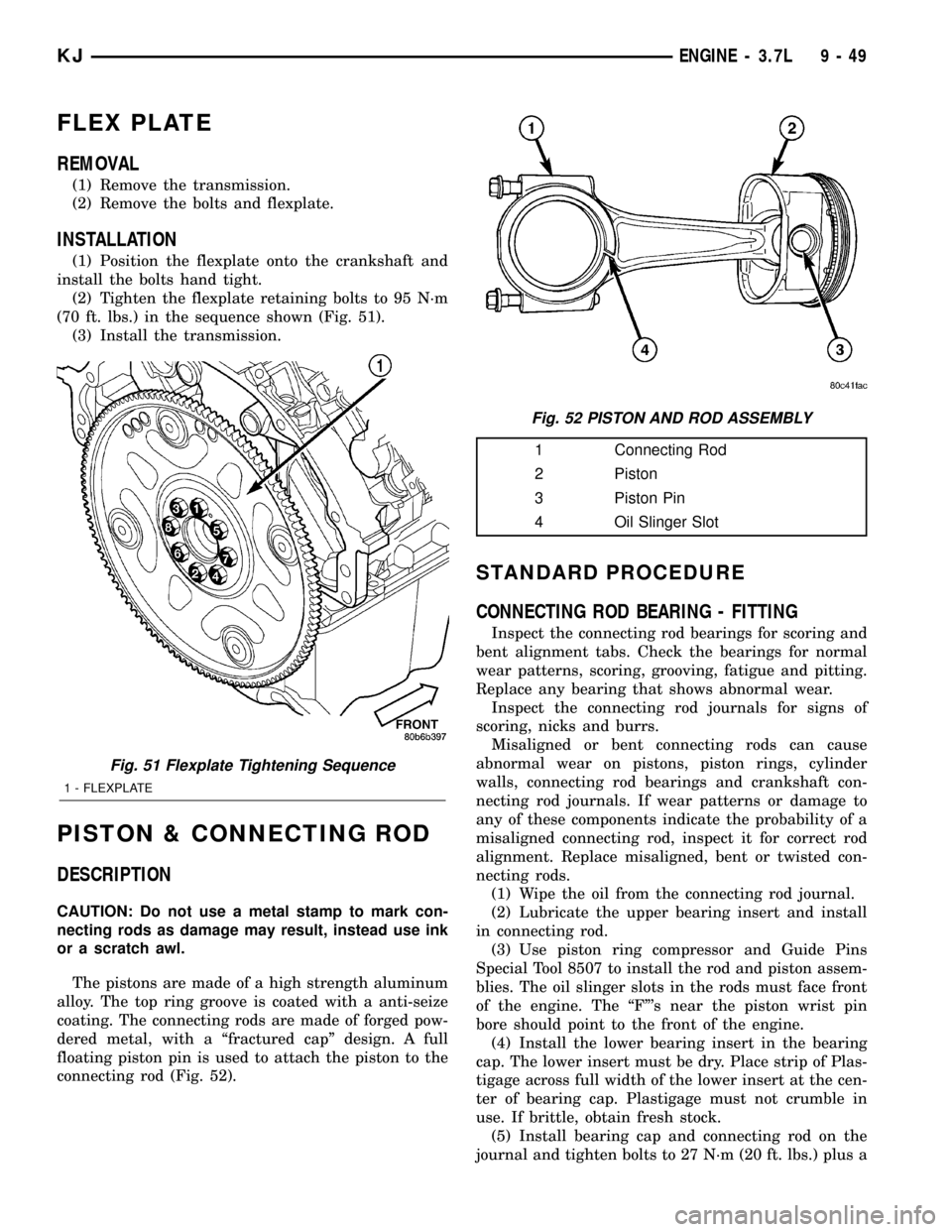
(70 ft. lbs.) in the sequence shown (Fig. 51).
(3) Install the transmission.
PISTON & CONNECTING ROD
DESCRIPTION
CAUTION: Do not use a metal stamp to mark con-
necting rods as damage may result, instead use ink
or a scratch awl.
The pistons are made of a high strength aluminum
alloy. The top ring groove is coated with a anti-seize
coating. The connecting rods are made of forged pow-
dered metal, with a ªfractured capº design. A full
floating piston pin is used to attach the piston to the
connecting rod (Fig. 52).
1 Connecting Rod
2 Piston
3 Piston Pin
4 Oil Slinger Slot
STANDARD PROCEDURE
CONNECTING ROD BEARING - FITTING
Inspect the connecting rod bearings for scoring and
bent alignment tabs. Check the bearings for normal
wear patterns, scoring, grooving, fatigue and pitting.
Replace any bearing that shows abnormal wear.
Inspect the connecting rod journals for signs of
scoring, nicks and burrs.
Misaligned or bent connecting rods can cause
abnormal wear on pistons, piston rings, cylinder
walls, connecting rod bearings and crankshaft con-
necting rod journals. If wear patterns or damage to
any of these components indicate the probability of a
misaligned connecting rod, inspect it for correct rod
alignment. Replace misaligned, bent or twisted con-
necting rods.
(1) Wipe the oil from the connecting rod journal.
(2) Lubricate the upper bearing insert and install
in connecting rod.
(3) Use piston ring compressor and Guide Pins
Special Tool 8507 to install the rod and piston assem-
blies. The oil slinger slots in the rods must face front
of the engine. The ªFº's near the piston wrist pin
bore should point to the front of the engine.
(4) Install the lower bearing insert in the bearing
cap. The lower insert must be dry. Place strip of Plas-
tigage across full width of the lower insert at the cen-
ter of bearing cap. Plastigage must not crumble in
use. If brittle, obtain fresh stock.
(5) Install bearing cap and connecting rod on the
journal and tighten bolts to 27 N´m (20 ft. lbs.) plus a
Fig. 51 Flexplate Tightening Sequence
1 - FLEXPLATE
Fig. 52 PISTON AND ROD ASSEMBLY
KJENGINE - 3.7L 9 - 49
Page 1266 of 1803
assemblies from the engine, rotate crankshaft so the
each connecting rod is centered in cylinder bore.
CAUTION: DO NOT use a number stamp or a punch
to mark connecting rods or caps, as damage to
connecting rods could occur
NOTE: Connecting rods and bearing caps are not
interchangeable and should be marked before
removing to ensure correct reassembly.
(4) Mark connecting rod and bearing cap positions
using a permanent ink marker or scribe tool.
CAUTION: Care must be taken not to damage the
fractured rod and cap joint face surfaces, as engine
damage may occur.
(5) Remove connecting rod cap. Install Special Tool
8507 Connecting Rod Guides into the connecting rod
being removed. Remove piston from cylinder bore.
Repeat this procedure for each piston being removed.
CAUTION: Care must be taken not to nick crank-
shaft journals, as engine damage may occur
(6) Immediately after piston and connecting rod
removal, install bearing cap on the mating connect-
ing rod to prevent damage to the fractured cap and
rod surfaces.
CLEANING
CAUTION: DO NOT use a wire wheel or other abra-
sive cleaning devise to clean the pistons or con-
necting rods. The pistons have a Moly coating, this
coating must not be damaged.
(1) Using a suitable cleaning solvent clean the pis-
tons in warm water and towel dry.
(2) Use a wood or plastic scraper to clean the ring
land grooves.
CAUTION: DO NOT remove the piston pin from the
piston and connecting rod assembly.
INSPECTION
Check the connecting rod journal for excessive
wear, taper and scoring (Refer to 9 - ENGINE/EN-
GINE BLOCK/CONNECTING ROD BEARINGS -
STANDARD PROCEDURE).
Check the connecting rod for signs of twist or bend-
ing.
Check the piston for taper and elliptical shape
before it is fitted into the cylinder bore (Refer to 9 -
ENGINE/ENGINE BLOCK/PISTON & CONNECT-
ING ROD - STANDARD PROCEDURE).
Check the piston for scoring, or scraping marks in
the piston skirts. Check the ring lands for cracks
and/or deterioration.
INSTALLATION
(1) Before installing piston and connecting rod
assemblies into the bore, install the piston rings.
(2) Immerse the piston head and rings in clean
engine oil. Position a ring compressor over the piston
and rings. Tighten ring compressor.Ensure posi-
tion of rings do not change during this opera-
tion.
(3) Position bearing onto connecting rod. Ensure
that tabs in bearing shell aligns with slots in con-
necting rod. Verify that parting line of bearing is
aligned with parting line of connecting rod.
(4) Lubricate bearing surface with clean engine oil.
(5) Install Special Tool 8507 Connecting Rod
Guides into connecting rod bolt threads (Fig. 55).
(6) The pistons are marked on the piston pin bore
surface with an raised ªFº indicating installation
position. This mark must be pointing toward the
front of engine on both cylinder banks. The connect-
ing rod oil slinger slot faces the front of the engine
(Fig. 56).
(7) Wipe cylinder bore clean and lubricate with
engine oil.
(8) Rotate crankshaft until connecting rod journal
is on the center of cylinder bore. Insert rod and pis-
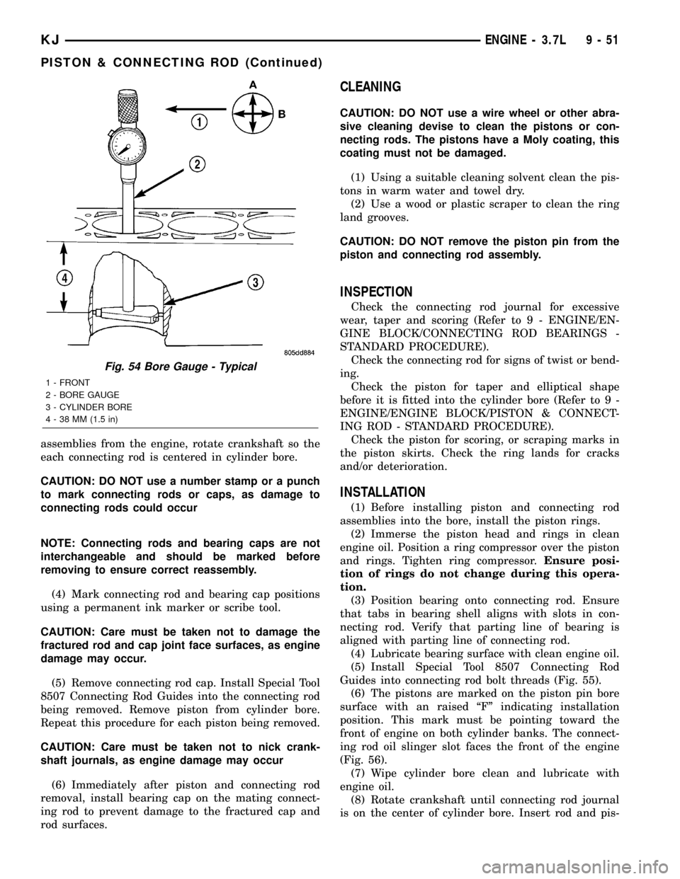
Fig. 54 Bore Gauge - Typical
1 - FRONT
2 - BORE GAUGE
3 - CYLINDER BORE
4 - 38 MM (1.5 in)
KJENGINE - 3.7L 9 - 51
PISTON & CONNECTING ROD (Continued)
Page 1271 of 1803
CAUTION: The structural cover must be held tightly
against both the engine and the transmission bell
housing during tightening sequence. Failure to do
so may cause damage to the cover.
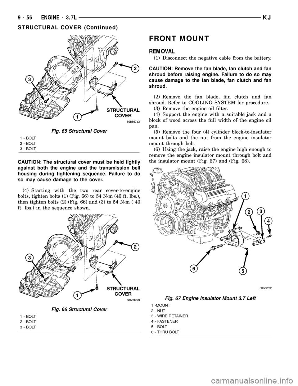
(4) Starting with the two rear cover-to-engine
bolts, tighten bolts (1) (Fig. 66) to 54 N´m (40 ft. lbs.),
then tighten bolts (2) (Fig. 66) and (3) to 54 N´m ( 40
ft. lbs.) in the sequence shown.
FRONT MOUNT
REMOVAL
(1) Disconnect the negative cable from the battery.
CAUTION: Remove the fan blade, fan clutch and fan
shroud before raising engine. Failure to do so may
cause damage to the fan blade, fan clutch and fan
shroud.
(2) Remove the fan blade, fan clutch and fan
shroud. Refer to COOLING SYSTEM for procedure.
(3) Remove the engine oil filter.
(4) Support the engine with a suitable jack and a
block of wood across the full width of the engine oil
pan.
(5) Remove the four (4) cylinder block-to-insulator
mount bolts and the nut from the engine insulator
mount through bolt.
(6) Using the jack, raise the engine high enough to
remove the engine insulator mount through bolt and
the insulator mount (Fig. 67) and (Fig. 68).
Fig. 65 Structural Cover
1 - BOLT
2 - BOLT
3 - BOLT
Fig. 66 Structural Cover
1 - BOLT
2 - BOLT
3 - BOLT
Fig. 67 Engine Insulator Mount 3.7 Left
1 -MOUNT
2 - NUT
3 - WIRE RETAINER
4 - FASTENER
5 - BOLT
6 - THRU BOLT
9 - 56 ENGINE - 3.7LKJ
STRUCTURAL COVER (Continued)
Page 1273 of 1803
OPERATION
Oil from the oil pan is pumped by a gerotor type oil
pump directly mounted to the crankshaft nose. Oil
pressure is controlled by a relief valve mounted
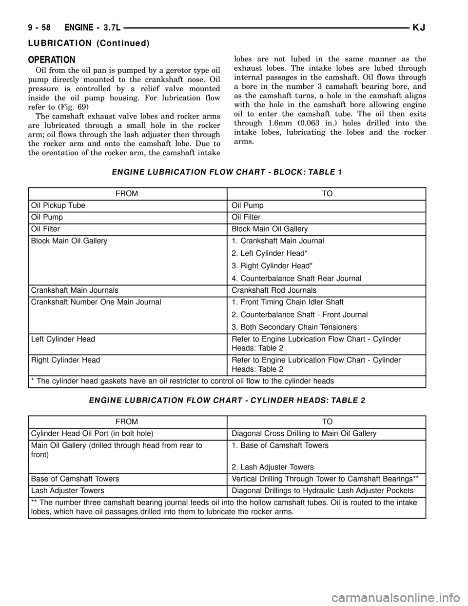
inside the oil pump housing. For lubrication flow
refer to (Fig. 69)
The camshaft exhaust valve lobes and rocker arms
are lubricated through a small hole in the rocker
arm; oil flows through the lash adjuster then through
the rocker arm and onto the camshaft lobe. Due to
the orentation of the rocker arm, the camshaft intakelobes are not lubed in the same manner as the
exhaust lobes. The intake lobes are lubed through
internal passages in the camshaft. Oil flows through
a bore in the number 3 camshaft bearing bore, and
as the camshaft turns, a hole in the camshaft aligns
with the hole in the camshaft bore allowing engine
oil to enter the camshaft tube. The oil then exits
through 1.6mm (0.063 in.) holes drilled into the
intake lobes, lubricating the lobes and the rocker
arms.
ENGINE LUBRICATION FLOW CHART - BLOCK: TABLE 1
FROM TO
Oil Pickup Tube Oil Pump
Oil Pump Oil Filter
Oil Filter Block Main Oil Gallery
Block Main Oil Gallery 1. Crankshaft Main Journal
2. Left Cylinder Head*
3. Right Cylinder Head*
4. Counterbalance Shaft Rear Journal
Crankshaft Main Journals Crankshaft Rod Journals
Crankshaft Number One Main Journal 1. Front Timing Chain Idler Shaft
2. Counterbalance Shaft - Front Journal
3. Both Secondary Chain Tensioners
Left Cylinder Head Refer to Engine Lubrication Flow Chart - Cylinder
Heads: Table 2
Right Cylinder Head Refer to Engine Lubrication Flow Chart - Cylinder
Heads: Table 2
* The cylinder head gaskets have an oil restricter to control oil flow to the cylinder heads
ENGINE LUBRICATION FLOW CHART - CYLINDER HEADS: TABLE 2
FROM TO
Cylinder Head Oil Port (in bolt hole) Diagonal Cross Drilling to Main Oil Gallery
Main Oil Gallery (drilled through head from rear to
front)1. Base of Camshaft Towers
2. Lash Adjuster Towers
Base of Camshaft Towers Vertical Drilling Through Tower to Camshaft Bearings**
Lash Adjuster Towers Diagonal Drillings to Hydraulic Lash Adjuster Pockets
** The number three camshaft bearing journal feeds oil into the hollow camshaft tubes. Oil is routed to the intake
lobes, which have oil passages drilled into them to lubricate the rocker arms.
9 - 58 ENGINE - 3.7LKJ
LUBRICATION (Continued)