2002 JEEP LIBERTY relay
[x] Cancel search: relayPage 1162 of 1803
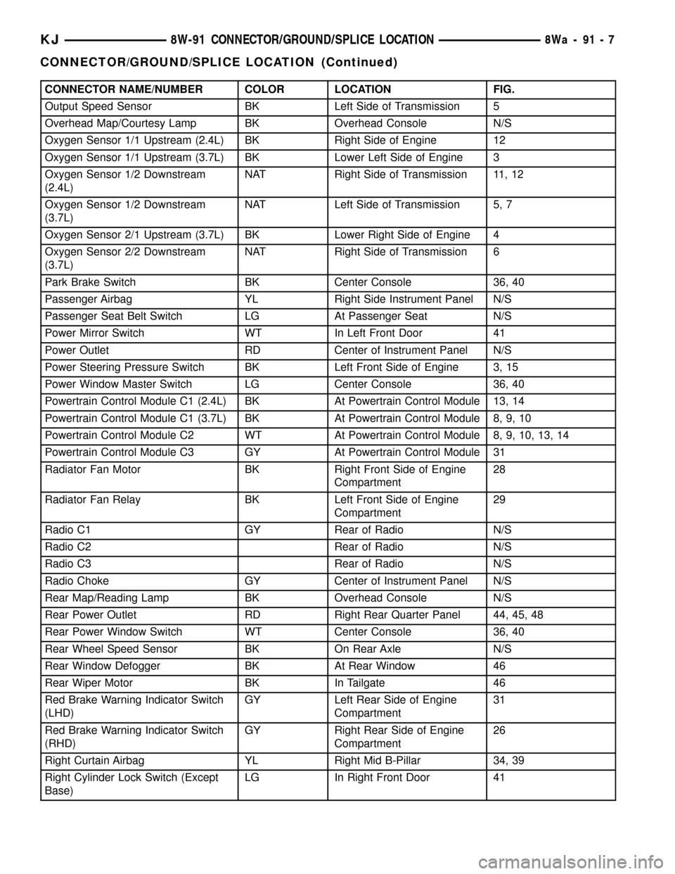
CONNECTOR NAME/NUMBER COLOR LOCATION FIG.
Output Speed Sensor BK Left Side of Transmission 5
Overhead Map/Courtesy Lamp BK Overhead Console N/S
Oxygen Sensor 1/1 Upstream (2.4L) BK Right Side of Engine 12
Oxygen Sensor 1/1 Upstream (3.7L) BK Lower Left Side of Engine 3
Oxygen Sensor 1/2 Downstream
(2.4L)NAT Right Side of Transmission 11, 12
Oxygen Sensor 1/2 Downstream
(3.7L)NAT Left Side of Transmission 5, 7
Oxygen Sensor 2/1 Upstream (3.7L) BK Lower Right Side of Engine 4
Oxygen Sensor 2/2 Downstream
(3.7L)NAT Right Side of Transmission 6
Park Brake Switch BK Center Console 36, 40
Passenger Airbag YL Right Side Instrument Panel N/S
Passenger Seat Belt Switch LG At Passenger Seat N/S
Power Mirror Switch WT In Left Front Door 41
Power Outlet RD Center of Instrument Panel N/S
Power Steering Pressure Switch BK Left Front Side of Engine 3, 15
Power Window Master Switch LG Center Console 36, 40
Powertrain Control Module C1 (2.4L) BK At Powertrain Control Module 13, 14
Powertrain Control Module C1 (3.7L) BK At Powertrain Control Module 8, 9, 10
Powertrain Control Module C2 WT At Powertrain Control Module 8, 9, 10, 13, 14
Powertrain Control Module C3 GY At Powertrain Control Module 31
Radiator Fan Motor BK Right Front Side of Engine
Compartment28
Radiator Fan Relay BK Left Front Side of Engine
Compartment29
Radio C1 GY Rear of Radio N/S
Radio C2 Rear of Radio N/S
Radio C3 Rear of Radio N/S
Radio Choke GY Center of Instrument Panel N/S
Rear Map/Reading Lamp BK Overhead Console N/S
Rear Power Outlet RD Right Rear Quarter Panel 44, 45, 48
Rear Power Window Switch WT Center Console 36, 40
Rear Wheel Speed Sensor BK On Rear Axle N/S
Rear Window Defogger BK At Rear Window 46
Rear Wiper Motor BK In Tailgate 46
Red Brake Warning Indicator Switch
(LHD)GY Left Rear Side of Engine
Compartment31
Red Brake Warning Indicator Switch
(RHD)GY Right Rear Side of Engine
Compartment26
Right Curtain Airbag YL Right Mid B-Pillar 34, 39
Right Cylinder Lock Switch (Except
Base)LG In Right Front Door 41
KJ8W-91 CONNECTOR/GROUND/SPLICE LOCATION8Wa-91-7
CONNECTOR/GROUND/SPLICE LOCATION (Continued)
Page 1164 of 1803
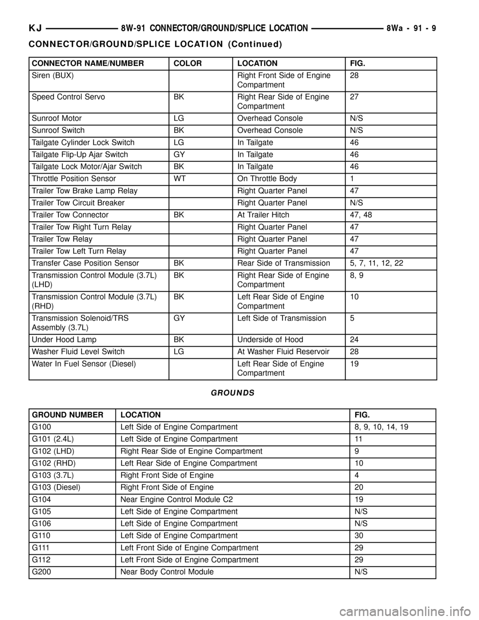
CONNECTOR NAME/NUMBER COLOR LOCATION FIG.
Siren (BUX) Right Front Side of Engine
Compartment28
Speed Control Servo BK Right Rear Side of Engine
Compartment27
Sunroof Motor LG Overhead Console N/S
Sunroof Switch BK Overhead Console N/S
Tailgate Cylinder Lock Switch LG In Tailgate 46
Tailgate Flip-Up Ajar Switch GY In Tailgate 46
Tailgate Lock Motor/Ajar Switch BK In Tailgate 46
Throttle Position Sensor WT On Throttle Body 1
Trailer Tow Brake Lamp Relay Right Quarter Panel 47
Trailer Tow Circuit Breaker Right Quarter Panel N/S
Trailer Tow Connector BK At Trailer Hitch 47, 48
Trailer Tow Right Turn Relay Right Quarter Panel 47
Trailer Tow Relay Right Quarter Panel 47
Trailer Tow Left Turn Relay Right Quarter Panel 47
Transfer Case Position Sensor BK Rear Side of Transmission 5, 7, 11, 12, 22
Transmission Control Module (3.7L)
(LHD)BK Right Rear Side of Engine
Compartment8, 9
Transmission Control Module (3.7L)
(RHD)BK Left Rear Side of Engine
Compartment10
Transmission Solenoid/TRS
Assembly (3.7L)GY Left Side of Transmission 5
Under Hood Lamp BK Underside of Hood 24
Washer Fluid Level Switch LG At Washer Fluid Reservoir 28
Water In Fuel Sensor (Diesel) Left Rear Side of Engine
Compartment19
GROUNDS
GROUND NUMBER LOCATION FIG.
G100 Left Side of Engine Compartment 8, 9, 10, 14, 19
G101 (2.4L) Left Side of Engine Compartment 11
G102 (LHD) Right Rear Side of Engine Compartment 9
G102 (RHD) Left Rear Side of Engine Compartment 10
G103 (3.7L) Right Front Side of Engine 4
G103 (Diesel) Right Front Side of Engine 20
G104 Near Engine Control Module C2 19
G105 Left Side of Engine Compartment N/S
G106 Left Side of Engine Compartment N/S
G110 Left Side of Engine Compartment 30
G111 Left Front Side of Engine Compartment 29
G112 Left Front Side of Engine Compartment 29
G200 Near Body Control Module N/S
KJ8W-91 CONNECTOR/GROUND/SPLICE LOCATION8Wa-91-9
CONNECTOR/GROUND/SPLICE LOCATION (Continued)
Page 1165 of 1803
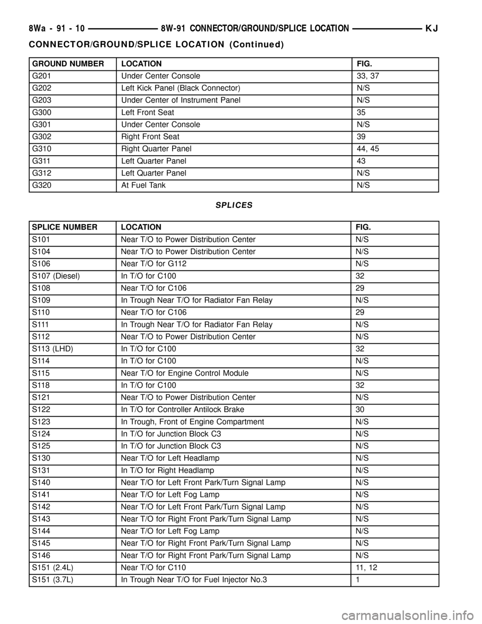
GROUND NUMBER LOCATION FIG.
G201 Under Center Console 33, 37
G202 Left Kick Panel (Black Connector) N/S
G203 Under Center of Instrument Panel N/S
G300 Left Front Seat 35
G301 Under Center Console N/S
G302 Right Front Seat 39
G310 Right Quarter Panel 44, 45
G311 Left Quarter Panel 43
G312 Left Quarter Panel N/S
G320 At Fuel Tank N/S
SPLICES
SPLICE NUMBER LOCATION FIG.
S101 Near T/O to Power Distribution Center N/S
S104 Near T/O to Power Distribution Center N/S
S106 Near T/O for G112 N/S
S107 (Diesel) In T/O for C100 32
S108 Near T/O for C106 29
S109 In Trough Near T/O for Radiator Fan Relay N/S
S110 Near T/O for C106 29
S111 In Trough Near T/O for Radiator Fan Relay N/S
S112 Near T/O to Power Distribution Center N/S
S113 (LHD) In T/O for C100 32
S114 In T/O for C100 N/S
S115 Near T/O for Engine Control Module N/S
S118 In T/O for C100 32
S121 Near T/O to Power Distribution Center N/S
S122 In T/O for Controller Antilock Brake 30
S123 In Trough, Front of Engine Compartment N/S
S124 In T/O for Junction Block C3 N/S
S125 In T/O for Junction Block C3 N/S
S130 Near T/O for Left Headlamp N/S
S131 In T/O for Right Headlamp N/S
S140 Near T/O for Left Front Park/Turn Signal Lamp N/S
S141 Near T/O for Left Fog Lamp N/S
S142 Near T/O for Left Front Park/Turn Signal Lamp N/S
S143 Near T/O for Right Front Park/Turn Signal Lamp N/S
S144 Near T/O for Left Fog Lamp N/S
S145 Near T/O for Right Front Park/Turn Signal Lamp N/S
S146 Near T/O for Right Front Park/Turn Signal Lamp N/S
S151 (2.4L) Near T/O for C110 11, 12
S151 (3.7L) In Trough Near T/O for Fuel Injector No.3 1
8Wa - 91 - 10 8W-91 CONNECTOR/GROUND/SPLICE LOCATIONKJ
CONNECTOR/GROUND/SPLICE LOCATION (Continued)
Page 1167 of 1803
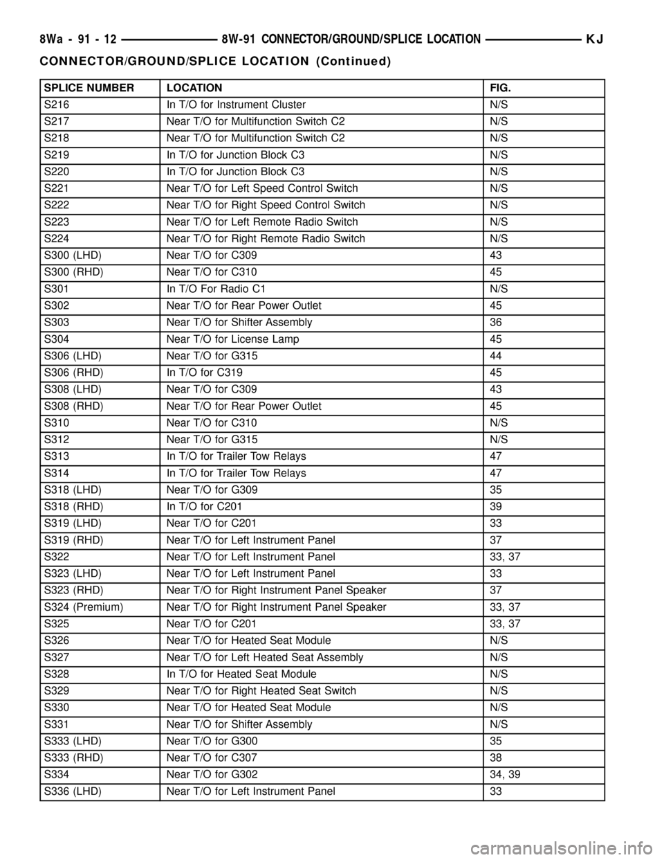
SPLICE NUMBER LOCATION FIG.
S216 In T/O for Instrument Cluster N/S
S217 Near T/O for Multifunction Switch C2 N/S
S218 Near T/O for Multifunction Switch C2 N/S
S219 In T/O for Junction Block C3 N/S
S220 In T/O for Junction Block C3 N/S
S221 Near T/O for Left Speed Control Switch N/S
S222 Near T/O for Right Speed Control Switch N/S
S223 Near T/O for Left Remote Radio Switch N/S
S224 Near T/O for Right Remote Radio Switch N/S
S300 (LHD) Near T/O for C309 43
S300 (RHD) Near T/O for C310 45
S301 In T/O For Radio C1 N/S
S302 Near T/O for Rear Power Outlet 45
S303 Near T/O for Shifter Assembly 36
S304 Near T/O for License Lamp 45
S306 (LHD) Near T/O for G315 44
S306 (RHD) In T/O for C319 45
S308 (LHD) Near T/O for C309 43
S308 (RHD) Near T/O for Rear Power Outlet 45
S310 Near T/O for C310 N/S
S312 Near T/O for G315 N/S
S313 In T/O for Trailer Tow Relays 47
S314 In T/O for Trailer Tow Relays 47
S318 (LHD) Near T/O for G309 35
S318 (RHD) In T/O for C201 39
S319 (LHD) Near T/O for C201 33
S319 (RHD) Near T/O for Left Instrument Panel 37
S322 Near T/O for Left Instrument Panel 33, 37
S323 (LHD) Near T/O for Left Instrument Panel 33
S323 (RHD) Near T/O for Right Instrument Panel Speaker 37
S324 (Premium) Near T/O for Right Instrument Panel Speaker 33, 37
S325 Near T/O for C201 33, 37
S326 Near T/O for Heated Seat Module N/S
S327 Near T/O for Left Heated Seat Assembly N/S
S328 In T/O for Heated Seat Module N/S
S329 Near T/O for Right Heated Seat Switch N/S
S330 Near T/O for Heated Seat Module N/S
S331 Near T/O for Shifter Assembly N/S
S333 (LHD) Near T/O for G300 35
S333 (RHD) Near T/O for C307 38
S334 Near T/O for G302 34, 39
S336 (LHD) Near T/O for Left Instrument Panel 33
8Wa - 91 - 12 8W-91 CONNECTOR/GROUND/SPLICE LOCATIONKJ
CONNECTOR/GROUND/SPLICE LOCATION (Continued)
Page 1168 of 1803
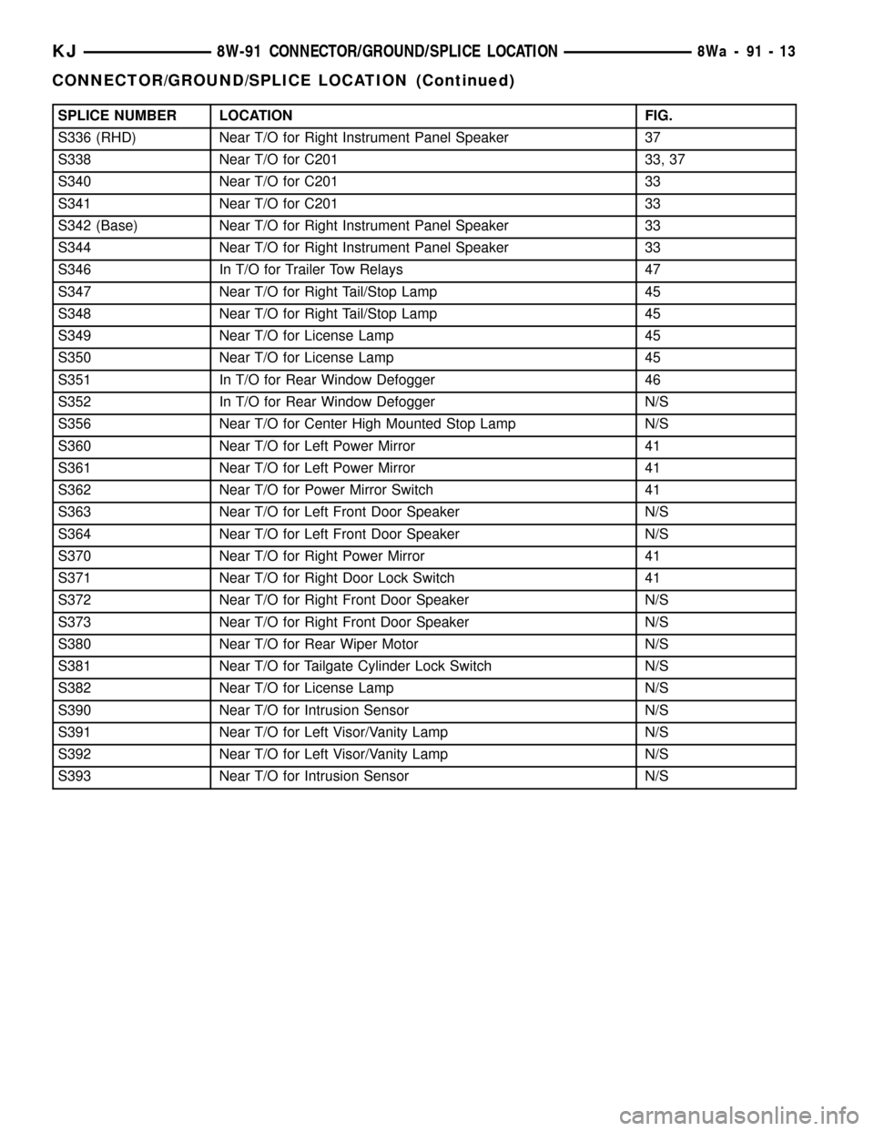
SPLICE NUMBER LOCATION FIG.
S336 (RHD) Near T/O for Right Instrument Panel Speaker 37
S338 Near T/O for C201 33, 37
S340 Near T/O for C201 33
S341 Near T/O for C201 33
S342 (Base) Near T/O for Right Instrument Panel Speaker 33
S344 Near T/O for Right Instrument Panel Speaker 33
S346 In T/O for Trailer Tow Relays 47
S347 Near T/O for Right Tail/Stop Lamp 45
S348 Near T/O for Right Tail/Stop Lamp 45
S349 Near T/O for License Lamp 45
S350 Near T/O for License Lamp 45
S351 In T/O for Rear Window Defogger 46
S352 In T/O for Rear Window Defogger N/S
S356 Near T/O for Center High Mounted Stop Lamp N/S
S360 Near T/O for Left Power Mirror 41
S361 Near T/O for Left Power Mirror 41
S362 Near T/O for Power Mirror Switch 41
S363 Near T/O for Left Front Door Speaker N/S
S364 Near T/O for Left Front Door Speaker N/S
S370 Near T/O for Right Power Mirror 41
S371 Near T/O for Right Door Lock Switch 41
S372 Near T/O for Right Front Door Speaker N/S
S373 Near T/O for Right Front Door Speaker N/S
S380 Near T/O for Rear Wiper Motor N/S
S381 Near T/O for Tailgate Cylinder Lock Switch N/S
S382 Near T/O for License Lamp N/S
S390 Near T/O for Intrusion Sensor N/S
S391 Near T/O for Left Visor/Vanity Lamp N/S
S392 Near T/O for Left Visor/Vanity Lamp N/S
S393 Near T/O for Intrusion Sensor N/S
KJ8W-91 CONNECTOR/GROUND/SPLICE LOCATION8Wa-91-13
CONNECTOR/GROUND/SPLICE LOCATION (Continued)
Page 1219 of 1803
DIAGNOSIS AND TESTING
DIAGNOSIS AND TESTING - ENGINE
DIAGNOSIS - INTRODUCTION
Engine diagnosis is helpful in determining the
causes of malfunctions not detected and remedied by
routine maintenance.
These malfunctions may be classified as either per-
formance (e.g., engine idles rough and stalls) or
mechanical (e.g., a strange noise).
(Refer to 9 - ENGINE - DIAGNOSIS AND TEST-
ING)ÐPERFORMANCE and (Refer to 9 - ENGINE -
DIAGNOSIS AND TESTING)ÐMECHANICAL for
possible causes and corrections of malfunctions.
(Refer to 14 - FUEL SYSTEM/FUEL DELIVERY -
DIAGNOSIS AND TESTING) and (Refer to 14 -
FUEL SYSTEM/FUEL INJECTION - DIAGNOSIS
AND TESTING) for the fuel system diagnosis.Additional tests and diagnostic procedures may be
necessary for specific engine malfunctions that can
not be isolated with the Service Diagnosis charts.
Information concerning additional tests and diagno-
sis is provided within the following diagnosis:
²Cylinder Compression Pressure Test (Refer to 9 -
ENGINE - DIAGNOSIS AND TESTING).
²Cylinder Combustion Pressure Leakage Test
(Refer to 9 - ENGINE - DIAGNOSIS AND TEST-
ING).
²Engine Cylinder Head Gasket Failure Diagnosis
(Refer to 9 - ENGINE/CYLINDER HEAD - DIAGNO-
SIS AND TESTING).
²Intake Manifold Leakage Diagnosis (Refer to 9 -
ENGINE/MANIFOLDS/INTAKE MANIFOLD -
DIAGNOSIS AND TESTING).
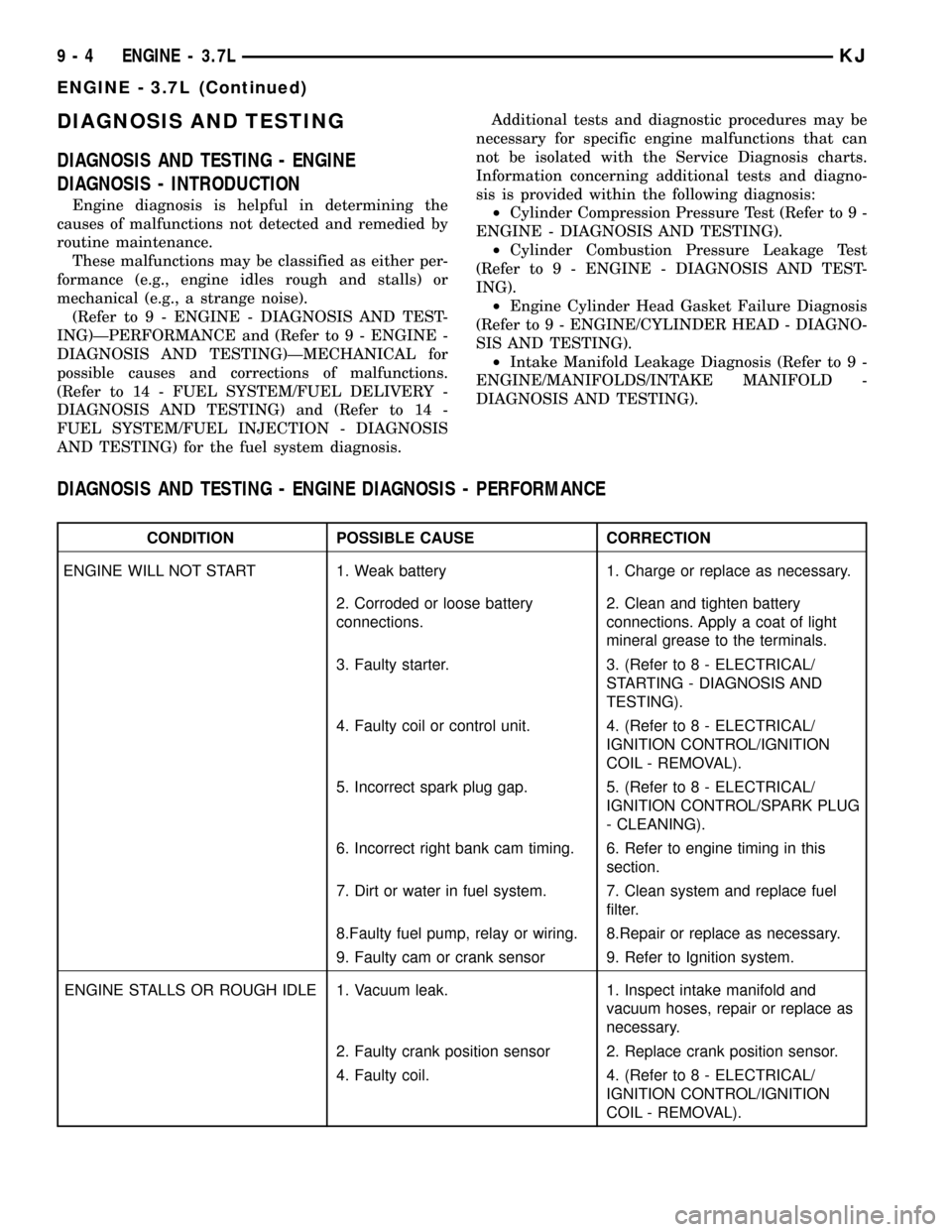
DIAGNOSIS AND TESTING - ENGINE DIAGNOSIS - PERFORMANCE
CONDITION POSSIBLE CAUSE CORRECTION
ENGINE WILL NOT START 1. Weak battery 1. Charge or replace as necessary.
2. Corroded or loose battery
connections.2. Clean and tighten battery
connections. Apply a coat of light
mineral grease to the terminals.
3. Faulty starter. 3. (Refer to 8 - ELECTRICAL/
STARTING - DIAGNOSIS AND
TESTING).
4. Faulty coil or control unit. 4. (Refer to 8 - ELECTRICAL/
IGNITION CONTROL/IGNITION
COIL - REMOVAL).
5. Incorrect spark plug gap. 5. (Refer to 8 - ELECTRICAL/
IGNITION CONTROL/SPARK PLUG
- CLEANING).
6. Incorrect right bank cam timing. 6. Refer to engine timing in this
section.
7. Dirt or water in fuel system. 7. Clean system and replace fuel
filter.
8.Faulty fuel pump, relay or wiring. 8.Repair or replace as necessary.
9. Faulty cam or crank sensor 9. Refer to Ignition system.
ENGINE STALLS OR ROUGH IDLE 1. Vacuum leak. 1. Inspect intake manifold and
vacuum hoses, repair or replace as
necessary.
2. Faulty crank position sensor 2. Replace crank position sensor.
4. Faulty coil. 4. (Refer to 8 - ELECTRICAL/
IGNITION CONTROL/IGNITION
COIL - REMOVAL).
9 - 4 ENGINE - 3.7LKJ
ENGINE - 3.7L (Continued)
Page 1223 of 1803
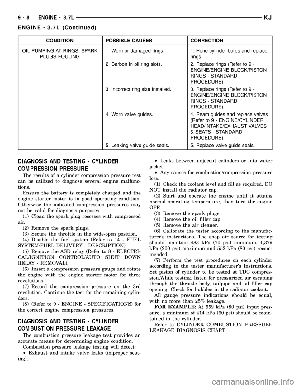
CONDITION POSSIBLE CAUSES CORRECTION
OIL PUMPING AT RINGS; SPARK
PLUGS FOULING1. Worn or damaged rings. 1. Hone cylinder bores and replace
rings.
2. Carbon in oil ring slots. 2. Replace rings (Refer to 9 -
ENGINE/ENGINE BLOCK/PISTON
RINGS - STANDARD
PROCEDURE).
3. Incorrect ring size installed. 3. Replace rings (Refer to 9 -
ENGINE/ENGINE BLOCK/PISTON
RINGS - STANDARD
PROCEDURE).
4. Worn valve guides. 4. Ream guides and replace valves
(Refer to 9 - ENGINE/CYLINDER
HEAD/INTAKE/EXHAUST VALVES
& SEATS - STANDARD
PROCEDURE).
5. Leaking valve guide seals. 5. Replace valve guide seals.
DIAGNOSIS AND TESTING - CYLINDER
COMPRESSION PRESSURE
The results of a cylinder compression pressure test
can be utilized to diagnose several engine malfunc-
tions.
Ensure the battery is completely charged and the
engine starter motor is in good operating condition.
Otherwise the indicated compression pressures may
not be valid for diagnosis purposes.
(1) Clean the spark plug recesses with compressed
air.
(2) Remove the spark plugs.
(3) Secure the throttle in the wide-open position.
(4) Disable the fuel system (Refer to 14 - FUEL
SYSTEM/FUEL DELIVERY - DESCRIPTION).
(5) Remove the ASD relay (Refer to 8 - ELECTRI-
CAL/IGNITION CONTROL/AUTO SHUT DOWN
RELAY - REMOVAL).
(6) Insert a compression pressure gauge and rotate
the engine with the engine starter motor for three
revolutions.
(7) Record the compression pressure on the 3rd
revolution. Continue the test for the remaining cylin-
ders.
(8) (Refer to 9 - ENGINE - SPECIFICATIONS) for
the correct engine compression pressures.
DIAGNOSIS AND TESTING - CYLINDER
COMBUSTION PRESSURE LEAKAGE
The combustion pressure leakage test provides an
accurate means for determining engine condition.
Combustion pressure leakage testing will detect:
²Exhaust and intake valve leaks (improper seat-
ing).²Leaks between adjacent cylinders or into water
jacket.
²Any causes for combustion/compression pressure
loss.
(1) Check the coolant level and fill as required. DO
NOT install the radiator cap.
(2) Start and operate the engine until it attains
normal operating temperature, then turn the engine
OFF.
(3) Remove the spark plugs.
(4) Remove the oil filler cap.
(5) Remove the air cleaner.
(6) Calibrate the tester according to the manufac-
turer's instructions. The shop air source for testing
should maintain 483 kPa (70 psi) minimum, 1,379
kPa (200 psi) maximum and 552 kPa (80 psi) recom-
mended.
(7) Perform the test procedures on each cylinder
according to the tester manufacturer's instructions.
Set piston of cylinder to be tested at TDC compres-
sion,While testing, listen for pressurized air escaping
through the throttle body, tailpipe and oil filler cap
opening. Check for bubbles in the radiator coolant.
All gauge pressure indications should be equal,
with no more than 25% leakage.
FOR EXAMPLE:At 552 kPa (80 psi) input pres-
sure, a minimum of 414 kPa (60 psi) should be main-
tained in the cylinder.
Refer to CYLINDER COMBUSTION PRESSURE
LEAKAGE DIAGNOSIS CHART .
9 - 8 ENGINE - 3.7LKJ
ENGINE - 3.7L (Continued)
Page 1300 of 1803
ENGINE - 2.4L
DESCRIPTION
The 2.4 Liter (148 cu. in.) in-line four cylinder
engine is a double over head camshaft with hydraulic
lifters and four valve per cylinder design. The engine
is free-wheeling; meaning it has provisions for piston-
to-valve clearance. However valve-to-valve interference
can occur, if camshafts are rotated independently.
The cylinders are numbered from front of the
engine to the rear. The firing order is 1±3±4±2.
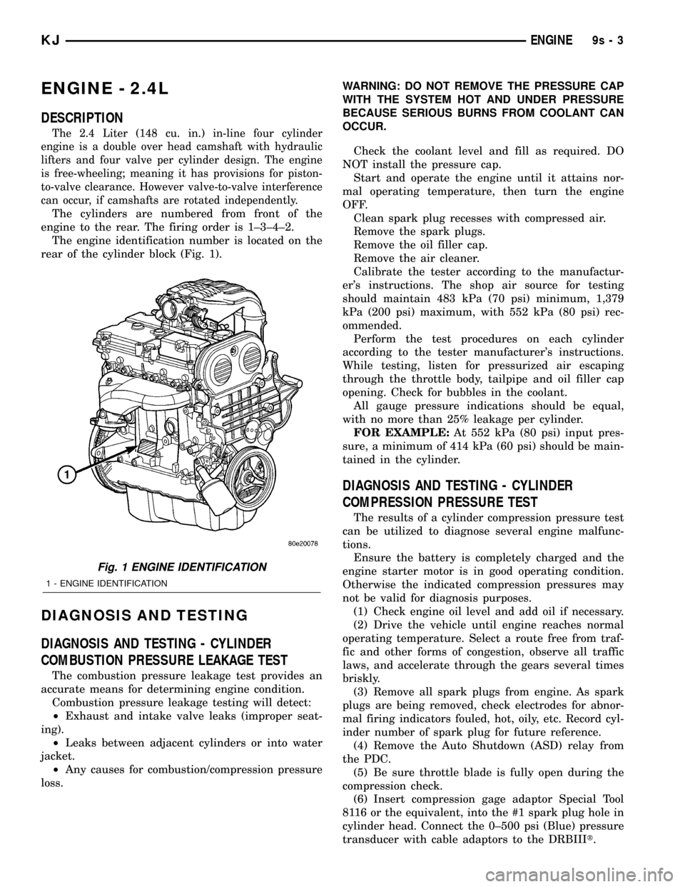
The engine identification number is located on the
rear of the cylinder block (Fig. 1).
DIAGNOSIS AND TESTING
DIAGNOSIS AND TESTING - CYLINDER
COMBUSTION PRESSURE LEAKAGE TEST
The combustion pressure leakage test provides an
accurate means for determining engine condition.
Combustion pressure leakage testing will detect:
²Exhaust and intake valve leaks (improper seat-
ing).
²Leaks between adjacent cylinders or into water
jacket.
²Any causes for combustion/compression pressure
loss.WARNING: DO NOT REMOVE THE PRESSURE CAP
WITH THE SYSTEM HOT AND UNDER PRESSURE
BECAUSE SERIOUS BURNS FROM COOLANT CAN
OCCUR.
Check the coolant level and fill as required. DO
NOT install the pressure cap.
Start and operate the engine until it attains nor-
mal operating temperature, then turn the engine
OFF.
Clean spark plug recesses with compressed air.
Remove the spark plugs.
Remove the oil filler cap.
Remove the air cleaner.
Calibrate the tester according to the manufactur-
er's instructions. The shop air source for testing
should maintain 483 kPa (70 psi) minimum, 1,379
kPa (200 psi) maximum, with 552 kPa (80 psi) rec-
ommended.
Perform the test procedures on each cylinder
according to the tester manufacturer's instructions.
While testing, listen for pressurized air escaping
through the throttle body, tailpipe and oil filler cap
opening. Check for bubbles in the coolant.
All gauge pressure indications should be equal,
with no more than 25% leakage per cylinder.
FOR EXAMPLE:At 552 kPa (80 psi) input pres-
sure, a minimum of 414 kPa (60 psi) should be main-
tained in the cylinder.
DIAGNOSIS AND TESTING - CYLINDER
COMPRESSION PRESSURE TEST
The results of a cylinder compression pressure test
can be utilized to diagnose several engine malfunc-
tions.
Ensure the battery is completely charged and the
engine starter motor is in good operating condition.
Otherwise the indicated compression pressures may
not be valid for diagnosis purposes.
(1) Check engine oil level and add oil if necessary.
(2) Drive the vehicle until engine reaches normal
operating temperature. Select a route free from traf-
fic and other forms of congestion, observe all traffic
laws, and accelerate through the gears several times
briskly.
(3) Remove all spark plugs from engine. As spark
plugs are being removed, check electrodes for abnor-
mal firing indicators fouled, hot, oily, etc. Record cyl-
inder number of spark plug for future reference.
(4) Remove the Auto Shutdown (ASD) relay from
the PDC.
(5) Be sure throttle blade is fully open during the
compression check.
(6) Insert compression gage adaptor Special Tool
8116 or the equivalent, into the #1 spark plug hole in
cylinder head. Connect the 0±500 psi (Blue) pressure
transducer with cable adaptors to the DRBIIIt.
Fig. 1 ENGINE IDENTIFICATION
1 - ENGINE IDENTIFICATION
KJENGINE9s-3