2002 JEEP LIBERTY Low power
[x] Cancel search: Low powerPage 1317 of 1803
Possible indications of the cylinder head gasket
leaking between a cylinder and an adjacent water
jacket are:
²Engine overheating
²Loss of coolant
²Excessive steam (white smoke) emitting from
exhaust
²Coolant foaming
CYLINDER-TO-CYLINDER LEAKAGE TEST
To determine if an engine cylinder head gasket is
leaking between adjacent cylinders, follow the proce-
dures in Cylinder Compression Pressure Test (Refer
to 9 - ENGINE - DIAGNOSIS AND TESTING). An
engine cylinder head gasket leaking between adja-
cent cylinders will result in approximately a 50±70%
reduction in compression pressure.
CYLINDER-TO-WATER JACKET LEAKAGE TEST
WARNING: USE EXTREME CAUTION WHEN THE
ENGINE IS OPERATING WITH COOLANT PRES-
SURE CAP REMOVED.
VISUAL TEST METHOD
With the engine cool, remove the coolant pressure
cap. Start the engine and allow it to warm up until
thermostat opens.
If a large combustion/compression pressure leak
exists, bubbles will be visible in the coolant.
COOLING SYSTEM TESTER METHOD
WARNING: WITH COOLING SYSTEM TESTER IN
PLACE, PRESSURE WILL BUILD UP FAST. EXCES-
SIVE PRESSURE BUILT UP, BY CONTINUOUS
ENGINE OPERATION, MUST BE RELEASED TO A
SAFE PRESSURE POINT. NEVER PERMIT PRES-
SURE TO EXCEED 138 kPa (20 psi).
Install Cooling System Tester 7700 or equivalent to
pressure cap neck. Start the engine and observe the
tester's pressure gauge. If gauge pulsates with every
power stroke of a cylinder a combustion pressure
leak is evident.
CHEMICAL TEST METHOD
Combustion leaks into the cooling system can also
be checked by using Bloc-Chek Kit C-3685-A or
equivalent. Perform test following the procedures
supplied with the tool kit.
REMOVAL - CYLINDER HEAD
(1) Perform fuel system pressure release procedure
before attempting any repairs.(Refer to 14 -FUEL SYSTEM/FUEL DELIVERY - SPECIFICA-
TIONS)
(2) Disconnect battery negative cable.
(3) Drain cooling system. (Refer to 7 - COOLING -
STANDARD PROCEDURE)
(4) Remove air filter housing and inlet tube.
(5) Remove intake manifold.
(6) Remove heater tube support bracket from cyl-
inder head.
(7) Disconnect radiator upper and heater supply
hoses from water outlet connections.
(8) Remove accessory drive belts. (Refer to 7 -
COOLING/ACCESSORY DRIVE/DRIVE BELTS -
REMOVAL)
(9) Raise vehicle and remove exhaust pipe from
manifold.
(10) Remove power steering pump and set aside.
Do not disconnect lines.
(11) Remove accessory drive bracket
(12) Remove ignition coil and wires from engine.
(13) Disconnect cam sensor and fuel injector wir-
ing connectors.
(14) Remove timing belt and camshaft sprockets.
(Refer to 9 - ENGINE/VALVE TIMING/TIMING
BELT/CHAIN AND SPROCKETS - REMOVAL)
(15) Remove timing belt idler pulley and rear tim-
ing belt cover. (Refer to 9 - ENGINE/VALVE TIM-
ING/TIMING BELT / CHAIN COVER(S) -
REMOVAL)
(16) Remove cylinder head cover. (Refer to 9 -
ENGINE/CYLINDER HEAD/CYLINDER HEAD
COVER(S) - REMOVAL)
(17) Remove camshafts (Refer to 9 - ENGINE/
CYLINDER HEAD/CAMSHAFT(S) - REMOVAL).
NOTE: Identify rocker arm position to ensure cor-
rect re-installation in original position, if reused.
(18) Remove rocker arms. (Refer to 9 - ENGINE/
CYLINDER HEAD/ROCKER ARMS - REMOVAL).
(19) Remove cylinder head bolts in REVERSE
sequence of tightening.
(20) Remove cylinder head from engine block.
(21) Inspect and clean cylinder head. (Refer to 9 -
ENGINE/CYLINDER HEAD - INSPECTION) (Refer
to 9 - ENGINE/CYLINDER HEAD - CLEANING)
CLEANING
To ensure engine gasket sealing, proper surface
preparation must be performed, especially with the
use of aluminum engine components and multi-layer
steel cylinder head gaskets.
NOTE: Multi-Layer Steel (MLS) head gaskets require
a scratch free sealing surface.
9s - 20 ENGINEKJ
CYLINDER HEAD (Continued)
Page 1319 of 1803
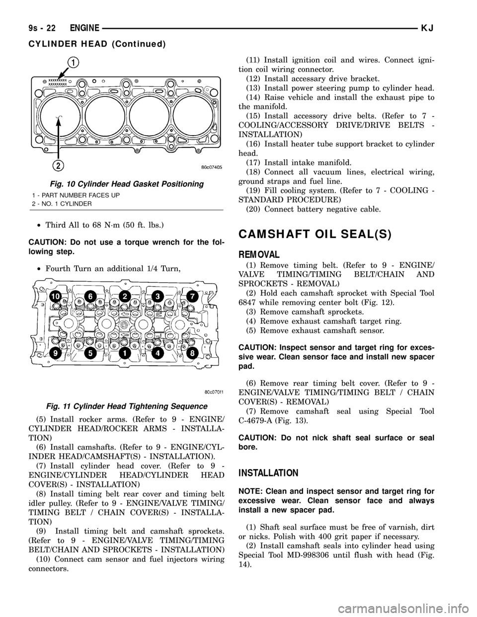
²Third All to 68 N´m (50 ft. lbs.)
CAUTION: Do not use a torque wrench for the fol-
lowing step.
²Fourth Turn an additional 1/4 Turn,
(5) Install rocker arms. (Refer to 9 - ENGINE/
CYLINDER HEAD/ROCKER ARMS - INSTALLA-
TION)
(6) Install camshafts. (Refer to 9 - ENGINE/CYL-
INDER HEAD/CAMSHAFT(S) - INSTALLATION).
(7) Install cylinder head cover. (Refer to 9 -
ENGINE/CYLINDER HEAD/CYLINDER HEAD
COVER(S) - INSTALLATION)
(8) Install timing belt rear cover and timing belt
idler pulley. (Refer to 9 - ENGINE/VALVE TIMING/
TIMING BELT / CHAIN COVER(S) - INSTALLA-
TION)
(9) Install timing belt and camshaft sprockets.
(Refer to 9 - ENGINE/VALVE TIMING/TIMING
BELT/CHAIN AND SPROCKETS - INSTALLATION)
(10) Connect cam sensor and fuel injectors wiring
connectors.(11) Install ignition coil and wires. Connect igni-
tion coil wiring connector.
(12) Install accessary drive bracket.
(13) Install power steering pump to cylinder head.
(14) Raise vehicle and install the exhaust pipe to
the manifold.
(15) Install accessory drive belts. (Refer to 7 -
COOLING/ACCESSORY DRIVE/DRIVE BELTS -
INSTALLATION)
(16) Install heater tube support bracket to cylinder
head.
(17) Install intake manifold.
(18) Connect all vacuum lines, electrical wiring,
ground straps and fuel line.
(19) Fill cooling system. (Refer to 7 - COOLING -
STANDARD PROCEDURE)
(20) Connect battery negative cable.
CAMSHAFT OIL SEAL(S)
REMOVAL
(1) Remove timing belt. (Refer to 9 - ENGINE/
VALVE TIMING/TIMING BELT/CHAIN AND
SPROCKETS - REMOVAL)
(2) Hold each camshaft sprocket with Special Tool
6847 while removing center bolt (Fig. 12).
(3) Remove camshaft sprockets.
(4) Remove exhaust camshaft target ring.
(5) Remove exhaust camshaft sensor.
CAUTION: Inspect sensor and target ring for exces-
sive wear. Clean sensor face and install new spacer
pad.
(6) Remove rear timing belt cover. (Refer to 9 -
ENGINE/VALVE TIMING/TIMING BELT / CHAIN
COVER(S) - REMOVAL)
(7) Remove camshaft seal using Special Tool
C-4679-A (Fig. 13).
CAUTION: Do not nick shaft seal surface or seal
bore.
INSTALLATION
NOTE: Clean and inspect sensor and target ring for
excessive wear. Clean sensor face and always
install a new spacer pad.
(1) Shaft seal surface must be free of varnish, dirt
or nicks. Polish with 400 grit paper if necessary.
(2) Install camshaft seals into cylinder head using
Special Tool MD-998306 until flush with head (Fig.
14).
Fig. 10 Cylinder Head Gasket Positioning
1 - PART NUMBER FACES UP
2 - NO. 1 CYLINDER
Fig. 11 Cylinder Head Tightening Sequence
9s - 22 ENGINEKJ
CYLINDER HEAD (Continued)
Page 1341 of 1803
STRUCTURAL COLLAR
REMOVAL
(1) Raise vehicle on hoist.
(2) Remove structural collar attaching bolts.
(3) Remove collar.
INSTALLATION
CAUTION: Torque procedure for the structural collar
must be followed or damage could occur to oil pan
and collar.
(1) Perform the following steps for installing struc-
tural collar.
²Step 1: Position collar between transmission and
oil pan. Install collar to transmission bolts,hand
start only.
²Step 2: Install collar to oil pan bolts,hand snug
only.
²Step 3: Tighten collar to transmission bolts.
²Step 4: Tighten collar to oil pan bolts.
(2) Lower vehicle.
ENGINE MOUNTING
DESCRIPTION
The engine mounting system consist of three
mounts; right and a left side support the powertrain,
and rear mount to control powertrain torque. The
mounts are of molded rubber material.
FRONT MOUNT
REMOVAL
(1) Raise vehicle on hoist.
(2) Remove the front engine mount through bolt
from the insulator.
(3) Remove the engine front mount bolts and
remove the insulator assembly.
(4) Remove the front mounting bracket from
engine, if necessary.
INSTALLATION
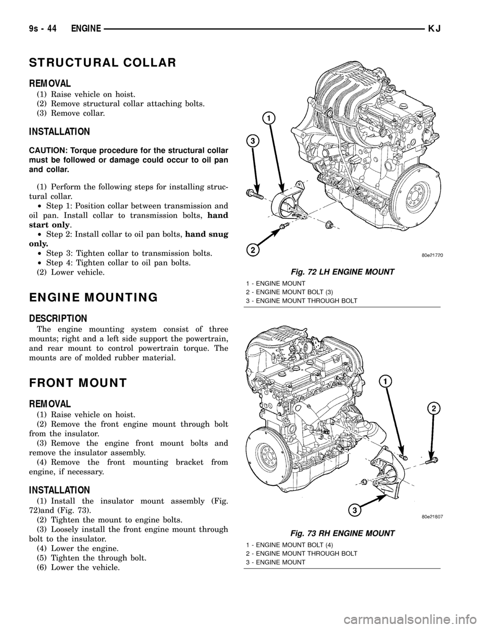
(1) Install the insulator mount assembly (Fig.
72)and (Fig. 73).
(2) Tighten the mount to engine bolts.
(3) Loosely install the front engine mount through
bolt to the insulator.
(4) Lower the engine.
(5) Tighten the through bolt.
(6) Lower the vehicle.
Fig. 72 LH ENGINE MOUNT
1 - ENGINE MOUNT
2 - ENGINE MOUNT BOLT (3)
3 - ENGINE MOUNT THROUGH BOLT
Fig. 73 RH ENGINE MOUNT
1 - ENGINE MOUNT BOLT (4)
2 - ENGINE MOUNT THROUGH BOLT
3 - ENGINE MOUNT
9s - 44 ENGINEKJ
Page 1345 of 1803
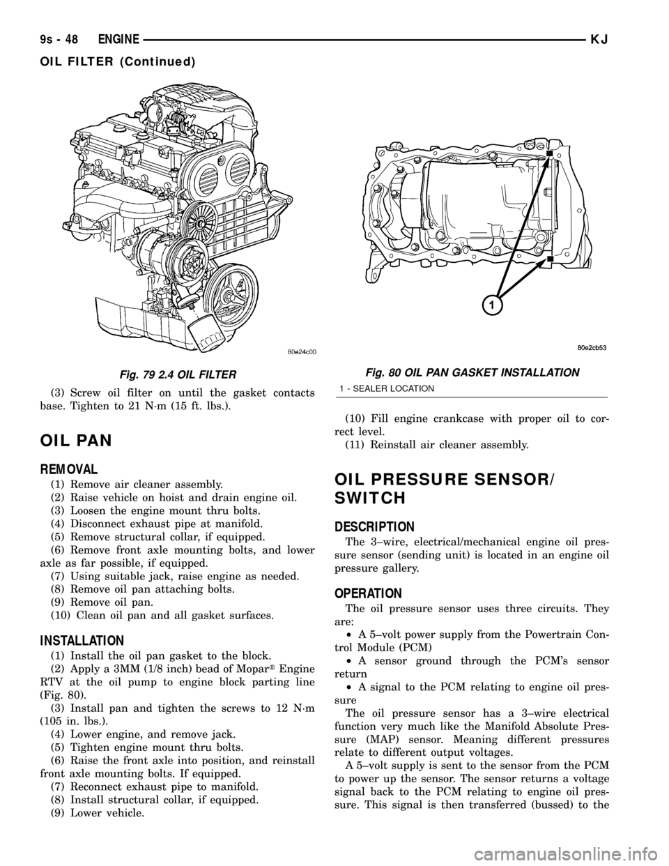
(3) Screw oil filter on until the gasket contacts
base. Tighten to 21 N´m (15 ft. lbs.).
OIL PAN
REMOVAL
(1) Remove air cleaner assembly.
(2) Raise vehicle on hoist and drain engine oil.
(3) Loosen the engine mount thru bolts.
(4) Disconnect exhaust pipe at manifold.
(5) Remove structural collar, if equipped.
(6) Remove front axle mounting bolts, and lower
axle as far possible, if equipped.
(7) Using suitable jack, raise engine as needed.
(8) Remove oil pan attaching bolts.
(9) Remove oil pan.
(10) Clean oil pan and all gasket surfaces.
INSTALLATION
(1) Install the oil pan gasket to the block.
(2) Apply a 3MM (1/8 inch) bead of MopartEngine
RTV at the oil pump to engine block parting line
(Fig. 80).
(3) Install pan and tighten the screws to 12 N´m
(105 in. lbs.).
(4) Lower engine, and remove jack.
(5) Tighten engine mount thru bolts.
(6) Raise the front axle into position, and reinstall
front axle mounting bolts. If equipped.
(7) Reconnect exhaust pipe to manifold.
(8) Install structural collar, if equipped.
(9) Lower vehicle.(10) Fill engine crankcase with proper oil to cor-
rect level.
(11) Reinstall air cleaner assembly.
OIL PRESSURE SENSOR/
SWITCH
DESCRIPTION
The 3±wire, electrical/mechanical engine oil pres-
sure sensor (sending unit) is located in an engine oil
pressure gallery.
OPERATION
The oil pressure sensor uses three circuits. They
are:
²A 5±volt power supply from the Powertrain Con-
trol Module (PCM)
²A sensor ground through the PCM's sensor
return
²A signal to the PCM relating to engine oil pres-
sure
The oil pressure sensor has a 3±wire electrical
function very much like the Manifold Absolute Pres-
sure (MAP) sensor. Meaning different pressures
relate to different output voltages.
A 5±volt supply is sent to the sensor from the PCM
to power up the sensor. The sensor returns a voltage
signal back to the PCM relating to engine oil pres-
sure. This signal is then transferred (bussed) to the
Fig. 79 2.4 OIL FILTERFig. 80 OIL PAN GASKET INSTALLATION
1 - SEALER LOCATION
9s - 48 ENGINEKJ
OIL FILTER (Continued)
Page 1349 of 1803
(2) Spray a small stream of water (Spray Bottle) at
the suspected leak area.
(3) If engine RPM'S change, the area of the sus-
pected leak has been found.
(4) Repair as required.
REMOVAL
(1) Disconnect negative cable from battery.
(2) Disconnect connector from inlet air tempera-
ture sensor.
(3) Disconnect air intake tube at throttle body and
remove upper air cleaner housing.
(4) Disconnect connector from throttle position
sensor (TPS).
(5) Disconnect connector from idle air control (IAC)
motor.
(6) Disconnect connector from MAP sensor.
(7) Remove vacuum lines for purge solenoid and
PCV valve at intake manifold.
(8) Remove vacuum lines for power brake booster,
LDP, EGR transducer, and speed control vacuum res-
ervoir (if equipped) at intake manifold fittings.
(9) Disconnect throttle, speed control (if equipped),
and transaxle control (if equipped) and cables from
throttle lever and bracket. (Refer to 14 - FUEL SYS-
TEM/FUEL INJECTION/THROTTLE CONTROL
CABLE - REMOVAL)
(10) Perform fuel system pressure release proce-
durebefore attempting any repairs.(Refer to 14 -
FUEL SYSTEM/FUEL DELIVERY - STANDARD
PROCEDURE)
(11) Disconnect fuel line. (Refer to 14 - FUEL SYS-
TEM/FUEL DELIVERY/QUICK CONNECT FIT-
TING - STANDARD PROCEDURE)
(12) Disconnect coolant temperature sensor/fuel
injector wire harness connector.
(13) Disconnect fuel injector harness.
(14) Remove intake manifold to cylinder head fas-
teners.
(15) Remove the manifold from engine.
CAUTION: Cover intake manifold openings to pre-
vent foreign material from entering engine.
(16) Inspect the manifold. (Refer to 9 - ENGINE/
MANIFOLDS/INTAKE MANIFOLD - INSPECTION)
INSPECTION
(1) Check manifold surfaces for flatness with
straight edge. Surface must be flat within 0.15 mm
per 300 mm (0.006 in. per foot) of manifold length.
(2) Inspect manifold for cracks or distortion.
Replace manifold if necessary.
INSTALLATION
(1) Clean manifold sealing surfaces.
(2) Install new manifold to cylinder head seals.
(3) Install manifold to head.
(4) Install and tighten intake manifold fasteners to
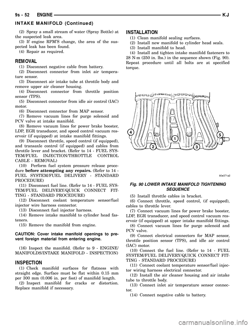
28 N´m (250 in. lbs.) in the sequence shown (Fig. 90).
Repeat procedure until all bolts are at specified
torque.
(5) Install throttle cables in bracket.
(6) Connect throttle, speed control, (if equipped),
cables to throttle lever.
(7) Connect vacuum lines for power brake booster,
LDP, EGR transducer, and speed control vacuum res-
ervoir (if equipped) at upper intake manifold fittings.
(8) Connect vacuum lines for purge solenoid and
PCV valve.
(9) Connect electrical connectors for MAP sensor,
throttle position sensor (TPS), and idle air control
(IAC) motor.
(10) Connect the fuel line. (Refer to 14 - FUEL
SYSTEM/FUEL DELIVERY/QUICK CONNECT FIT-
TING - STANDARD PROCEDURE)
(11) Connect coolant temperature sensor/fuel injec-
tor wiring harness electrical connector.
(12) Install the air cleaner housing and air intake
tube to throttle body.
(13) Connect inlet air temperature sensor connec-
tor.
(14) Connect negative cable to battery.
Fig. 90 LOWER INTAKE MANIFOLD TIGHTENING
SEQUENCE
9s - 52 ENGINEKJ
INTAKE MANIFOLD (Continued)
Page 1379 of 1803
SPECIFICATIONS - TORQUE
DESCRIPTION N´m Ft. Lbs. In. Lbs.
ENGINE CRADLE CROSSMEMBER INNER RAIL BOLTS 47 35 Ð
ENGINE CRADLE CROSSMEMBER MOUNTING BOLTS 122 90 Ð
ENGINE MOUNT THROUGH BOLTS/NUTS 88 65 Ð
FRONT SKID PLATE BOLTS 61 45 Ð
FRONT TOW HOOK NUTS/BOLT 61 45 Ð
FUEL TANK SKID PLATE 88 65 Ð
REAR CROSSMEMBER BOLTS 47 35 Ð
REAR TOW HOOK BOLTS 88 65 Ð
TRAILER HITCH BOLTS 88 65 Ð
TRANSFER CASE SKID PLATE BOLTS 34 25 Ð
TRANSMISSION MOUNT THROUGH BOLT/NUT 88 65 Ð
FRONT SKID PLATE
REMOVAL
(1) Raise and support the vehicle.
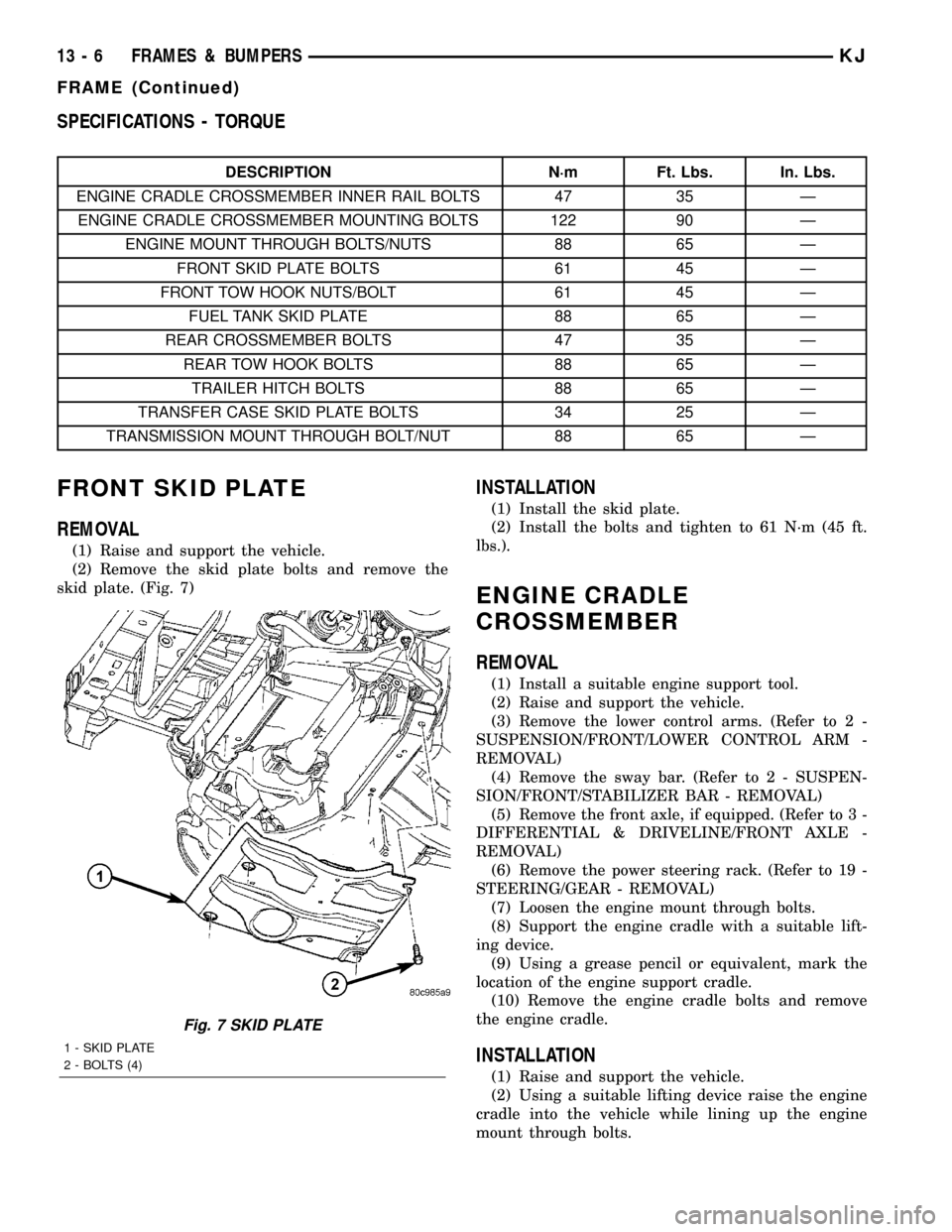
(2) Remove the skid plate bolts and remove the
skid plate. (Fig. 7)
INSTALLATION
(1) Install the skid plate.
(2) Install the bolts and tighten to 61 N´m (45 ft.
lbs.).
ENGINE CRADLE
CROSSMEMBER
REMOVAL
(1) Install a suitable engine support tool.
(2) Raise and support the vehicle.
(3) Remove the lower control arms. (Refer to 2 -
SUSPENSION/FRONT/LOWER CONTROL ARM -
REMOVAL)
(4) Remove the sway bar. (Refer to 2 - SUSPEN-
SION/FRONT/STABILIZER BAR - REMOVAL)
(5) Remove the front axle, if equipped. (Refer to 3 -
DIFFERENTIAL & DRIVELINE/FRONT AXLE -
REMOVAL)
(6) Remove the power steering rack. (Refer to 19 -
STEERING/GEAR - REMOVAL)
(7) Loosen the engine mount through bolts.
(8) Support the engine cradle with a suitable lift-
ing device.
(9) Using a grease pencil or equivalent, mark the
location of the engine support cradle.
(10) Remove the engine cradle bolts and remove
the engine cradle.
INSTALLATION
(1) Raise and support the vehicle.
(2) Using a suitable lifting device raise the engine
cradle into the vehicle while lining up the engine
mount through bolts.
Fig. 7 SKID PLATE
1 - SKID PLATE
2 - BOLTS (4)
13 - 6 FRAMES & BUMPERSKJ
FRAME (Continued)
Page 1380 of 1803
(3) Align the engine cradle to the marks made dur-
ing removal and install the mounting and inner rail
bolts.
(4) Tighten the mounting bolts to 122 N´m (90 ft.
lbs.).
(5) Tighten the inner rail bolts to 47 N´m (35 ft.
lbs.).
(6) Tighten the engine mount through bolts to 88
N´m (65 ft. lbs.).
(7) Install the power steering rack. (Refer to 19 -
STEERING/GEAR - INSTALLATION)
(8) Install the front axle, if equipped. (Refer to 3 -
DIFFERENTIAL & DRIVELINE/FRONT AXLE -
INSTALLATION)
(9) Install the stabilizer bar. (Refer to 2 - SUS-
PENSION/FRONT/STABILIZER BAR - INSTALLA-
TION)
(10) Install the lower control arms. (Refer to 2 -
SUSPENSION/FRONT/LOWER CONTROL ARM -
INSTALLATION)
(11) Lower the vehicle and remove the engine sup-
port tool.
TRANSFER CASE SKID PLATE
REMOVAL
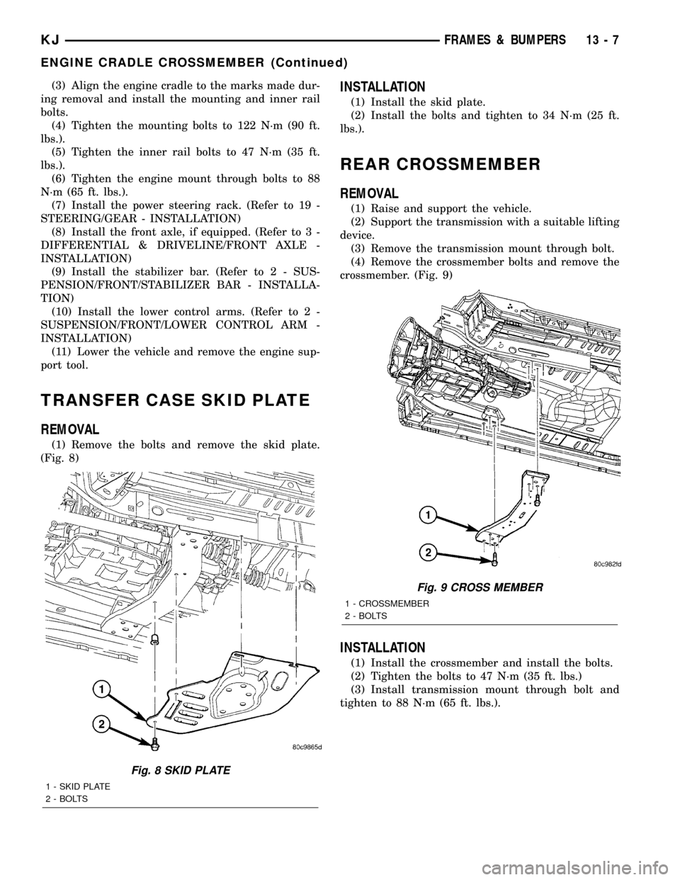
(1) Remove the bolts and remove the skid plate.
(Fig. 8)
INSTALLATION
(1) Install the skid plate.
(2) Install the bolts and tighten to 34 N´m (25 ft.
lbs.).
REAR CROSSMEMBER
REMOVAL
(1) Raise and support the vehicle.
(2) Support the transmission with a suitable lifting
device.
(3) Remove the transmission mount through bolt.
(4) Remove the crossmember bolts and remove the
crossmember. (Fig. 9)
INSTALLATION
(1) Install the crossmember and install the bolts.
(2) Tighten the bolts to 47 N´m (35 ft. lbs.)
(3) Install transmission mount through bolt and
tighten to 88 N´m (65 ft. lbs.).
Fig. 8 SKID PLATE
1 - SKID PLATE
2 - BOLTS
Fig. 9 CROSS MEMBER
1 - CROSSMEMBER
2 - BOLTS
KJFRAMES & BUMPERS 13 - 7
ENGINE CRADLE CROSSMEMBER (Continued)
Page 1386 of 1803
(8) Pressure should not fall below30 psi for five
minutes.
(9) If pressure falls below 30 psi, it must be deter-
mined if a fuel injector, the check valve within the
fuel pump module, or a fuel tube/line is leaking.
(10) Again, start engine and bring to normal oper-
ating temperature.
(11) Shut engine off.
(12)Testing for fuel injector or fuel rail leak-
age:Clamp off the rubber hose portion of Adaptor
Tool between the fuel rail and the test port ªTº on
Adapter Tool. If pressure now holds at or above 30
psi, a fuel injector or the fuel rail is leaking.
(13)Testing for fuel pump check valve, filter,
regulator check valve or fuel tube/line leakage:
Clamp off the rubber hose portion of Adaptor Tool
between the vehicle fuel line and test port ªTº on
Adapter Tool. If pressure now holds at or above 30
psi, a leak may be found at a fuel tube/line. If no
leaks are found at fuel tubes or lines, one of the
check valves in either the electric fuel pump, fuel fil-
ter or fuel pressure regulator may be leaking.
Note: A quick loss of pressure usually indicates a
defective check valve in the pressure regulator. A
slow loss of pressure usually indicates a defective
check valve in the bottom of the fuel pump module.
The check valves are not serviced separately. Also,
the electric fuel pump is not serviced separately.
STANDARD PROCEDURE - FUEL SYSTEM
PRESSURE RELEASE
Use following procedure if the fuel injector
rail is, or is not equipped with a fuel pressure
test port.
(1) Remove fuel fill cap.
(2) Remove fuel pump relay from Power Distribu-
tion Center (PDC). For location of relay, refer to label
on underside of PDC cover.(3) Start and run engine until it stalls.
(4) Attempt restarting engine until it will no
longer run.
(5) Turn ignition key to OFF position.
CAUTION: Steps 1, 2, 3 and 4 must be performed to
relieve high pressure fuel from within fuel rail. Do
not attempt to use following steps to relieve this
pressure as excessive fuel will be forced into a cyl-
inder chamber.
(6) Unplug connector from any fuel injector.
(7) Attach one end of a jumper wire with alligator
clips (18 gauge or smaller) to either injector terminal.
(8) Connect other end of jumper wire to positive
side of battery.
(9) Connect one end of a second jumper wire to
remaining injector terminal.
CAUTION: Powering an injector for more than a few
seconds will permanently damage the injector.
(10) Momentarily touch other end of jumper wire
to negative terminal of battery for no more than a
few seconds.
(11) Place a rag or towel below fuel line quick-con-
nect fitting at fuel rail.
(12) Disconnect quick-connect fitting at fuel rail.
Refer to Quick-Connect Fittings.
(13) Return fuel pump relay to PDC.
(14) One or more Diagnostic Trouble Codes (DTC's)
may have been stored in PCM memory due to fuel
pump relay removal. The DRBtscan tool must be
used to erase a DTC.
14 - 4 FUEL DELIVERYKJ
FUEL DELIVERY (Continued)