2002 JEEP LIBERTY Low power
[x] Cancel search: Low powerPage 1448 of 1803

NOTE: Power steering pumps have different pres-
sure rates and are not interchangeable with other
pumps.
STANDARD PROCEDURE - POWER STEERING
PUMP - INITIAL OPERATION
WARNING: THE FLUID LEVEL SHOULD BE
CHECKED WITH ENGINE OFF TO PREVENT INJURY
FROM MOVING COMPONENTS.
CAUTION: Use MOPAR Power Steering Fluid or
equivalent. Do not use automatic transmission fluid
and do not overfill.
Wipe filler cap clean, then check the fluid level.
The dipstick should indicateCOLDwhen the fluid is
at normal ambient temperature.
(1) Fill the pump fluid reservoir to the proper level
and let the fluid settle for at least two minutes.
(2) Raise the front wheels off the ground.
(3) Slowly turn the steering wheel right and left,
lightly contacting the wheel stops at least 20 times.
(4) Check the fluid level add if necessary.
(5) Lower the vehicle, start the engine and turn
the steering wheel slowly from lock to lock.
(6) Stop the engine and check the fluid level and
refill as required.
CAUTION: Do not run a vehicle with foamy fluid for
an extended period. This may cause pump damage.
(7) If the fluid is extremely foamy or milky look-
ing, allow the vehicle to stand a few minutes and
repeat the procedure.
(8) Add fluid if necessary. Repeat the above proce-
dure until the fluid level remains constant after run-
ning the engine.
REMOVAL
REMOVAL - 3.7L
(1) Siphon out as much power steering fluid as
possible.
(2) Remove the radiator cross member (Refer to 23
- BODY/EXTERIOR/RADIATOR CROSSMEMBER -
REMOVAL).
(3) Remove the engine cooling fan (Refer to 7 -
COOLING/ENGINE/RADIATOR FAN - REMOVAL).
(4) Remove the fan shroud
(5) Remove the serpentine drive belt (Refer to 7 -
COOLING/ACCESSORY DRIVE/DRIVE BELTS -
REMOVAL).
(6) Remove the power steering high pressure hose
at the pump.
(7) Remove the return hose at the pump.
(8) Remove the three bolts securing the pump to
the bracket thru the holes in the pulley. (Fig. 3)
(9) Remove the pump from the vehicle.
REMOVAL - 2.4L
CAUTION: On vehicles equipped with the 2.4L, Do
not reuse the old power steering pump pulley it is
not intended for reuse. A new pulley must be
installed if removed.
(1) Siphon out as much power steering fluid as
possible.
(2) Remove the serpentine drive belt.
(3) Remove the power steering high pressure hose
at the pump using care not to remove the flow con-
trol valve.
(4) Remove the return hose at the pump.
Fig. 2 FLUID RESERVOIR - 2.4L
Fig. 3 POWER STEERING PUMP - 3.7L
1 - MOUNTING BOLTS
2 - RESERVOIR
3 - STEEL PULLEY
19 - 18 PUMPKJ
PUMP (Continued)
Page 1449 of 1803

(5) Remove the two nuts securing the wire loom
behind the pump bracket.
(6) Remove the three bolts securing the pump to
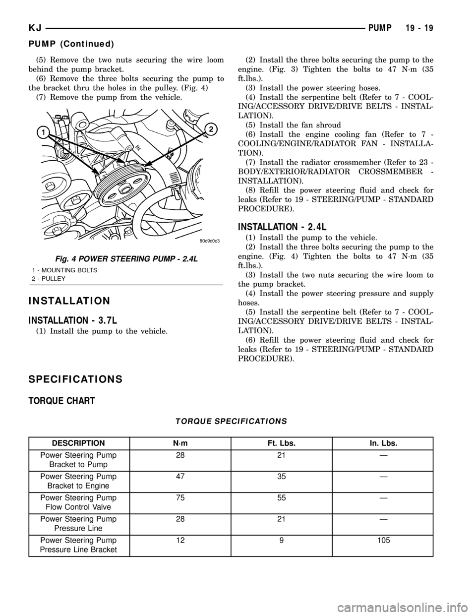
the bracket thru the holes in the pulley. (Fig. 4)
(7) Remove the pump from the vehicle.
INSTALLATION
INSTALLATION - 3.7L
(1) Install the pump to the vehicle.(2) Install the three bolts securing the pump to the
engine. (Fig. 3) Tighten the bolts to 47 N´m (35
ft.lbs.).
(3) Install the power steering hoses.
(4) Install the serpentine belt (Refer to 7 - COOL-
ING/ACCESSORY DRIVE/DRIVE BELTS - INSTAL-
LATION).
(5) Install the fan shroud
(6) Install the engine cooling fan (Refer to 7 -
COOLING/ENGINE/RADIATOR FAN - INSTALLA-
TION).
(7) Install the radiator crossmember (Refer to 23 -
BODY/EXTERIOR/RADIATOR CROSSMEMBER -
INSTALLATION).
(8) Refill the power steering fluid and check for
leaks (Refer to 19 - STEERING/PUMP - STANDARD
PROCEDURE).
INSTALLATION - 2.4L
(1) Install the pump to the vehicle.
(2) Install the three bolts securing the pump to the
engine. (Fig. 4) Tighten the bolts to 47 N´m (35
ft.lbs.).
(3) Install the two nuts securing the wire loom to
the pump bracket.
(4) Install the power steering pressure and supply
hoses.
(5) Install the serpentine belt (Refer to 7 - COOL-
ING/ACCESSORY DRIVE/DRIVE BELTS - INSTAL-
LATION).
(6) Refill the power steering fluid and check for
leaks (Refer to 19 - STEERING/PUMP - STANDARD
PROCEDURE).
SPECIFICATIONS
TORQUE CHART
TORQUE SPECIFICATIONS
DESCRIPTION N´m Ft. Lbs. In. Lbs.
Power Steering Pump
Bracket to Pump28 21 Ð
Power Steering Pump
Bracket to Engine47 35 Ð
Power Steering Pump
Flow Control Valve75 55 Ð
Power Steering Pump
Pressure Line28 21 Ð
Power Steering Pump
Pressure Line Bracket12 9 105
Fig. 4 POWER STEERING PUMP - 2.4L
1 - MOUNTING BOLTS
2 - PULLEY
KJPUMP 19 - 19
PUMP (Continued)
Page 1450 of 1803

SPECIAL TOOLS
POWER STEERING PUMP
FLUID COOLER
DESCRIPTION
The power steering fluid cooler is located at the
front of the vehicle. It is mounted to the radiator
lower support just forward of the air-conditioning
condenser and just rearward of the front fascia. The
cooler is positioned so it is in the air flow through the
front fascia of the vehicle (Fig. 5)
OPERATION
The purpose of the power steering fluid cooler is to
keep the temperature of the power steering system
fluid from rising to a level that would affect the per-
formance of the power steering system.
The cooler used on this vehicle is referred to as a
fluid-to-air type cooler. This means that the air flow
across the fin/tubes of the cooler is used to extract
the heat from the cooler which it has absorbed from
the power steering fluid flowing through it. The
cooler is placed in series with the power steering
fluid return line, between the steering gear and the
power steering fluid reservoir. This lowers the tem-
perature of the power steering fluid prior to it enter-
ing the power steering fluid reservoir where it is
resupplied to the power steering pump.
REMOVAL
(1) Remove the return line at the gear.
(2) Remove the return line at the reservoir.
(3) Remove the grille (Refer to 23 - BODY/EXTE-
RIOR/GRILLE - REMOVAL).
(4) Remove the two cooler mounting bolts. (Fig. 5)
(5) Remove the cooler from the vehicle.
INSTALLATION
(1) Install the cooler to the vehicle.
(2) Install the two cooler mounting bolts. (Fig. 5).
(3) Install the grille (Refer to 23 - BODY/EXTERI-
OR/GRILLE - INSTALLATION).
(4) Install the return line at the reservoir.
(5) Install the return line at the gear.
(6) Refill the power steering fluid and check for
leaks (Refer to 19 - STEERING/PUMP - STANDARD
PROCEDURE).
Analyzer Set, Power Steering Flow/Pressure 6815
Adapters, Power Steering Flow/Pressure Tester
6893
Puller C-4333
Installer, Power Steering Pulley C-4063B
Fig. 5 FLUID COOLER
1 - FLUID COOLER
2 - MOUNTING BOLTS
19 - 20 PUMPKJ
PUMP (Continued)
Page 1452 of 1803

(6) Install the serpentine belt (Refer to 7 - COOL-
ING/ACCESSORY DRIVE/DRIVE BELTS - INSTAL-
LATION).
(7) Install the fan shroud.
(8) Install the fan (Refer to 7 - COOLING/EN-
GINE/RADIATOR FAN - INSTALLATION).
(9) Install the radiator crossmember (Refer to 23 -
BODY/EXTERIOR/RADIATOR CROSSMEMBER -
INSTALLATION).
(10) Refill the power steering fluid (Refer to 19 -
STEERING/PUMP - STANDARD PROCEDURE).
INSTALLATION - RETURN HOSE (GEAR TO THE
COOLER)
(1) Install the return hose to the vehicle. (Fig. 7)
(2) Install the return hose mounting bracket bolts
to the front cradle.
(3) Install the return hose at the cooler.
(4) Install the return hose at the gear 28 N´m (21
ft.lbs.).
(5) Install the serpentine belt (Refer to 7 - COOL-
ING/ACCESSORY DRIVE/DRIVE BELTS - INSTAL-
LATION).
(6) Install the fan shroud.
(7) Install the fan (Refer to 7 - COOLING/EN-
GINE/RADIATOR FAN - INSTALLATION).
(8) Install the radiator crossmember (Refer to 23 -
BODY/EXTERIOR/RADIATOR CROSSMEMBER -
INSTALLATION).
(9) Refill the power steering fluid (Refer to 19 -
STEERING/PUMP - STANDARD PROCEDURE).
INSTALLATION - RETURN HOSE (RESERVOIR
TO THE COOLER)
(1) Install the return hose to the vehicle.
(2) Install the return hose to the pump reservoir.
(3) Install the return hose at the cooler.
(4) Refill the power steering fluid (Refer to 19 -
STEERING/PUMP - STANDARD PROCEDURE).
POWER STEERING PRESSURE
SWITCH
DESCRIPTION
A pressure sensing switch is used in the power
steering system. It is mounted on the high-pressure
steering hose. This switch will be used with both
2.4L and 3.7L engines.
OPERATION
The switch is used on both the 2.4L 4±cylinder and
3.7L V-6 engines.
The power steering pressure switch provides an
input to the Powertrain Control Module (PCM). This
input is provided during periods of high steering
pump load and low engine rpm; such as during park-
ing maneuvers. The PCM increases the idle speed
through the Idle Air Control (IAC) motor. This is
done to prevent the engine from stalling under the
increased load.
When steering pump pressure exceeds 3275 kPa
690 kPa (475 psi 100 psi), the Normally Closed
(NC) switch will open and the PCM will increase the
engine idle speed. This will prevent the engine from
stalling.
When pump pressure drops to approximately 1379
kPa (200 psi), the switch circuit will re-close and
engine idle speed will return to its previous setting.
REMOVAL
The power steering pressure switch is installed in
the power steering high-pressure hose (Fig. 9).
(1) Remove the high pressure power steering
hose(Refer to 19 - STEERING/PUMP/HOSES -
REMOVAL).
(2) Disconnect electrical connector from power
steering pressure switch.
(3) Place a small container or shop towel beneath
switch to collect any excess fluid.
(4) Remove switch. Use back-up wrench on power
steering line to prevent line bending.
INSTALLATION
(1) Install power steering switch into power steer-
ing line. (Fig. 9)
(2) Tighten to 9.6 N´m (85 in. lbs.) torque.
Fig. 8 HIGH PRESSURE HOSE ASSEMBLY
1 - HIGH PRESSURE POWER STEERING HOSE
2 - MOUNTING BRACKET
3 - POWER STEERING PRESURE SWITCH
19 - 22 PUMPKJ
HOSES (Continued)
Page 1585 of 1803

LATCH
REMOVAL
(1) Remove the grill. (Refer to 23 - BODY/EXTERI-
OR/GRILLE - REMOVAL)
(2) Remove the latch support bracket bolts and
position the latch assembly aside. (Fig. 1)
(3) Remove the two latch nuts.
(4) Disconnect the release cable.
INSTALLATION
(1) Connect the release cable and install the latch
onto the support bracket.
(2) Install the two nuts and tighten to 12 N´m (9
ft. lbs.).
(3) Install the support bracket and the bolts.
(4) Tighten the bolts to 12 N´m (9 ft. lbs.).
(5) Install the grill. (Refer to 23 - BODY/EXTERI-
OR/GRILLE - INSTALLATION)
LATCH RELEASE CABLE
REMOVAL
(1) Remove the battery. (Refer to 8 - ELECTRI-
CAL/BATTERY SYSTEM/BATTERY - REMOVAL)
(2) Remove the hood latch. (Refer to 23 - BODY/
HOOD/LATCH - REMOVAL)(3) Remove the powertrain control module. (Refer
to 8 - ELECTRICAL/ELECTRONIC CONTROL
MODULES/POWERTRAIN CONTROL MODULE -
REMOVAL)
(4) Remove the hood release handle. (Refer to 23 -
BODY/HOOD/LATCH RELEASE HANDLE -
REMOVAL)
(5) Disconnect the attaching clips and remove the
cable from the inside.
INSTALLATION
(1) Install the cable from the inside and attach the
retaining clips.
(2) Install the hood latch release handle. (Refer to
23 - BODY/HOOD/LATCH RELEASE HANDLE -
INSTALLATION)
(3) Install the powertrain control module. (Refer to
8 - ELECTRICAL/ELECTRONIC CONTROL MOD-
ULES/POWERTRAIN CONTROL MODULE -
INSTALLATION)
(4) Install the hood latch. (Refer to 23 - BODY/
HOOD/LATCH - INSTALLATION)
(5) Install the battery. (Refer to 8 - ELECTRICAL/
BATTERY SYSTEM/BATTERY - INSTALLATION)
SUPPORT CYLINDER
REMOVAL
(1) Open the hood and support.
(2) Release the upper and lower clips.
(3) Remove the support cylinder.
INSTALLATION
(1) Install the support cylinder over the ball studs
with the thin end down.
(2) Install the retaining clips and remove the sup-
port from the hood.
LATCH RELEASE HANDLE
REMOVAL
(1) Remove the cowl trim panel. (Refer to 23 -
BODY/INTERIOR/COWL TRIM COVER -
REMOVAL)
(2) Remove the three screws and remove the han-
dle.
(3) Disconnect the hood release cable.
INSTALLATION
(1) Connect the hood release cable to the handle.
(2) Install the handle and install the three screws.
(3) Install the cowl trim cover. (Refer to 23 -
BODY/INTERIOR/COWL TRIM COVER - INSTAL-
LATION)
Fig. 1 RADIATOR CROSSMEMBER
1 - CROSSMEMBER
2 - BOLTS (2)
3 - BOLTS (4)
4 - BOLTS (2)
5 - HOOD LATCH SUPPORT
23 - 120 HOODKJ
Page 1604 of 1803

LATCH - ACCESS PANEL
DESCRIPTION
This panel provides access to the gate latch if gate
power fails. The gate can be unlocked by reaching in
and pushing the lock lever down.
REMOVAL
(1) Using a trim stick C-4755 or equivalent,
remove the access panel.
INSTALLATION
(1) Position and install the access panel.
FLIP-UP GLASS SUPPORT
CYLINDER
REMOVAL
(1) Open the flip-up glass and support.
(2) Release the upper and lower clips.
(3) Remove the support cylinder.
INSTALLATION
(1) Install the support cylinder over the ball studs
with the thin end connected to the glass.
(2) Install the retaining clips and remove the sup-
port from the flip-up glass.
KJSWING GATE 23 - 139
Page 1641 of 1803

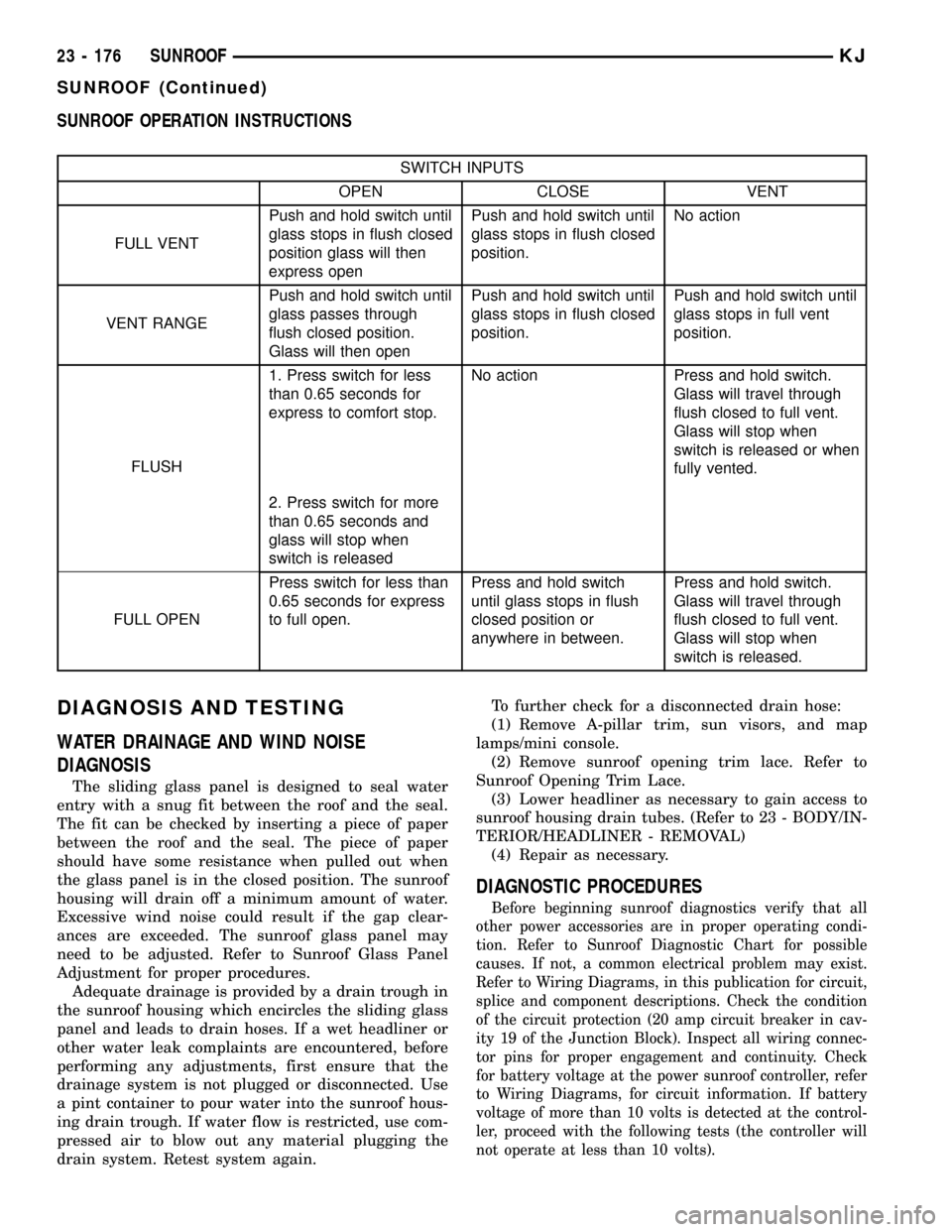
SUNROOF OPERATION INSTRUCTIONS
SWITCH INPUTS
OPEN CLOSE VENT
FULL VENTPush and hold switch until
glass stops in flush closed
position glass will then
express openPush and hold switch until
glass stops in flush closed
position.No action
VENT RANGEPush and hold switch until
glass passes through
flush closed position.
Glass will then openPush and hold switch until
glass stops in flush closed
position.Push and hold switch until
glass stops in full vent
position.
FLUSH1. Press switch for less
than 0.65 seconds for
express to comfort stop.No action Press and hold switch.
Glass will travel through
flush closed to full vent.
Glass will stop when
switch is released or when
fully vented.
2. Press switch for more
than 0.65 seconds and
glass will stop when
switch is released
FULL OPENPress switch for less than
0.65 seconds for express
to full open.Press and hold switch
until glass stops in flush
closed position or
anywhere in between.Press and hold switch.
Glass will travel through
flush closed to full vent.
Glass will stop when
switch is released.
DIAGNOSIS AND TESTING
WATER DRAINAGE AND WIND NOISE
DIAGNOSIS
The sliding glass panel is designed to seal water
entry with a snug fit between the roof and the seal.
The fit can be checked by inserting a piece of paper
between the roof and the seal. The piece of paper
should have some resistance when pulled out when
the glass panel is in the closed position. The sunroof
housing will drain off a minimum amount of water.
Excessive wind noise could result if the gap clear-
ances are exceeded. The sunroof glass panel may
need to be adjusted. Refer to Sunroof Glass Panel
Adjustment for proper procedures.
Adequate drainage is provided by a drain trough in
the sunroof housing which encircles the sliding glass
panel and leads to drain hoses. If a wet headliner or
other water leak complaints are encountered, before
performing any adjustments, first ensure that the
drainage system is not plugged or disconnected. Use
a pint container to pour water into the sunroof hous-
ing drain trough. If water flow is restricted, use com-
pressed air to blow out any material plugging the
drain system. Retest system again.To further check for a disconnected drain hose:
(1) Remove A-pillar trim, sun visors, and map
lamps/mini console.
(2) Remove sunroof opening trim lace. Refer to
Sunroof Opening Trim Lace.
(3) Lower headliner as necessary to gain access to
sunroof housing drain tubes. (Refer to 23 - BODY/IN-
TERIOR/HEADLINER - REMOVAL)
(4) Repair as necessary.
DIAGNOSTIC PROCEDURES
Before beginning sunroof diagnostics verify that all
other power accessories are in proper operating condi-
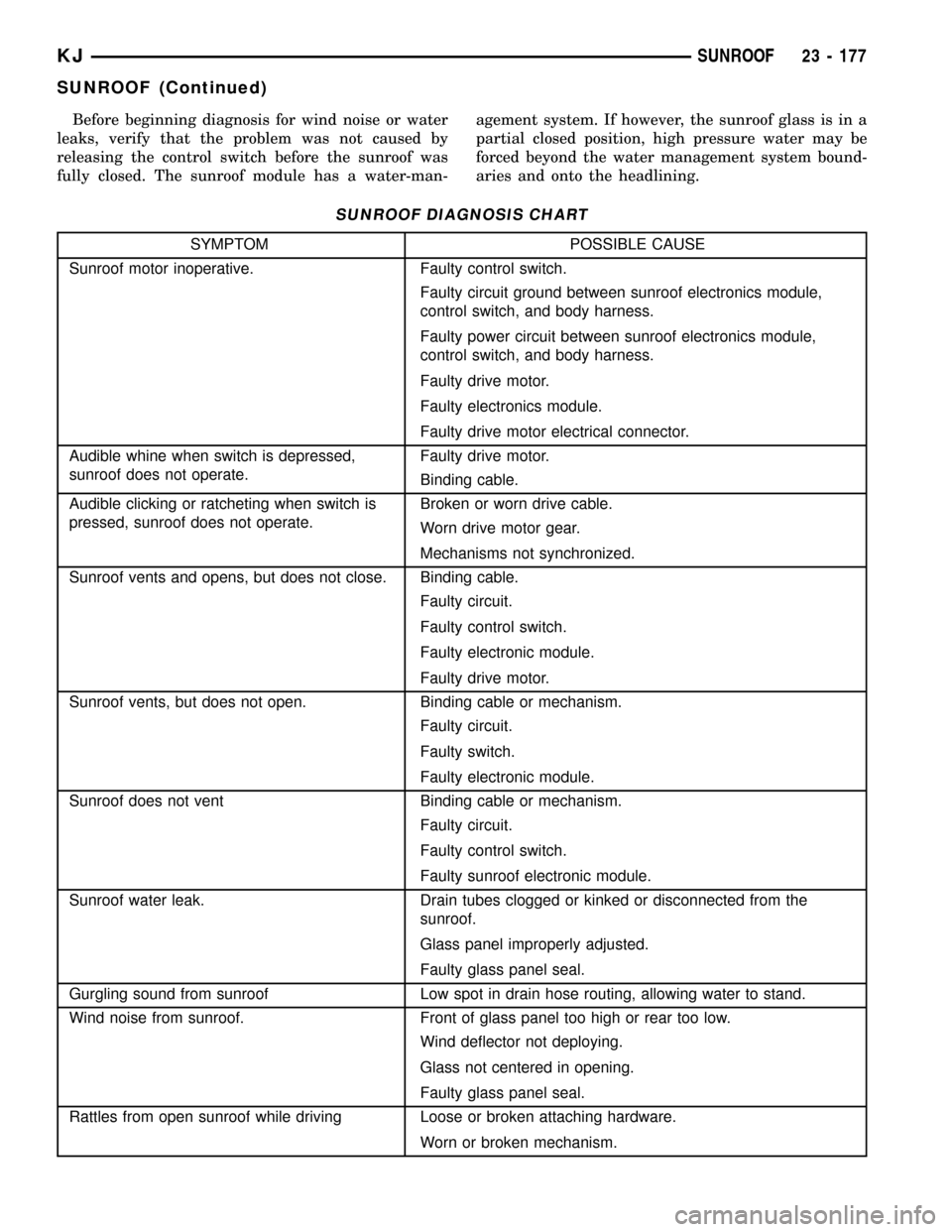
tion. Refer to Sunroof Diagnostic Chart for possible
causes. If not, a common electrical problem may exist.
Refer to Wiring Diagrams, in this publication for circuit,
splice and component descriptions. Check the condition
of the circuit protection (20 amp circuit breaker in cav-
ity 19 of the Junction Block). Inspect all wiring connec-
tor pins for proper engagement and continuity. Check
for battery voltage at the power sunroof controller, refer
to Wiring Diagrams, for circuit information. If battery
voltage of more than 10 volts is detected at the control-
ler, proceed with the following tests (the controller will
not operate at less than 10 volts).
23 - 176 SUNROOFKJ
SUNROOF (Continued)
Page 1642 of 1803

Before beginning diagnosis for wind noise or water
leaks, verify that the problem was not caused by
releasing the control switch before the sunroof was
fully closed. The sunroof module has a water-man-agement system. If however, the sunroof glass is in a
partial closed position, high pressure water may be
forced beyond the water management system bound-
aries and onto the headlining.
SUNROOF DIAGNOSIS CHART
SYMPTOM POSSIBLE CAUSE
Sunroof motor inoperative. Faulty control switch.
Faulty circuit ground between sunroof electronics module,
control switch, and body harness.
Faulty power circuit between sunroof electronics module,
control switch, and body harness.
Faulty drive motor.
Faulty electronics module.
Faulty drive motor electrical connector.
Audible whine when switch is depressed,
sunroof does not operate.Faulty drive motor.
Binding cable.
Audible clicking or ratcheting when switch is
pressed, sunroof does not operate.Broken or worn drive cable.
Worn drive motor gear.
Mechanisms not synchronized.
Sunroof vents and opens, but does not close. Binding cable.
Faulty circuit.
Faulty control switch.
Faulty electronic module.
Faulty drive motor.
Sunroof vents, but does not open. Binding cable or mechanism.
Faulty circuit.
Faulty switch.
Faulty electronic module.
Sunroof does not vent Binding cable or mechanism.
Faulty circuit.
Faulty control switch.
Faulty sunroof electronic module.
Sunroof water leak. Drain tubes clogged or kinked or disconnected from the
sunroof.
Glass panel improperly adjusted.
Faulty glass panel seal.
Gurgling sound from sunroof Low spot in drain hose routing, allowing water to stand.
Wind noise from sunroof. Front of glass panel too high or rear too low.
Wind deflector not deploying.
Glass not centered in opening.
Faulty glass panel seal.
Rattles from open sunroof while driving Loose or broken attaching hardware.
Worn or broken mechanism.
KJSUNROOF 23 - 177
SUNROOF (Continued)