2002 JEEP LIBERTY tow
[x] Cancel search: towPage 1152 of 1803
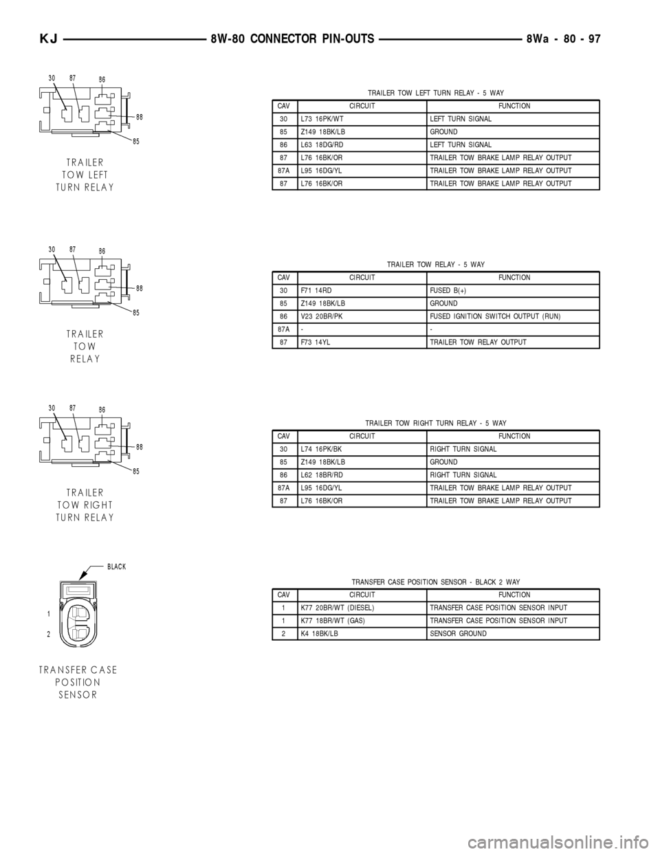
TRAILER TOW LEFT TURN RELAY-5WAY
CAV CIRCUIT FUNCTION
30 L73 16PK/WT LEFT TURN SIGNAL
85 Z149 18BK/LB GROUND
86 L63 18DG/RD LEFT TURN SIGNAL
87 L76 16BK/OR TRAILER TOW BRAKE LAMP RELAY OUTPUT
87A L95 16DG/YL TRAILER TOW BRAKE LAMP RELAY OUTPUT
87 L76 16BK/OR TRAILER TOW BRAKE LAMP RELAY OUTPUT
TRAILER TOW RELAY-5WAY
CAV CIRCUIT FUNCTION
30 F71 14RD FUSED B(+)
85 Z149 18BK/LB GROUND
86 V23 20BR/PK FUSED IGNITION SWITCH OUTPUT (RUN)
87A - -
87 F73 14YL TRAILER TOW RELAY OUTPUT
TRAILER TOW RIGHT TURN RELAY-5WAY
CAV CIRCUIT FUNCTION
30 L74 16PK/BK RIGHT TURN SIGNAL
85 Z149 18BK/LB GROUND
86 L62 18BR/RD RIGHT TURN SIGNAL
87A L95 16DG/YL TRAILER TOW BRAKE LAMP RELAY OUTPUT
87 L76 16BK/OR TRAILER TOW BRAKE LAMP RELAY OUTPUT
TRANSFER CASE POSITION SENSOR - BLACK 2 WAY
CAV CIRCUIT FUNCTION
1 K77 20BR/WT (DIESEL) TRANSFER CASE POSITION SENSOR INPUT
1 K77 18BR/WT (GAS) TRANSFER CASE POSITION SENSOR INPUT
2 K4 18BK/LB SENSOR GROUND
KJ8W-80 CONNECTOR PIN-OUTS8Wa-80-97
Page 1164 of 1803
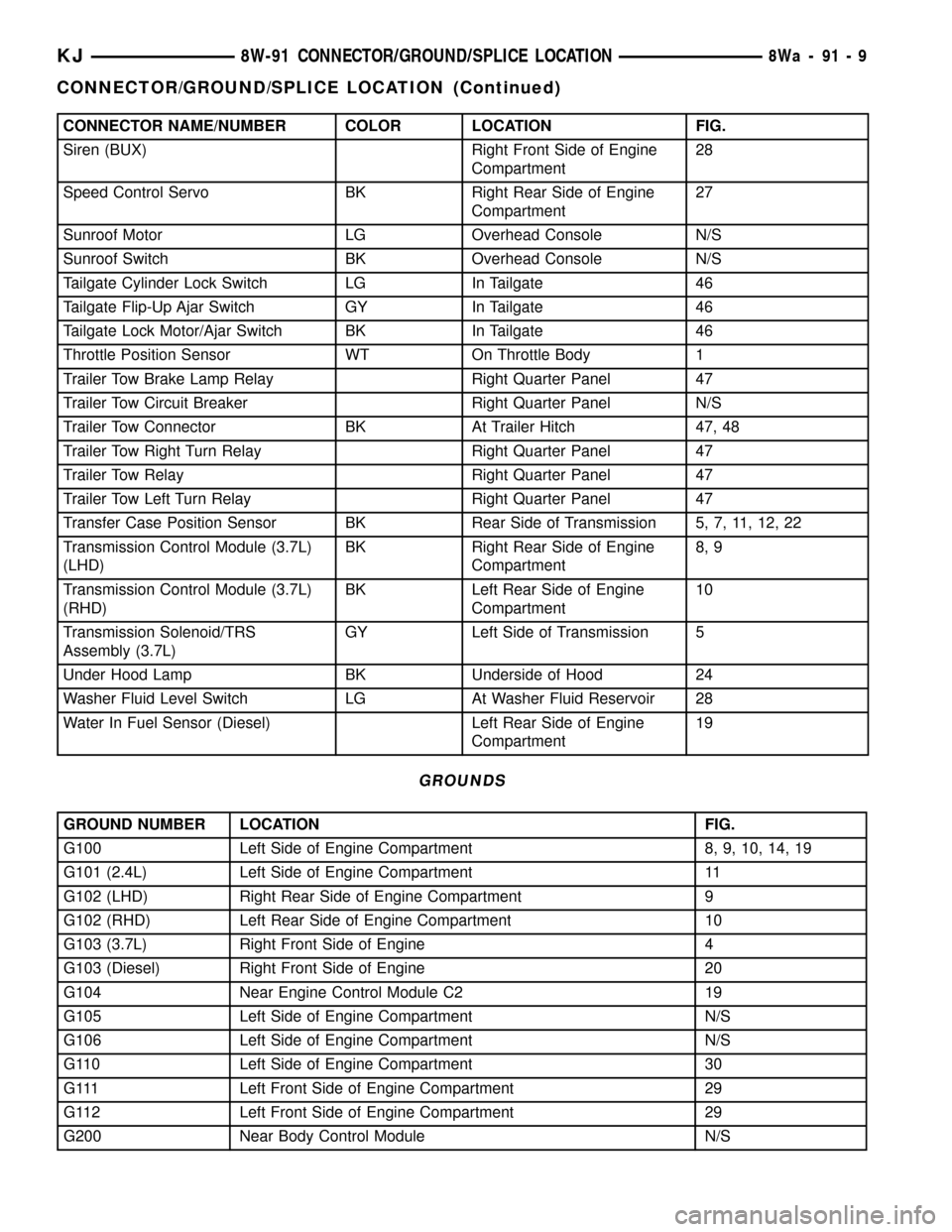
CONNECTOR NAME/NUMBER COLOR LOCATION FIG.
Siren (BUX) Right Front Side of Engine
Compartment28
Speed Control Servo BK Right Rear Side of Engine
Compartment27
Sunroof Motor LG Overhead Console N/S
Sunroof Switch BK Overhead Console N/S
Tailgate Cylinder Lock Switch LG In Tailgate 46
Tailgate Flip-Up Ajar Switch GY In Tailgate 46
Tailgate Lock Motor/Ajar Switch BK In Tailgate 46
Throttle Position Sensor WT On Throttle Body 1
Trailer Tow Brake Lamp Relay Right Quarter Panel 47
Trailer Tow Circuit Breaker Right Quarter Panel N/S
Trailer Tow Connector BK At Trailer Hitch 47, 48
Trailer Tow Right Turn Relay Right Quarter Panel 47
Trailer Tow Relay Right Quarter Panel 47
Trailer Tow Left Turn Relay Right Quarter Panel 47
Transfer Case Position Sensor BK Rear Side of Transmission 5, 7, 11, 12, 22
Transmission Control Module (3.7L)
(LHD)BK Right Rear Side of Engine
Compartment8, 9
Transmission Control Module (3.7L)
(RHD)BK Left Rear Side of Engine
Compartment10
Transmission Solenoid/TRS
Assembly (3.7L)GY Left Side of Transmission 5
Under Hood Lamp BK Underside of Hood 24
Washer Fluid Level Switch LG At Washer Fluid Reservoir 28
Water In Fuel Sensor (Diesel) Left Rear Side of Engine
Compartment19
GROUNDS
GROUND NUMBER LOCATION FIG.
G100 Left Side of Engine Compartment 8, 9, 10, 14, 19
G101 (2.4L) Left Side of Engine Compartment 11
G102 (LHD) Right Rear Side of Engine Compartment 9
G102 (RHD) Left Rear Side of Engine Compartment 10
G103 (3.7L) Right Front Side of Engine 4
G103 (Diesel) Right Front Side of Engine 20
G104 Near Engine Control Module C2 19
G105 Left Side of Engine Compartment N/S
G106 Left Side of Engine Compartment N/S
G110 Left Side of Engine Compartment 30
G111 Left Front Side of Engine Compartment 29
G112 Left Front Side of Engine Compartment 29
G200 Near Body Control Module N/S
KJ8W-91 CONNECTOR/GROUND/SPLICE LOCATION8Wa-91-9
CONNECTOR/GROUND/SPLICE LOCATION (Continued)
Page 1167 of 1803
SPLICE NUMBER LOCATION FIG.
S216 In T/O for Instrument Cluster N/S
S217 Near T/O for Multifunction Switch C2 N/S
S218 Near T/O for Multifunction Switch C2 N/S
S219 In T/O for Junction Block C3 N/S
S220 In T/O for Junction Block C3 N/S
S221 Near T/O for Left Speed Control Switch N/S
S222 Near T/O for Right Speed Control Switch N/S
S223 Near T/O for Left Remote Radio Switch N/S
S224 Near T/O for Right Remote Radio Switch N/S
S300 (LHD) Near T/O for C309 43
S300 (RHD) Near T/O for C310 45
S301 In T/O For Radio C1 N/S
S302 Near T/O for Rear Power Outlet 45
S303 Near T/O for Shifter Assembly 36
S304 Near T/O for License Lamp 45
S306 (LHD) Near T/O for G315 44
S306 (RHD) In T/O for C319 45
S308 (LHD) Near T/O for C309 43
S308 (RHD) Near T/O for Rear Power Outlet 45
S310 Near T/O for C310 N/S
S312 Near T/O for G315 N/S
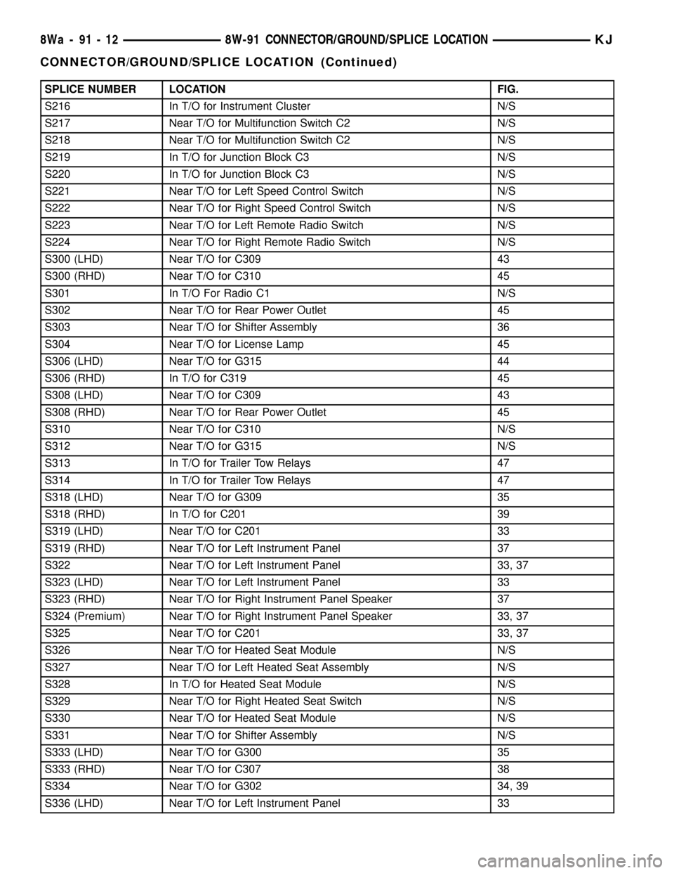
S313 In T/O for Trailer Tow Relays 47
S314 In T/O for Trailer Tow Relays 47
S318 (LHD) Near T/O for G309 35
S318 (RHD) In T/O for C201 39
S319 (LHD) Near T/O for C201 33
S319 (RHD) Near T/O for Left Instrument Panel 37
S322 Near T/O for Left Instrument Panel 33, 37
S323 (LHD) Near T/O for Left Instrument Panel 33
S323 (RHD) Near T/O for Right Instrument Panel Speaker 37
S324 (Premium) Near T/O for Right Instrument Panel Speaker 33, 37
S325 Near T/O for C201 33, 37
S326 Near T/O for Heated Seat Module N/S
S327 Near T/O for Left Heated Seat Assembly N/S
S328 In T/O for Heated Seat Module N/S
S329 Near T/O for Right Heated Seat Switch N/S
S330 Near T/O for Heated Seat Module N/S
S331 Near T/O for Shifter Assembly N/S
S333 (LHD) Near T/O for G300 35
S333 (RHD) Near T/O for C307 38
S334 Near T/O for G302 34, 39
S336 (LHD) Near T/O for Left Instrument Panel 33
8Wa - 91 - 12 8W-91 CONNECTOR/GROUND/SPLICE LOCATIONKJ
CONNECTOR/GROUND/SPLICE LOCATION (Continued)
Page 1168 of 1803
SPLICE NUMBER LOCATION FIG.
S336 (RHD) Near T/O for Right Instrument Panel Speaker 37
S338 Near T/O for C201 33, 37
S340 Near T/O for C201 33
S341 Near T/O for C201 33
S342 (Base) Near T/O for Right Instrument Panel Speaker 33
S344 Near T/O for Right Instrument Panel Speaker 33
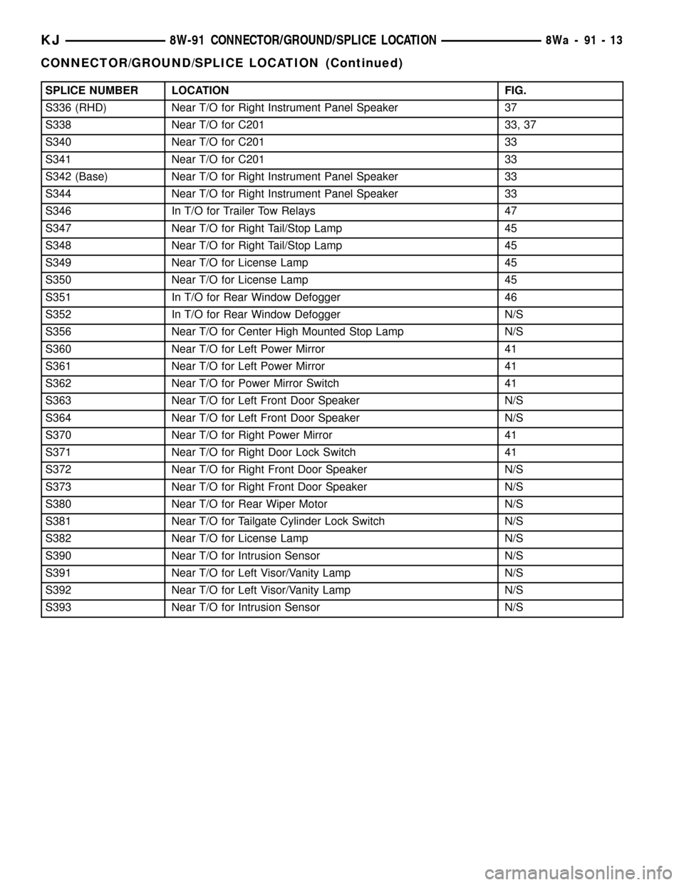
S346 In T/O for Trailer Tow Relays 47
S347 Near T/O for Right Tail/Stop Lamp 45
S348 Near T/O for Right Tail/Stop Lamp 45
S349 Near T/O for License Lamp 45
S350 Near T/O for License Lamp 45
S351 In T/O for Rear Window Defogger 46
S352 In T/O for Rear Window Defogger N/S
S356 Near T/O for Center High Mounted Stop Lamp N/S
S360 Near T/O for Left Power Mirror 41
S361 Near T/O for Left Power Mirror 41
S362 Near T/O for Power Mirror Switch 41
S363 Near T/O for Left Front Door Speaker N/S
S364 Near T/O for Left Front Door Speaker N/S
S370 Near T/O for Right Power Mirror 41
S371 Near T/O for Right Door Lock Switch 41
S372 Near T/O for Right Front Door Speaker N/S
S373 Near T/O for Right Front Door Speaker N/S
S380 Near T/O for Rear Wiper Motor N/S
S381 Near T/O for Tailgate Cylinder Lock Switch N/S
S382 Near T/O for License Lamp N/S
S390 Near T/O for Intrusion Sensor N/S
S391 Near T/O for Left Visor/Vanity Lamp N/S
S392 Near T/O for Left Visor/Vanity Lamp N/S
S393 Near T/O for Intrusion Sensor N/S
KJ8W-91 CONNECTOR/GROUND/SPLICE LOCATION8Wa-91-13
CONNECTOR/GROUND/SPLICE LOCATION (Continued)
Page 1213 of 1803
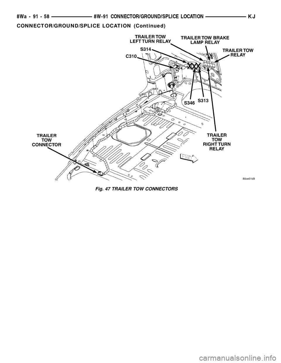
Fig. 47 TRAILER TOW CONNECTORS
8Wa - 91 - 58 8W-91 CONNECTOR/GROUND/SPLICE LOCATIONKJ
CONNECTOR/GROUND/SPLICE LOCATION (Continued)
Page 1240 of 1803
NOTE: When the camshaft is removed the rocker
arms may slide downward, mark the rocker arms
before removing camshaft.
(9) Remove the camshaft bearing caps and the
camshaft.
INSTALLATION
(1) Lubricate camshaft journals with clean engine
oil.
NOTE: Position the left side camshaft so that the
camshaft sprocket dowel is near the 1 o'clock posi-
tion, This will place the camshaft at the neutral
position easing the installation of the camshaft
bearing caps.
(2) Position the camshaft into the cylinder head.
(3) Install the camshaft bearing caps, hand tighten
the retaining bolts.
NOTE: Caps should be installed so that the
stamped numbers on the caps are in numerical
order, ( 1 thru 4 ) from the front to the rear of the
engine. All caps should be installed so that the
stamped arrows on the caps point toward the front
of the engine.
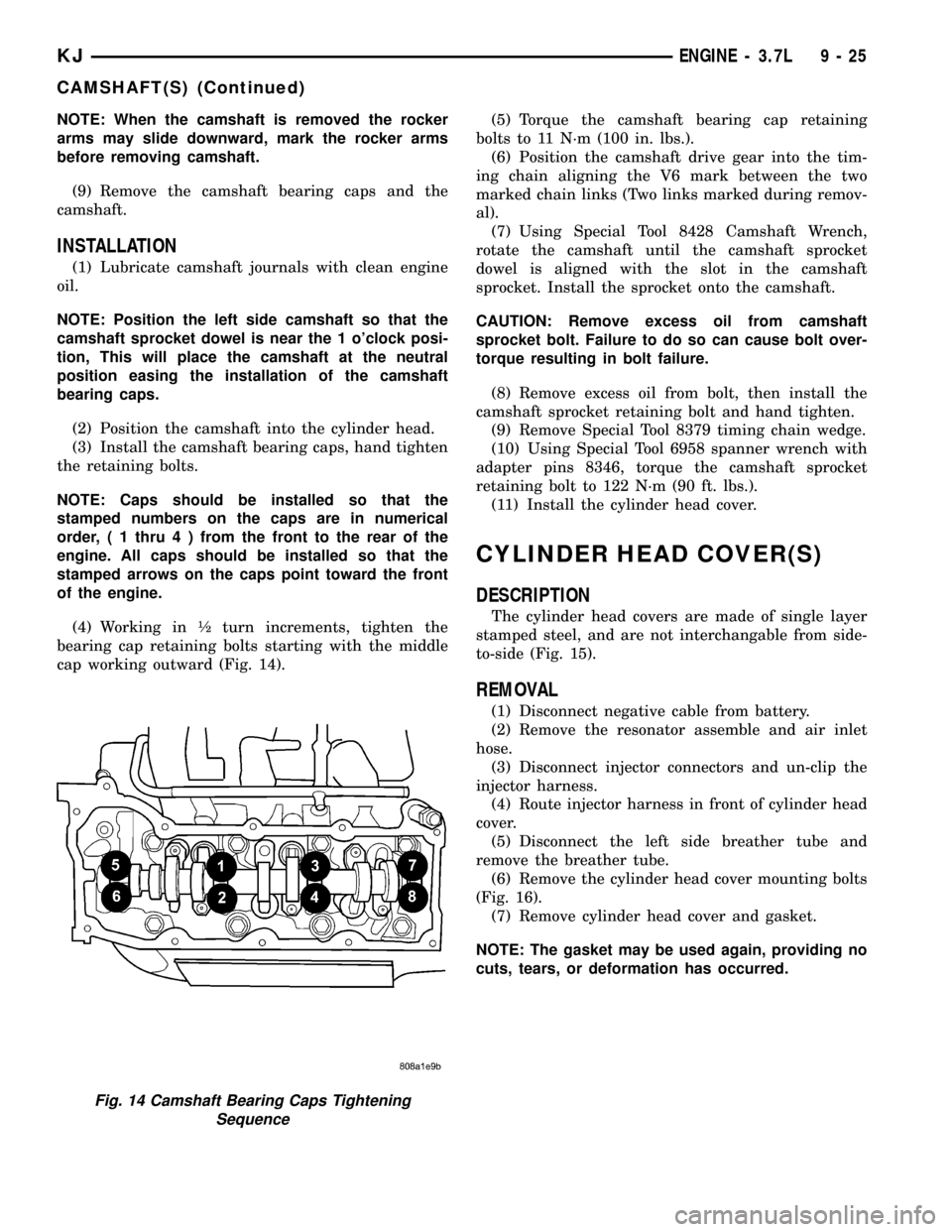
(4) Working in ó turn increments, tighten the
bearing cap retaining bolts starting with the middle
cap working outward (Fig. 14).(5) Torque the camshaft bearing cap retaining
bolts to 11 N´m (100 in. lbs.).
(6) Position the camshaft drive gear into the tim-
ing chain aligning the V6 mark between the two
marked chain links (Two links marked during remov-
al).
(7) Using Special Tool 8428 Camshaft Wrench,
rotate the camshaft until the camshaft sprocket
dowel is aligned with the slot in the camshaft
sprocket. Install the sprocket onto the camshaft.
CAUTION: Remove excess oil from camshaft
sprocket bolt. Failure to do so can cause bolt over-
torque resulting in bolt failure.
(8) Remove excess oil from bolt, then install the
camshaft sprocket retaining bolt and hand tighten.
(9) Remove Special Tool 8379 timing chain wedge.
(10) Using Special Tool 6958 spanner wrench with
adapter pins 8346, torque the camshaft sprocket
retaining bolt to 122 N´m (90 ft. lbs.).
(11) Install the cylinder head cover.
CYLINDER HEAD COVER(S)
DESCRIPTION
The cylinder head covers are made of single layer
stamped steel, and are not interchangable from side-
to-side (Fig. 15).
REMOVAL
(1) Disconnect negative cable from battery.
(2) Remove the resonator assemble and air inlet
hose.
(3) Disconnect injector connectors and un-clip the
injector harness.
(4) Route injector harness in front of cylinder head
cover.
(5) Disconnect the left side breather tube and
remove the breather tube.
(6) Remove the cylinder head cover mounting bolts
(Fig. 16).
(7) Remove cylinder head cover and gasket.
NOTE: The gasket may be used again, providing no
cuts, tears, or deformation has occurred.
Fig. 14 Camshaft Bearing Caps Tightening
Sequence
KJENGINE - 3.7L 9 - 25
CAMSHAFT(S) (Continued)
Page 1248 of 1803
(19) Install oil fill housing onto cylinder head.
(20) Refill the cooling system.
(21) Raise the vehicle.
(22) Install the exhaust pipe onto the right
exhaust manifold.
(23) Lower the vehicle.
(24) Reconnect battery negitive cable.
(25) Start the engine and check for leaks.
CAMSHAFT(S)
DESCRIPTION
The camshafts consist of powdered metal steel
lobes which are sinter-bonded to a steel tube. Four
bearing journals are machined into the camshaft.
Camshaft end play is controlled by two thrust walls
that border the nose piece journal. Engine oil enters
the hollow camshafts at the third journal and lubri-
cates every intake lobe rocker through a drilled pas-
sage in the intake lobe.
REMOVAL
CAUTION: When the timing chain is removed and
the cylinder heads are still installed, DO NOT force-
fully rotate the camshafts or crankshaft indepen-
dently of each other. Severe valve and/or piston
damage can occur.
CAUTION: When removing the cam sprocket, timing
chains or camshaft, Failure to use special tool 8379
will result in hydraulic tensioner ratchet over exten-
sion, Requiring timing chain cover removal to re-set
the tensioner ratchet.
(1) Remove the cylinder head cover. Refer to CYL-
INDER HEAD COVER in this section.
(2) Set engine to TDC cylinder #1, camshaft
sprocket V6 marks at the 12 o'clock position.
(3) Mark one link on the secondary timing chain
on both sides of the V6 mark on the camshaft
sprocket to aid in installation.
CAUTION: Do not hold or pry on the camshaft tar-
get wheel for any reason, Severe damage will occur
to the target wheel. A damaged target wheel could
cause a vehicle no start condition.
(4) Loosen butDO NOTremove the camshaft
sprocket retaining bolt. Leave bolt snug against
sprocket.
NOTE: The timing chain tensioners must be
secured prior to removing the camshaft sprockets.
Failure to secure tensioners will allow the tension-ers to extend, requiring timing chain cover removal
in order to reset tensioners.
CAUTION: Do not force wedge past the narrowest
point between the chain strands. Damage to the
tensioners may occur.
(5) Position Special Tool 8379 timing chain wedge
between the timing chain strands. Tap the tool to
securely wedge the timing chain against the ten-
sioner arm and guide.
(6) Remove the camshaft position sensor.
(7) Hold the camshaft with Special Tool 8428 Cam-
shaft Wrench, while removing the camshaft sprocket
bolt and sprocket.
(8) Starting at the outside working inward, loosen
the camshaft bearing cap retaining bolts 1/2 turn at
a time. Repeat until all load is off the bearing caps.
CAUTION: DO NOT STAMP OR STRIKE THE CAM-
SHAFT BEARING CAPS. SEVERE DAMAGE WILL
OCCUR TO THE BEARING CAPS.
NOTE: When the camshaft is removed the rocker
arms may slide downward, mark the rocker arms
before removing camshaft.
(9) Remove the camshaft bearing caps and the
camshaft.
INSTALLATION
(1) Lubricate camshaft journals with clean engine
oil.
NOTE: Position the right side camshaft so that the
camshaft sprocket dowel is near the 10 o'clock
position, This will place the camshaft at the neutral
position easing the installation of the camshaft
bearing caps.
(2) Position the camshaft into the cylinder head.
(3) Install the camshaft bearing caps, hand tighten
the retaining bolts.
NOTE: Caps should be installed so that the
stamped numbers on the caps are in numerical
order, ( 1 thru 4 ) from the front to the rear of the
engine. All caps should be installed so that the
stamped arrows on the caps point toward the front
of the engine.
(4) Working in 1/2 turn increments, tighten the
bearing cap retaining bolts starting with the middle
cap working outward (Fig. 23).
(5) Torque the camshaft bearing cap retaining
bolts to 11 N´m (100 in. lbs.).
KJENGINE - 3.7L 9 - 33
CYLINDER HEAD - RIGHT (Continued)
Page 1254 of 1803
ENGINE BLOCK
DESCRIPTION
The cylinder block is made of cast iron. The block
is a closed deck design with the left bank forward. To
provide high rigidity and improved NVH an
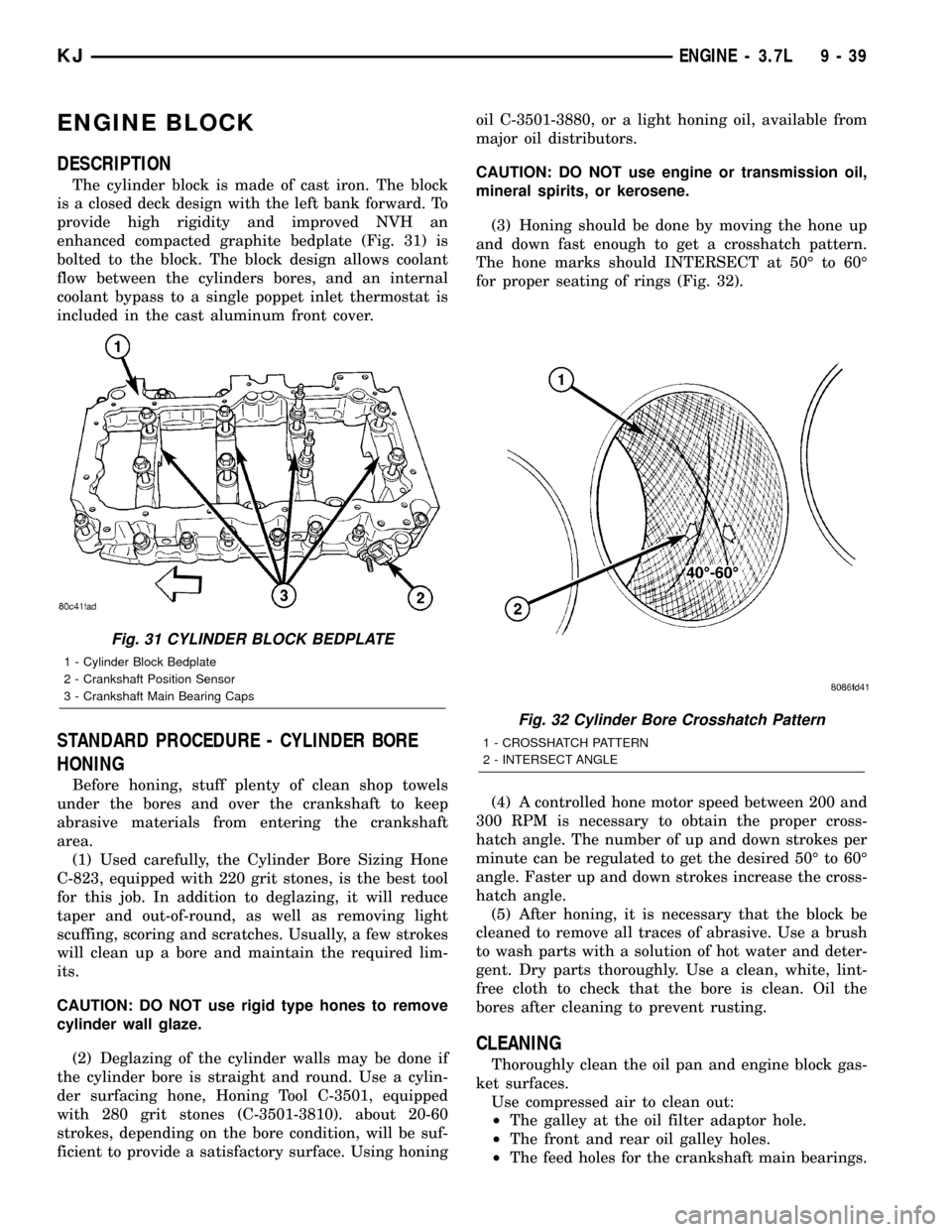
enhanced compacted graphite bedplate (Fig. 31) is
bolted to the block. The block design allows coolant
flow between the cylinders bores, and an internal
coolant bypass to a single poppet inlet thermostat is
included in the cast aluminum front cover.
STANDARD PROCEDURE - CYLINDER BORE
HONING
Before honing, stuff plenty of clean shop towels
under the bores and over the crankshaft to keep
abrasive materials from entering the crankshaft
area.
(1) Used carefully, the Cylinder Bore Sizing Hone
C-823, equipped with 220 grit stones, is the best tool
for this job. In addition to deglazing, it will reduce
taper and out-of-round, as well as removing light
scuffing, scoring and scratches. Usually, a few strokes
will clean up a bore and maintain the required lim-
its.
CAUTION: DO NOT use rigid type hones to remove
cylinder wall glaze.
(2) Deglazing of the cylinder walls may be done if
the cylinder bore is straight and round. Use a cylin-
der surfacing hone, Honing Tool C-3501, equipped
with 280 grit stones (C-3501-3810). about 20-60
strokes, depending on the bore condition, will be suf-
ficient to provide a satisfactory surface. Using honingoil C-3501-3880, or a light honing oil, available from
major oil distributors.
CAUTION: DO NOT use engine or transmission oil,
mineral spirits, or kerosene.
(3) Honing should be done by moving the hone up
and down fast enough to get a crosshatch pattern.
The hone marks should INTERSECT at 50É to 60É
for proper seating of rings (Fig. 32).
(4) A controlled hone motor speed between 200 and
300 RPM is necessary to obtain the proper cross-
hatch angle. The number of up and down strokes per
minute can be regulated to get the desired 50É to 60É
angle. Faster up and down strokes increase the cross-
hatch angle.
(5) After honing, it is necessary that the block be
cleaned to remove all traces of abrasive. Use a brush
to wash parts with a solution of hot water and deter-
gent. Dry parts thoroughly. Use a clean, white, lint-
free cloth to check that the bore is clean. Oil the
bores after cleaning to prevent rusting.
CLEANING
Thoroughly clean the oil pan and engine block gas-
ket surfaces.
Use compressed air to clean out:
²The galley at the oil filter adaptor hole.
²The front and rear oil galley holes.
²The feed holes for the crankshaft main bearings.
Fig. 31 CYLINDER BLOCK BEDPLATE
1 - Cylinder Block Bedplate
2 - Crankshaft Position Sensor
3 - Crankshaft Main Bearing Caps
Fig. 32 Cylinder Bore Crosshatch Pattern
1 - CROSSHATCH PATTERN
2 - INTERSECT ANGLE
KJENGINE - 3.7L 9 - 39