2002 JEEP LIBERTY tow
[x] Cancel search: towPage 1408 of 1803
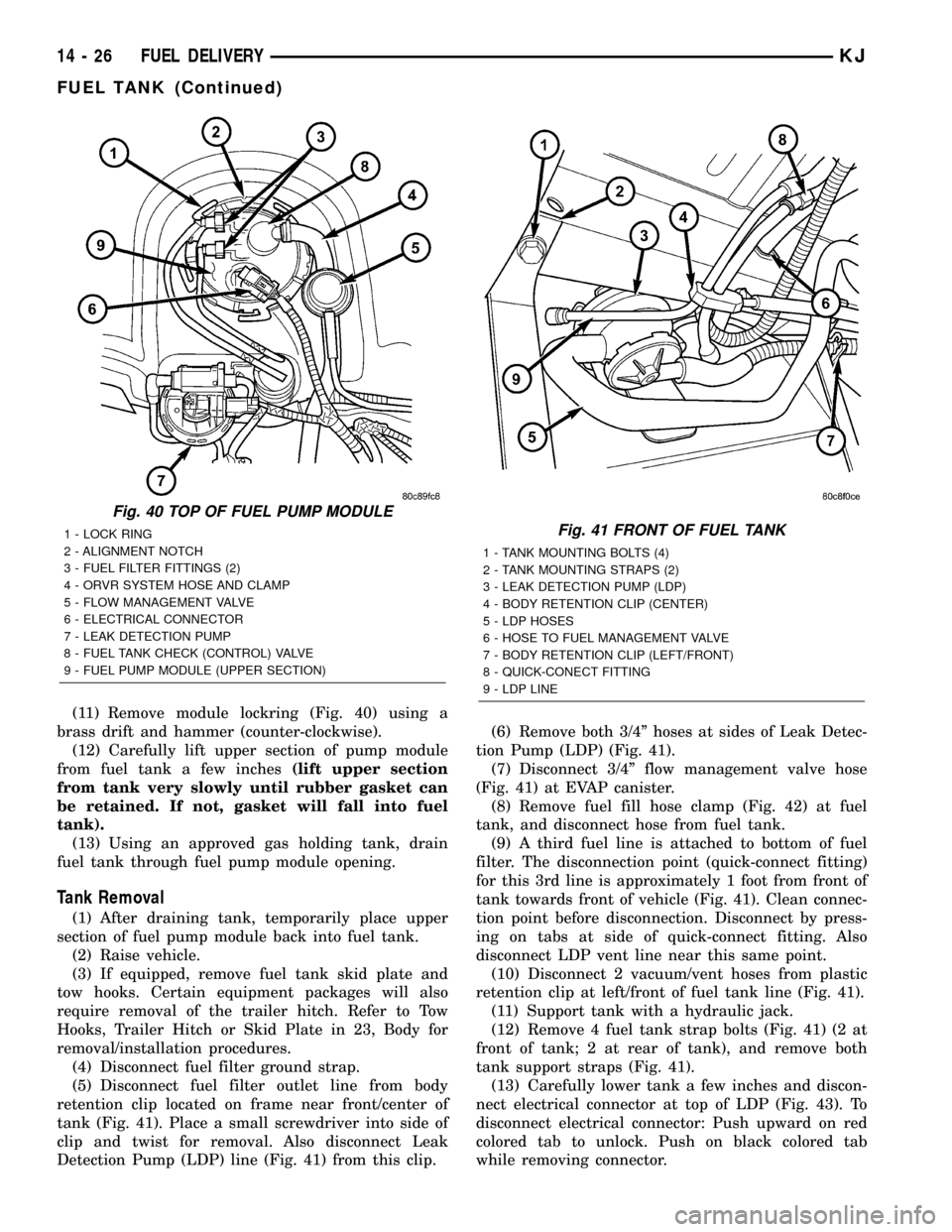
(11) Remove module lockring (Fig. 40) using a
brass drift and hammer (counter-clockwise).
(12) Carefully lift upper section of pump module
from fuel tank a few inches(lift upper section
from tank very slowly until rubber gasket can
be retained. If not, gasket will fall into fuel
tank).
(13) Using an approved gas holding tank, drain
fuel tank through fuel pump module opening.
Tank Removal
(1) After draining tank, temporarily place upper
section of fuel pump module back into fuel tank.
(2) Raise vehicle.
(3) If equipped, remove fuel tank skid plate and
tow hooks. Certain equipment packages will also
require removal of the trailer hitch. Refer to Tow
Hooks, Trailer Hitch or Skid Plate in 23, Body for
removal/installation procedures.
(4) Disconnect fuel filter ground strap.
(5) Disconnect fuel filter outlet line from body
retention clip located on frame near front/center of
tank (Fig. 41). Place a small screwdriver into side of
clip and twist for removal. Also disconnect Leak
Detection Pump (LDP) line (Fig. 41) from this clip.(6) Remove both 3/4º hoses at sides of Leak Detec-
tion Pump (LDP) (Fig. 41).
(7) Disconnect 3/4º flow management valve hose
(Fig. 41) at EVAP canister.
(8) Remove fuel fill hose clamp (Fig. 42) at fuel
tank, and disconnect hose from fuel tank.
(9) A third fuel line is attached to bottom of fuel
filter. The disconnection point (quick-connect fitting)
for this 3rd line is approximately 1 foot from front of
tank towards front of vehicle (Fig. 41). Clean connec-
tion point before disconnection. Disconnect by press-
ing on tabs at side of quick-connect fitting. Also
disconnect LDP vent line near this same point.
(10) Disconnect 2 vacuum/vent hoses from plastic
retention clip at left/front of fuel tank line (Fig. 41).
(11) Support tank with a hydraulic jack.
(12) Remove 4 fuel tank strap bolts (Fig. 41) (2 at
front of tank; 2 at rear of tank), and remove both
tank support straps (Fig. 41).
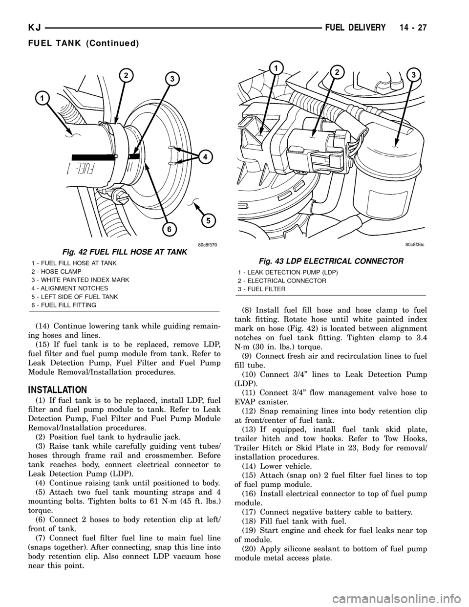
(13) Carefully lower tank a few inches and discon-
nect electrical connector at top of LDP (Fig. 43). To
disconnect electrical connector: Push upward on red
colored tab to unlock. Push on black colored tab
while removing connector.
Fig. 40 TOP OF FUEL PUMP MODULE
1 - LOCK RING
2 - ALIGNMENT NOTCH
3 - FUEL FILTER FITTINGS (2)
4 - ORVR SYSTEM HOSE AND CLAMP
5 - FLOW MANAGEMENT VALVE
6 - ELECTRICAL CONNECTOR
7 - LEAK DETECTION PUMP
8 - FUEL TANK CHECK (CONTROL) VALVE
9 - FUEL PUMP MODULE (UPPER SECTION)Fig. 41 FRONT OF FUEL TANK
1 - TANK MOUNTING BOLTS (4)
2 - TANK MOUNTING STRAPS (2)
3 - LEAK DETECTION PUMP (LDP)
4 - BODY RETENTION CLIP (CENTER)
5 - LDP HOSES
6 - HOSE TO FUEL MANAGEMENT VALVE
7 - BODY RETENTION CLIP (LEFT/FRONT)
8 - QUICK-CONECT FITTING
9 - LDP LINE
14 - 26 FUEL DELIVERYKJ
FUEL TANK (Continued)
Page 1409 of 1803
(14) Continue lowering tank while guiding remain-
ing hoses and lines.
(15) If fuel tank is to be replaced, remove LDP,
fuel filter and fuel pump module from tank. Refer to
Leak Detection Pump, Fuel Filter and Fuel Pump
Module Removal/Installation procedures.
INSTALLATION
(1) If fuel tank is to be replaced, install LDP, fuel
filter and fuel pump module to tank. Refer to Leak
Detection Pump, Fuel Filter and Fuel Pump Module
Removal/Installation procedures.
(2) Position fuel tank to hydraulic jack.
(3) Raise tank while carefully guiding vent tubes/
hoses through frame rail and crossmember. Before
tank reaches body, connect electrical connector to
Leak Detection Pump (LDP).
(4) Continue raising tank until positioned to body.
(5) Attach two fuel tank mounting straps and 4
mounting bolts. Tighten bolts to 61 N´m (45 ft. lbs.)
torque.
(6) Connect 2 hoses to body retention clip at left/
front of tank.
(7) Connect fuel filter fuel line to main fuel line
(snaps together). After connecting, snap this line into
body retention clip. Also connect LDP vacuum hose
near this point.(8) Install fuel fill hose and hose clamp to fuel
tank fitting. Rotate hose until white painted index
mark on hose (Fig. 42) is located between alignment
notches on fuel tank fitting. Tighten clamp to 3.4
N´m (30 in. lbs.) torque.
(9) Connect fresh air and recirculation lines to fuel
fill tube.
(10) Connect 3/4º lines to Leak Detection Pump
(LDP).
(11) Connect 3/4º flow management valve hose to
EVAP canister.
(12) Snap remaining lines into body retention clip
at front/center of fuel tank.
(13) If equipped, install fuel tank skid plate,
trailer hitch and tow hooks. Refer to Tow Hooks,
Trailer Hitch or Skid Plate in 23, Body for removal/
installation procedures.
(14) Lower vehicle.
(15) Attach (snap on) 2 fuel filter fuel lines to top
of fuel pump module.
(16) Install electrical connector to top of fuel pump
module.
(17) Connect negative battery cable to battery.
(18) Fill fuel tank with fuel.
(19) Start engine and check for fuel leaks near top
of module.
(20) Apply silicone sealant to bottom of fuel pump
module metal access plate.
Fig. 42 FUEL FILL HOSE AT TANK
1 - FUEL FILL HOSE AT TANK
2 - HOSE CLAMP
3 - WHITE PAINTED INDEX MARK
4 - ALIGNMENT NOTCHES
5 - LEFT SIDE OF FUEL TANK
6 - FUEL FILL FITTINGFig. 43 LDP ELECTRICAL CONNECTOR
1 - LEAK DETECTION PUMP (LDP)
2 - ELECTRICAL CONNECTOR
3 - FUEL FILTER
KJFUEL DELIVERY 14 - 27
FUEL TANK (Continued)
Page 1427 of 1803
THROTTLE CONTROL CABLE
REMOVAL
2.4L
CAUTION: Be careful not to damage or kink the
cable core wire (within the cable sheathing) while
servicing accelerator pedal or throttle cable.
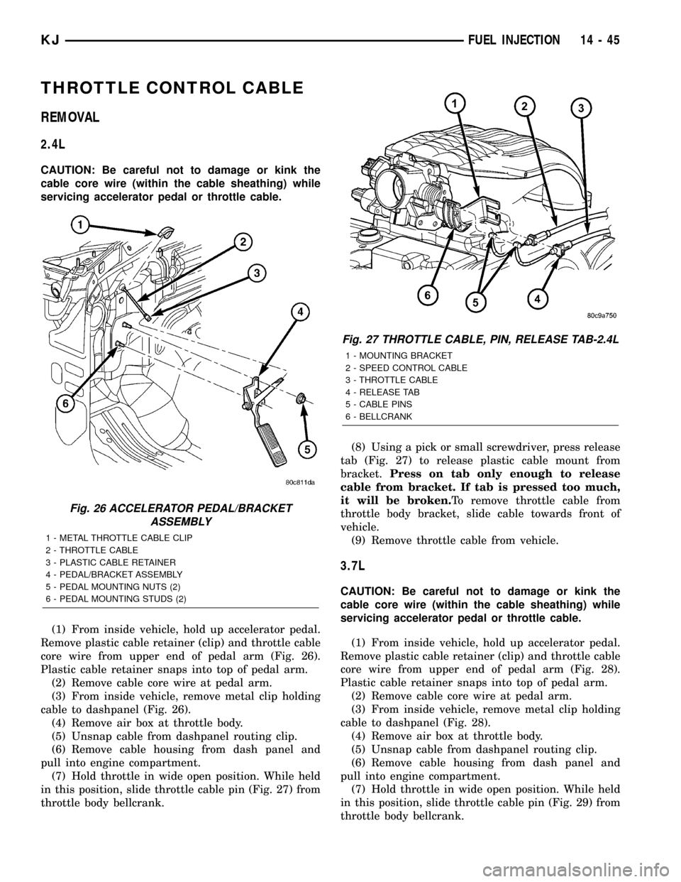
(1) From inside vehicle, hold up accelerator pedal.
Remove plastic cable retainer (clip) and throttle cable
core wire from upper end of pedal arm (Fig. 26).
Plastic cable retainer snaps into top of pedal arm.
(2) Remove cable core wire at pedal arm.
(3) From inside vehicle, remove metal clip holding
cable to dashpanel (Fig. 26).
(4) Remove air box at throttle body.
(5) Unsnap cable from dashpanel routing clip.
(6) Remove cable housing from dash panel and
pull into engine compartment.
(7) Hold throttle in wide open position. While held
in this position, slide throttle cable pin (Fig. 27) from
throttle body bellcrank.(8) Using a pick or small screwdriver, press release
tab (Fig. 27) to release plastic cable mount from
bracket.Press on tab only enough to release
cable from bracket. If tab is pressed too much,
it will be broken.To remove throttle cable from
throttle body bracket, slide cable towards front of
vehicle.
(9) Remove throttle cable from vehicle.
3.7L
CAUTION: Be careful not to damage or kink the
cable core wire (within the cable sheathing) while
servicing accelerator pedal or throttle cable.
(1) From inside vehicle, hold up accelerator pedal.
Remove plastic cable retainer (clip) and throttle cable
core wire from upper end of pedal arm (Fig. 28).
Plastic cable retainer snaps into top of pedal arm.
(2) Remove cable core wire at pedal arm.
(3) From inside vehicle, remove metal clip holding
cable to dashpanel (Fig. 28).
(4) Remove air box at throttle body.
(5) Unsnap cable from dashpanel routing clip.
(6) Remove cable housing from dash panel and
pull into engine compartment.
(7) Hold throttle in wide open position. While held
in this position, slide throttle cable pin (Fig. 29) from
throttle body bellcrank.
Fig. 26 ACCELERATOR PEDAL/BRACKET
ASSEMBLY
1 - METAL THROTTLE CABLE CLIP
2 - THROTTLE CABLE
3 - PLASTIC CABLE RETAINER
4 - PEDAL/BRACKET ASSEMBLY
5 - PEDAL MOUNTING NUTS (2)
6 - PEDAL MOUNTING STUDS (2)
Fig. 27 THROTTLE CABLE, PIN, RELEASE TAB-2.4L
1 - MOUNTING BRACKET
2 - SPEED CONTROL CABLE
3 - THROTTLE CABLE
4 - RELEASE TAB
5 - CABLE PINS
6 - BELLCRANK
KJFUEL INJECTION 14 - 45
Page 1428 of 1803
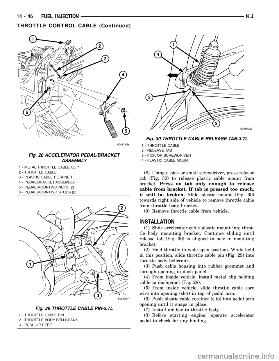
(8) Using a pick or small screwdriver, press release
tab (Fig. 30) to release plastic cable mount from
bracket.Press on tab only enough to release
cable from bracket. If tab is pressed too much,
it will be broken.Slide plastic mount (Fig. 30)
towards right side of vehicle to remove throttle cable
from throttle body bracket.
(9) Remove throttle cable from vehicle.
INSTALLATION
(1) Slide accelerator cable plastic mount into throt-
tle body mounting bracket. Continue sliding until
release tab (Fig. 30) is aligned to hole in mounting
bracket.
(2) Hold throttle in wide open position. While held
in this position, slide throttle cable pin (Fig. 29) into
throttle body bellcrank.
(3) Push cable housing into rubber grommet and
through opening in dash panel.
(4) From inside vehicle, install metal clip holding
cable to dashpanel (Fig. 28).
(5) From inside vehicle, slide throttle cable core
wire into opening (slot) in top of pedal arm.
(6) Push plastic cable retainer (clip) into pedal arm
opening until it snaps in place.
(7) Install air box to throttle body.
(8) Before starting engine, operate accelerator
pedal to check for any binding.
Fig. 28 ACCELERATOR PEDAL/BRACKET
ASSEMBLY
1 - METAL THROTTLE CABLE CLIP
2 - THROTTLE CABLE
3 - PLASTIC CABLE RETAINER
4 - PEDAL/BRACKET ASSEMBLY
5 - PEDAL MOUNTING NUTS (2)
6 - PEDAL MOUNTING STUDS (2)
Fig. 29 THROTTLE CABLE PIN-3.7L
1 - THROTTLE CABLE PIN
2 - THROTTLE BODY BELLCRANK
3 - PUSH UP HERE
Fig. 30 THROTTLE CABLE RELEASE TAB-3.7L
1 - THROTTLE CABLE
2 - RELEASE TAB
3 - PICK OR SCREWDRIVER
4 - PLASTIC CABLE MOUNT
14 - 46 FUEL INJECTIONKJ
THROTTLE CONTROL CABLE (Continued)
Page 1441 of 1803
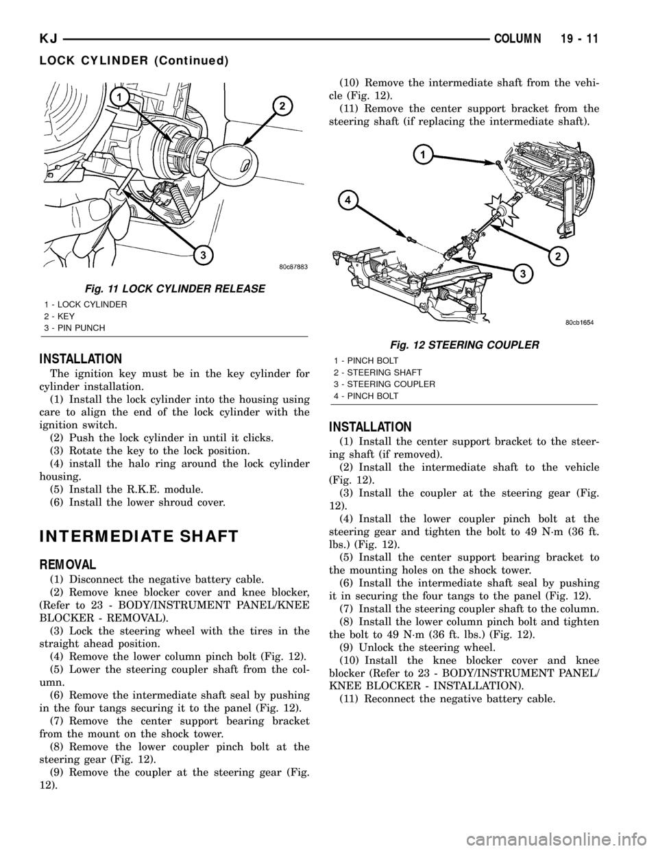
INSTALLATION
The ignition key must be in the key cylinder for
cylinder installation.
(1) Install the lock cylinder into the housing using
care to align the end of the lock cylinder with the
ignition switch.
(2) Push the lock cylinder in until it clicks.
(3) Rotate the key to the lock position.
(4) install the halo ring around the lock cylinder
housing.
(5) Install the R.K.E. module.
(6) Install the lower shroud cover.
INTERMEDIATE SHAFT
REMOVAL
(1) Disconnect the negative battery cable.
(2) Remove knee blocker cover and knee blocker,
(Refer to 23 - BODY/INSTRUMENT PANEL/KNEE
BLOCKER - REMOVAL).
(3) Lock the steering wheel with the tires in the
straight ahead position.
(4) Remove the lower column pinch bolt (Fig. 12).
(5) Lower the steering coupler shaft from the col-
umn.
(6) Remove the intermediate shaft seal by pushing
in the four tangs securing it to the panel (Fig. 12).
(7) Remove the center support bearing bracket
from the mount on the shock tower.
(8) Remove the lower coupler pinch bolt at the
steering gear (Fig. 12).
(9) Remove the coupler at the steering gear (Fig.
12).(10) Remove the intermediate shaft from the vehi-
cle (Fig. 12).
(11) Remove the center support bracket from the
steering shaft (if replacing the intermediate shaft).
INSTALLATION
(1) Install the center support bracket to the steer-
ing shaft (if removed).
(2) Install the intermediate shaft to the vehicle
(Fig. 12).
(3) Install the coupler at the steering gear (Fig.
12).
(4) Install the lower coupler pinch bolt at the
steering gear and tighten the bolt to 49 N´m (36 ft.
lbs.) (Fig. 12).
(5) Install the center support bearing bracket to
the mounting holes on the shock tower.
(6) Install the intermediate shaft seal by pushing
it in securing the four tangs to the panel (Fig. 12).
(7) Install the steering coupler shaft to the column.
(8) Install the lower column pinch bolt and tighten
the bolt to 49 N´m (36 ft. lbs.) (Fig. 12).
(9) Unlock the steering wheel.
(10) Install the knee blocker cover and knee
blocker (Refer to 23 - BODY/INSTRUMENT PANEL/
KNEE BLOCKER - INSTALLATION).
(11) Reconnect the negative battery cable.
Fig. 11 LOCK CYLINDER RELEASE
1 - LOCK CYLINDER
2 - KEY
3 - PIN PUNCH
Fig. 12 STEERING COUPLER
1 - PINCH BOLT
2 - STEERING SHAFT
3 - STEERING COUPLER
4 - PINCH BOLT
KJCOLUMN 19 - 11
LOCK CYLINDER (Continued)
Page 1452 of 1803
(6) Install the serpentine belt (Refer to 7 - COOL-
ING/ACCESSORY DRIVE/DRIVE BELTS - INSTAL-
LATION).
(7) Install the fan shroud.
(8) Install the fan (Refer to 7 - COOLING/EN-
GINE/RADIATOR FAN - INSTALLATION).
(9) Install the radiator crossmember (Refer to 23 -
BODY/EXTERIOR/RADIATOR CROSSMEMBER -
INSTALLATION).
(10) Refill the power steering fluid (Refer to 19 -
STEERING/PUMP - STANDARD PROCEDURE).
INSTALLATION - RETURN HOSE (GEAR TO THE
COOLER)
(1) Install the return hose to the vehicle. (Fig. 7)
(2) Install the return hose mounting bracket bolts
to the front cradle.
(3) Install the return hose at the cooler.
(4) Install the return hose at the gear 28 N´m (21
ft.lbs.).
(5) Install the serpentine belt (Refer to 7 - COOL-
ING/ACCESSORY DRIVE/DRIVE BELTS - INSTAL-
LATION).
(6) Install the fan shroud.
(7) Install the fan (Refer to 7 - COOLING/EN-
GINE/RADIATOR FAN - INSTALLATION).
(8) Install the radiator crossmember (Refer to 23 -
BODY/EXTERIOR/RADIATOR CROSSMEMBER -
INSTALLATION).
(9) Refill the power steering fluid (Refer to 19 -
STEERING/PUMP - STANDARD PROCEDURE).
INSTALLATION - RETURN HOSE (RESERVOIR
TO THE COOLER)
(1) Install the return hose to the vehicle.
(2) Install the return hose to the pump reservoir.
(3) Install the return hose at the cooler.
(4) Refill the power steering fluid (Refer to 19 -
STEERING/PUMP - STANDARD PROCEDURE).
POWER STEERING PRESSURE
SWITCH
DESCRIPTION
A pressure sensing switch is used in the power
steering system. It is mounted on the high-pressure
steering hose. This switch will be used with both
2.4L and 3.7L engines.
OPERATION
The switch is used on both the 2.4L 4±cylinder and
3.7L V-6 engines.
The power steering pressure switch provides an
input to the Powertrain Control Module (PCM). This
input is provided during periods of high steering
pump load and low engine rpm; such as during park-
ing maneuvers. The PCM increases the idle speed
through the Idle Air Control (IAC) motor. This is
done to prevent the engine from stalling under the
increased load.
When steering pump pressure exceeds 3275 kPa
690 kPa (475 psi 100 psi), the Normally Closed
(NC) switch will open and the PCM will increase the
engine idle speed. This will prevent the engine from
stalling.
When pump pressure drops to approximately 1379
kPa (200 psi), the switch circuit will re-close and
engine idle speed will return to its previous setting.
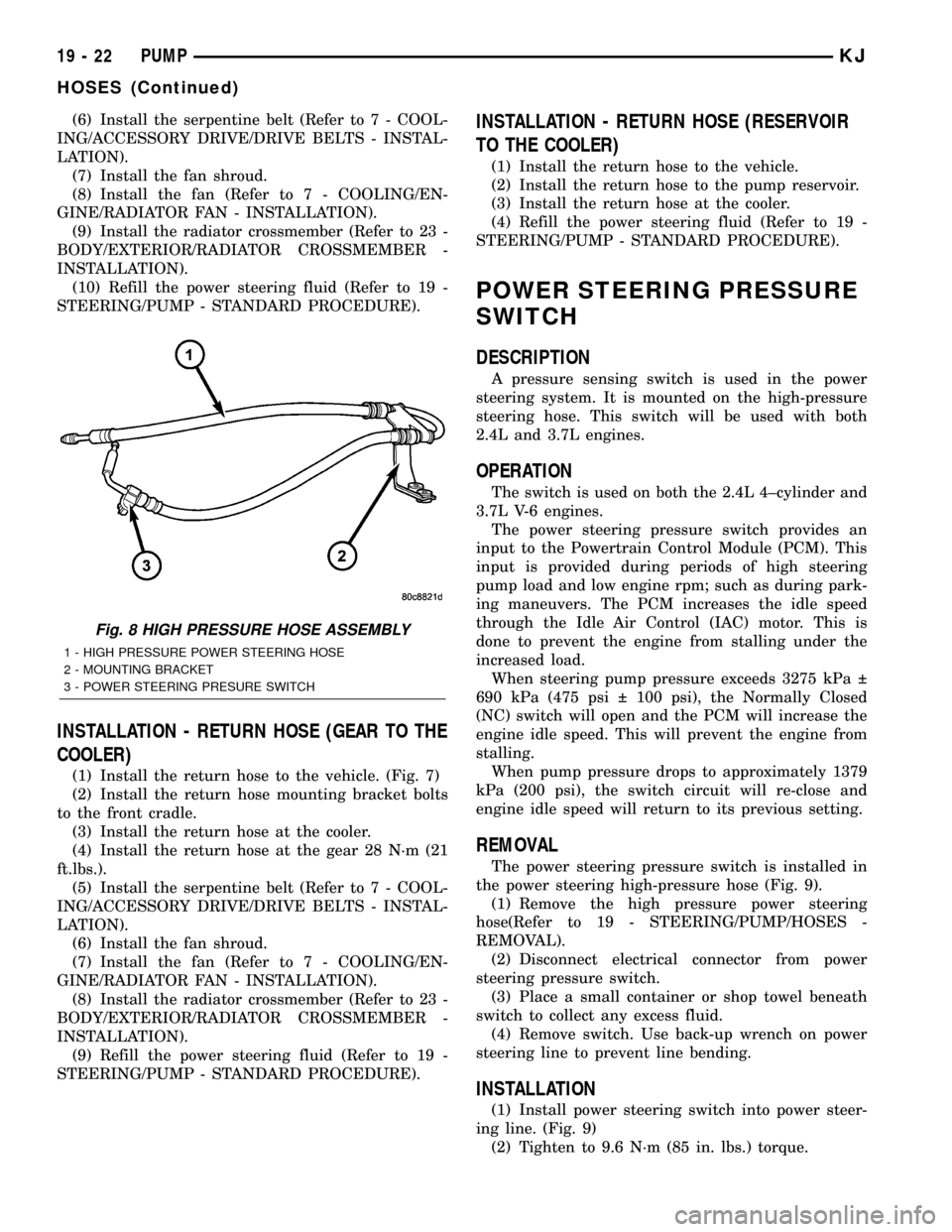
REMOVAL
The power steering pressure switch is installed in
the power steering high-pressure hose (Fig. 9).
(1) Remove the high pressure power steering
hose(Refer to 19 - STEERING/PUMP/HOSES -
REMOVAL).
(2) Disconnect electrical connector from power
steering pressure switch.
(3) Place a small container or shop towel beneath
switch to collect any excess fluid.
(4) Remove switch. Use back-up wrench on power
steering line to prevent line bending.
INSTALLATION
(1) Install power steering switch into power steer-
ing line. (Fig. 9)
(2) Tighten to 9.6 N´m (85 in. lbs.) torque.
Fig. 8 HIGH PRESSURE HOSE ASSEMBLY
1 - HIGH PRESSURE POWER STEERING HOSE
2 - MOUNTING BRACKET
3 - POWER STEERING PRESURE SWITCH
19 - 22 PUMPKJ
HOSES (Continued)
Page 1587 of 1803
DOOR
REMOVAL
(1) Disconnect the door wire harness electrical con-
nector at the A-pillar.
(2) Support the door with a suitable lifting device.
(3) Remove the bolts attaching the check strap to
the a-pillar.
NOTE: The epoxy washers should not be removed
from the hinge. If the washers are removed the door
may have to be re-adjusted.
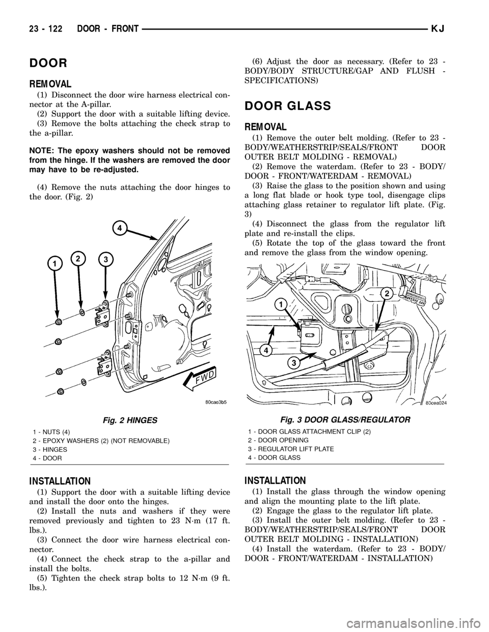
(4) Remove the nuts attaching the door hinges to
the door. (Fig. 2)
INSTALLATION
(1) Support the door with a suitable lifting device
and install the door onto the hinges.
(2) Install the nuts and washers if they were
removed previously and tighten to 23 N´m (17 ft.
lbs.).
(3) Connect the door wire harness electrical con-
nector.
(4) Connect the check strap to the a-pillar and
install the bolts.
(5) Tighten the check strap bolts to 12 N´m (9 ft.
lbs.).(6) Adjust the door as necessary. (Refer to 23 -
BODY/BODY STRUCTURE/GAP AND FLUSH -
SPECIFICATIONS)
DOOR GLASS
REMOVAL
(1) Remove the outer belt molding. (Refer to 23 -
BODY/WEATHERSTRIP/SEALS/FRONT DOOR
OUTER BELT MOLDING - REMOVAL)
(2) Remove the waterdam. (Refer to 23 - BODY/
DOOR - FRONT/WATERDAM - REMOVAL)
(3) Raise the glass to the position shown and using
a long flat blade or hook type tool, disengage clips
attaching glass retainer to regulator lift plate. (Fig.
3)
(4) Disconnect the glass from the regulator lift
plate and re-install the clips.
(5) Rotate the top of the glass toward the front
and remove the glass from the window opening.
INSTALLATION
(1) Install the glass through the window opening
and align the mounting plate to the lift plate.
(2) Engage the glass to the regulator lift plate.
(3) Install the outer belt molding. (Refer to 23 -
BODY/WEATHERSTRIP/SEALS/FRONT DOOR
OUTER BELT MOLDING - INSTALLATION)
(4) Install the waterdam. (Refer to 23 - BODY/
DOOR - FRONT/WATERDAM - INSTALLATION)
Fig. 2 HINGES
1 - NUTS (4)
2 - EPOXY WASHERS (2) (NOT REMOVABLE)
3 - HINGES
4 - DOOR
Fig. 3 DOOR GLASS/REGULATOR
1 - DOOR GLASS ATTACHMENT CLIP (2)
2 - DOOR OPENING
3 - REGULATOR LIFT PLATE
4 - DOOR GLASS
23 - 122 DOOR - FRONTKJ
Page 1588 of 1803
EXTERIOR HANDLE
REMOVAL
(1) Remove the door glass. (Refer to 23 - BODY/
DOOR - FRONT/DOOR GLASS - REMOVAL)
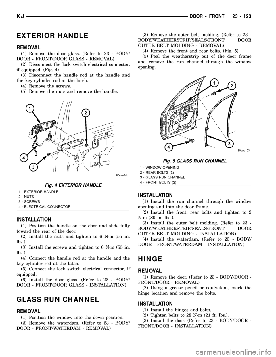
(2) Disconnect the lock switch electrical connector,
if equipped. (Fig. 4)
(3) Disconnect the handle rod at the handle and
the key cylinder rod at the latch.
(4) Remove the screws.
(5) Remove the nuts and remove the handle.
INSTALLATION
(1) Position the handle on the door and slide fully
toward the rear of the door.
(2) Install the nuts and tighten to 6 N´m (55 in.
lbs.).
(3) Install the screws and tighten to 6 N´m (55 in.
lbs.).
(4) Connect the handle rod at the handle and the
key cylinder rod at the latch.
(5) Connect the lock switch electrical connector, if
equipped.
(6) Install the door glass. (Refer to 23 - BODY/
DOOR - FRONT/DOOR GLASS - INSTALLATION)
GLASS RUN CHANNEL
REMOVAL
(1) Position the window into the down position.
(2) Remove the waterdam. (Refer to 23 - BODY/
DOOR - FRONT/WATERDAM - REMOVAL)(3) Remove the outer belt molding. (Refer to 23 -
BODY/WEATHERSTRIP/SEALS/FRONT DOOR
OUTER BELT MOLDING - REMOVAL)
(4) Remove the front and rear bolts. (Fig. 5)
(5) Peal the weatherstrip out of the door frame
and remove the run channel through the window
opening.
INSTALLATION
(1) Install the run channel through the window
opening and into the door frame.
(2) Install the front, rear bolts and tighten to 9
N´m (80 in. lbs.).
(3) Install the outer belt molding. (Refer to 23 -
BODY/WEATHERSTRIP/SEALS/FRONT DOOR
OUTER BELT MOLDING - INSTALLATION)
(4) Install the waterdam. (Refer to 23 - BODY/
DOOR - FRONT/WATERDAM - INSTALLATION)
HINGE
REMOVAL
(1) Remove the door. (Refer to 23 - BODY/DOOR -
FRONT/DOOR - REMOVAL)
(2) Using a grease pencil or equivalent, mark the
hinge location and remove the bolts.
INSTALLATION
(1) Install the hinges and bolts.
(2) Tighten bolts to 28 N´m (21 ft. lbs.).
(3) Install the door. (Refer to 23 - BODY/DOOR -
FRONT/DOOR - INSTALLATION)
Fig. 4 EXTERIOR HANDLE
1 - EXTERIOR HANDLE
2 - NUTS
3 - SCREWS
4 - ELECTRICAL CONNECTOR
Fig. 5 GLASS RUN CHANNEL
1 - WINDOW OPENING
2 - REAR BOLTS (2)
3 - GLASS RUN CHANNEL
4 - FRONT BOLTS (2)
KJDOOR - FRONT 23 - 123