2002 JEEP LIBERTY section 8
[x] Cancel search: section 8Page 1408 of 1803

(11) Remove module lockring (Fig. 40) using a
brass drift and hammer (counter-clockwise).
(12) Carefully lift upper section of pump module
from fuel tank a few inches(lift upper section
from tank very slowly until rubber gasket can
be retained. If not, gasket will fall into fuel
tank).
(13) Using an approved gas holding tank, drain
fuel tank through fuel pump module opening.
Tank Removal
(1) After draining tank, temporarily place upper
section of fuel pump module back into fuel tank.
(2) Raise vehicle.
(3) If equipped, remove fuel tank skid plate and
tow hooks. Certain equipment packages will also
require removal of the trailer hitch. Refer to Tow
Hooks, Trailer Hitch or Skid Plate in 23, Body for
removal/installation procedures.
(4) Disconnect fuel filter ground strap.
(5) Disconnect fuel filter outlet line from body
retention clip located on frame near front/center of
tank (Fig. 41). Place a small screwdriver into side of
clip and twist for removal. Also disconnect Leak
Detection Pump (LDP) line (Fig. 41) from this clip.(6) Remove both 3/4º hoses at sides of Leak Detec-
tion Pump (LDP) (Fig. 41).
(7) Disconnect 3/4º flow management valve hose
(Fig. 41) at EVAP canister.
(8) Remove fuel fill hose clamp (Fig. 42) at fuel
tank, and disconnect hose from fuel tank.
(9) A third fuel line is attached to bottom of fuel
filter. The disconnection point (quick-connect fitting)
for this 3rd line is approximately 1 foot from front of
tank towards front of vehicle (Fig. 41). Clean connec-
tion point before disconnection. Disconnect by press-
ing on tabs at side of quick-connect fitting. Also
disconnect LDP vent line near this same point.
(10) Disconnect 2 vacuum/vent hoses from plastic
retention clip at left/front of fuel tank line (Fig. 41).
(11) Support tank with a hydraulic jack.
(12) Remove 4 fuel tank strap bolts (Fig. 41) (2 at
front of tank; 2 at rear of tank), and remove both
tank support straps (Fig. 41).
(13) Carefully lower tank a few inches and discon-
nect electrical connector at top of LDP (Fig. 43). To
disconnect electrical connector: Push upward on red
colored tab to unlock. Push on black colored tab
while removing connector.
Fig. 40 TOP OF FUEL PUMP MODULE
1 - LOCK RING
2 - ALIGNMENT NOTCH
3 - FUEL FILTER FITTINGS (2)
4 - ORVR SYSTEM HOSE AND CLAMP
5 - FLOW MANAGEMENT VALVE
6 - ELECTRICAL CONNECTOR
7 - LEAK DETECTION PUMP
8 - FUEL TANK CHECK (CONTROL) VALVE
9 - FUEL PUMP MODULE (UPPER SECTION)Fig. 41 FRONT OF FUEL TANK
1 - TANK MOUNTING BOLTS (4)
2 - TANK MOUNTING STRAPS (2)
3 - LEAK DETECTION PUMP (LDP)
4 - BODY RETENTION CLIP (CENTER)
5 - LDP HOSES
6 - HOSE TO FUEL MANAGEMENT VALVE
7 - BODY RETENTION CLIP (LEFT/FRONT)
8 - QUICK-CONECT FITTING
9 - LDP LINE
14 - 26 FUEL DELIVERYKJ
FUEL TANK (Continued)
Page 1410 of 1803

(21) Install fuel pump module metal access plate
and 4 nuts. Tighten nuts to 3 N´m (26 in. lbs.)
torque.
(22) Position carpet and install 2 new cargo clamp
rivets into each cargo holdown clamp.
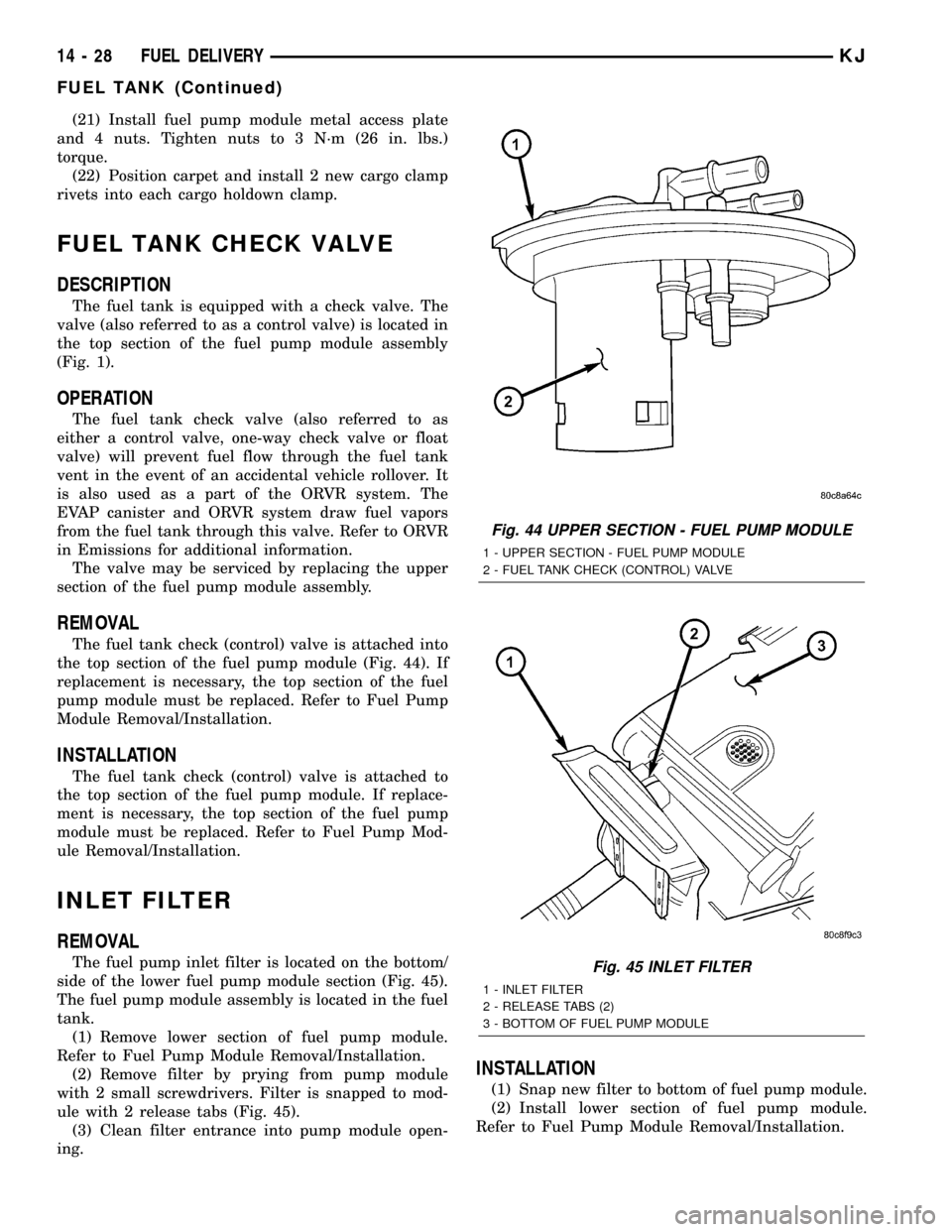
FUEL TANK CHECK VALVE
DESCRIPTION
The fuel tank is equipped with a check valve. The
valve (also referred to as a control valve) is located in
the top section of the fuel pump module assembly
(Fig. 1).
OPERATION
The fuel tank check valve (also referred to as
either a control valve, one-way check valve or float
valve) will prevent fuel flow through the fuel tank
vent in the event of an accidental vehicle rollover. It
is also used as a part of the ORVR system. The
EVAP canister and ORVR system draw fuel vapors
from the fuel tank through this valve. Refer to ORVR
in Emissions for additional information.
The valve may be serviced by replacing the upper
section of the fuel pump module assembly.
REMOVAL
The fuel tank check (control) valve is attached into
the top section of the fuel pump module (Fig. 44). If
replacement is necessary, the top section of the fuel
pump module must be replaced. Refer to Fuel Pump
Module Removal/Installation.
INSTALLATION
The fuel tank check (control) valve is attached to
the top section of the fuel pump module. If replace-
ment is necessary, the top section of the fuel pump
module must be replaced. Refer to Fuel Pump Mod-
ule Removal/Installation.
INLET FILTER
REMOVAL
The fuel pump inlet filter is located on the bottom/
side of the lower fuel pump module section (Fig. 45).
The fuel pump module assembly is located in the fuel
tank.
(1) Remove lower section of fuel pump module.
Refer to Fuel Pump Module Removal/Installation.
(2) Remove filter by prying from pump module
with 2 small screwdrivers. Filter is snapped to mod-
ule with 2 release tabs (Fig. 45).
(3) Clean filter entrance into pump module open-
ing.
INSTALLATION
(1) Snap new filter to bottom of fuel pump module.
(2) Install lower section of fuel pump module.
Refer to Fuel Pump Module Removal/Installation.
Fig. 44 UPPER SECTION - FUEL PUMP MODULE
1 - UPPER SECTION - FUEL PUMP MODULE
2 - FUEL TANK CHECK (CONTROL) VALVE
Fig. 45 INLET FILTER
1 - INLET FILTER
2 - RELEASE TABS (2)
3 - BOTTOM OF FUEL PUMP MODULE
14 - 28 FUEL DELIVERYKJ
FUEL TANK (Continued)
Page 1416 of 1803

REMOVAL
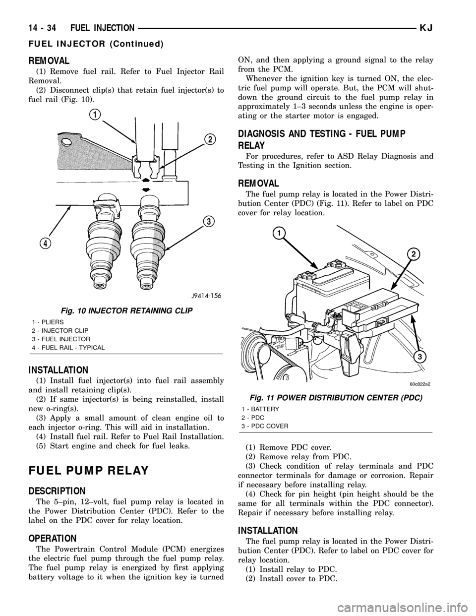
(1) Remove fuel rail. Refer to Fuel Injector Rail
Removal.
(2) Disconnect clip(s) that retain fuel injector(s) to
fuel rail (Fig. 10).
INSTALLATION
(1) Install fuel injector(s) into fuel rail assembly
and install retaining clip(s).
(2) If same injector(s) is being reinstalled, install
new o-ring(s).
(3) Apply a small amount of clean engine oil to
each injector o-ring. This will aid in installation.
(4) Install fuel rail. Refer to Fuel Rail Installation.
(5) Start engine and check for fuel leaks.
FUEL PUMP RELAY
DESCRIPTION
The 5±pin, 12±volt, fuel pump relay is located in
the Power Distribution Center (PDC). Refer to the
label on the PDC cover for relay location.
OPERATION
The Powertrain Control Module (PCM) energizes
the electric fuel pump through the fuel pump relay.
The fuel pump relay is energized by first applying
battery voltage to it when the ignition key is turnedON, and then applying a ground signal to the relay
from the PCM.
Whenever the ignition key is turned ON, the elec-
tric fuel pump will operate. But, the PCM will shut-
down the ground circuit to the fuel pump relay in
approximately 1±3 seconds unless the engine is oper-
ating or the starter motor is engaged.
DIAGNOSIS AND TESTING - FUEL PUMP
RELAY
For procedures, refer to ASD Relay Diagnosis and
Testing in the Ignition section.
REMOVAL
The fuel pump relay is located in the Power Distri-
bution Center (PDC) (Fig. 11). Refer to label on PDC
cover for relay location.
(1) Remove PDC cover.
(2) Remove relay from PDC.
(3) Check condition of relay terminals and PDC
connector terminals for damage or corrosion. Repair
if necessary before installing relay.
(4) Check for pin height (pin height should be the
same for all terminals within the PDC connector).
Repair if necessary before installing relay.
INSTALLATION
The fuel pump relay is located in the Power Distri-
bution Center (PDC). Refer to label on PDC cover for
relay location.
(1) Install relay to PDC.
(2) Install cover to PDC.
Fig. 10 INJECTOR RETAINING CLIP
1 - PLIERS
2 - INJECTOR CLIP
3 - FUEL INJECTOR
4 - FUEL RAIL - TYPICAL
Fig. 11 POWER DISTRIBUTION CENTER (PDC)
1 - BATTERY
2 - PDC
3 - PDC COVER
14 - 34 FUEL INJECTIONKJ
FUEL INJECTOR (Continued)
Page 1425 of 1803

WARNING: THE EXHAUST MANIFOLD, EXHAUST
PIPES AND CATALYTIC CONVERTER BECOME
VERY HOT DURING ENGINE OPERATION. ALLOW
ENGINE TO COOL BEFORE REMOVING OXYGEN
SENSOR.
(1) Raise and support vehicle.
(2) Disconnect wire connector from O2S sensor.
CAUTION: When disconnecting sensor electrical
connector, do not pull directly on wire going into
sensor.
(3) Remove O2S sensor with an oxygen sensor
removal and installation tool.
(4) Clean threads in exhaust pipe using appropri-
ate tap.
INSTALLATION
Threads of new oxygen sensors are factory coated
with anti-seize compound to aid in removal.DO
NOT add any additional anti-seize compound to
threads of a new oxygen sensor.
(1) Install O2S sensor. Tighten to 30 N´m (22 ft.
lbs.) torque.
(2) Connect O2S sensor wire connector.
(3) Lower vehicle.
THROTTLE BODY
DESCRIPTION
The throttle body is located on the intake manifold.
Fuel does not enter the intake manifold through the
throttle body. Fuel is sprayed into the manifold by
the fuel injectors.
OPERATION
Filtered air from the air cleaner enters the intake
manifold through the throttle body. The throttle body
contains an air control passage controlled by an Idle
Air Control (IAC) motor. The air control passage is
used to supply air for idle conditions. A throttle valve
(plate) is used to supply air for above idle conditions.
Certain sensors are attached to the throttle body.
The accelerator pedal cable, speed control cable and
transmission control cable (when equipped) are con-
nected to the throttle body linkage arm.
A (factory adjusted) set screw is used to mechani-
cally limit the position of the throttle body throttle
plate.Never attempt to adjust the engine idle
speed using this screw.All idle speed functions are
controlled by the PCM.
REMOVAL
2.4L
A (factory adjusted) set screw is used to mechani-
cally limit the position of the throttle body throttle
plate.Never attempt to adjust the engine idle
speed using this screw.All idle speed functions are
controlled by the Powertrain Control Module (PCM).
(1) Remove air cleaner tube at throttle body.
(2) Disconnect throttle body electrical connectors
at IAC motor and TPS.
(3) Remove all control cables from throttle body
(lever) arm. Refer to the Accelerator Pedal and Throt-
tle Cable section for removal/installation procedures.
(4) Disconnect necessary vacuum lines at throttle
body.
(5) Remove 3 throttle body mounting bolts (Fig.
23).
(6) Remove throttle body from intake manifold.
(7) Check condition of old throttle body-to-intake
manifold o-ring.
3.7L
A (factory adjusted) set screw is used to mechani-
cally limit the position of the throttle body throttle
plate.Never attempt to adjust the engine idle
speed using this screw.All idle speed functions are
controlled by the Powertrain Control Module (PCM).
(1) Remove air cleaner tube at throttle body.
(2) Disconnect throttle body electrical connectors
at IAC motor and TPS.
Fig. 23 THROTTLE BODY MOUNTING BOLTS - 2.4L
1 - THROTTLE BODY
2 - IGNITION COIL
3 - MOUNTING BOLTS (3)
KJFUEL INJECTION 14 - 43
OXYGEN SENSOR (Continued)
Page 1426 of 1803

(3) Remove all control cables from throttle body
(lever) arm. Refer to the Accelerator Pedal and Throt-
tle Cable section for removal/installation procedures.
(4) Disconnect necessary vacuum lines at throttle
body.
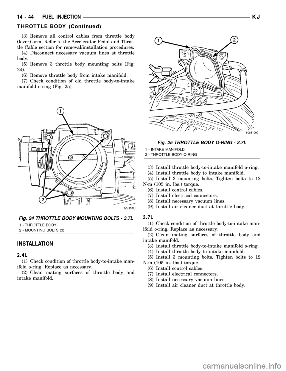
(5) Remove 3 throttle body mounting bolts (Fig.
24).
(6) Remove throttle body from intake manifold.
(7) Check condition of old throttle body-to-intake
manifold o-ring (Fig. 25).
INSTALLATION
2.4L
(1) Check condition of throttle body-to-intake man-
ifold o-ring. Replace as necessary.
(2) Clean mating surfaces of throttle body and
intake manifold.(3) Install throttle body-to-intake manifold o-ring.
(4) Install throttle body to intake manifold.
(5) Install 3 mounting bolts. Tighten bolts to 12
N´m (105 in. lbs.) torque.
(6) Install control cables.
(7) Install electrical connectors.
(8) Install necessary vacuum lines.
(9) Install air cleaner duct at throttle body.
3.7L
(1) Check condition of throttle body-to-intake man-
ifold o-ring. Replace as necessary.
(2) Clean mating surfaces of throttle body and
intake manifold.
(3) Install throttle body-to-intake manifold o-ring.
(4) Install throttle body to intake manifold.
(5) Install 3 mounting bolts. Tighten bolts to 12
N´m (105 in. lbs.) torque.
(6) Install control cables.
(7) Install electrical connectors.
(8) Install necessary vacuum lines.
(9) Install air cleaner duct at throttle body.
Fig. 24 THROTTLE BODY MOUNTING BOLTS - 3.7L
1 - THROTTLE BODY
2 - MOUNTING BOLTS (3)
Fig. 25 THROTTLE BODY O-RING - 3.7L
1 - INTAKE MANIFOLD
2 - THROTTLE BODY O-RING
14 - 44 FUEL INJECTIONKJ
THROTTLE BODY (Continued)
Page 1438 of 1803

SPECIFICATIONS
TORQUE CHART
TORQUE SPECIFICATIONS
DESCRIPTION N´m Ft. Lbs. In. Lbs.
Tilt Steering Column
Steering Wheel Bolt54 40 Ð
Tilt Steering Column
Mounting Bolts17 Ð 150
Tilt Steering Column
Coupler Bolt49 36 Ð
Non-Tilt Steering Column
Steering Wheel Bolt54 40 Ð
Non-Tilt Steering Column
Mounting Bolts17 Ð 150
Non-Tilt Steering Column
Coupler Bolt49 36 Ð
Ignition Switch Screws 2 Ð 17
SPECIAL TOOLS
STEERING COLUMN
IGNITION SWITCH
DESCRIPTION
The electrical ignition switch is located on the
steering column. It is used as the main on/off switch-
ing device for most electrical components. The
mechanical key lock cylinder is used to engage/disen-
gage the electrical ignition switch.
DIAGNOSIS AND TESTING - IGNITION SWITCH
ELECTRICAL DIAGNOSIS
For ignition switch electrical schematics, Refer to
the appropriate section for the component.
MECHANICAL DIAGNOSIS (KEY DIFFICULT TO
ROTATE)
Vehicles equipped with an automatic trans-
mission and a floor mounted shifter:a cable is
used to connect the interlock device in the steering
column assembly, to the transmission floor shift
lever. This interlock system is used to lock the trans-
mission shifter in the PARK position when the key
lock cylinder is rotated to the LOCKED or ACCES-
SORY position. If the ignition key is difficult to
rotate to or from the LOCK or ACCESSORY position,
it may not be the fault of the key cylinder or the
steering column components. The brake transmission
shift interlock cable may be out of adjustment. (Refer
to 21 - TRANSMISSION/TRANSAXLE/AUTOMATIC
- 30RH/GEAR SHIFT CABLE - ADJUSTMENTS).
The interlock system within the steering column is
not serviceable. If repair is necessary, the steering
column assembly must be replaced. (Refer to 19 -
STEERING/COLUMN - REMOVAL).
Vehicles equipped with a manual transmis-
sion and a floor mounted shifter:on certain mod-
els, a button is located on the steering column behind
the ignition key lock cylinder. The button must be
manually depressed to allow rotation of the ignition
key lock cylinder to the LOCK or ACCESSORY posi-
tion. If it is difficult to rotate the key to the LOCK or
ACCESSORY position, the lever mechanism may be
defective. This mechanism is not serviceable. If
repair is necessary, the steering column assembly
must be replaced.(Refer to 19 - STEERING/COL-
UMN - REMOVAL).
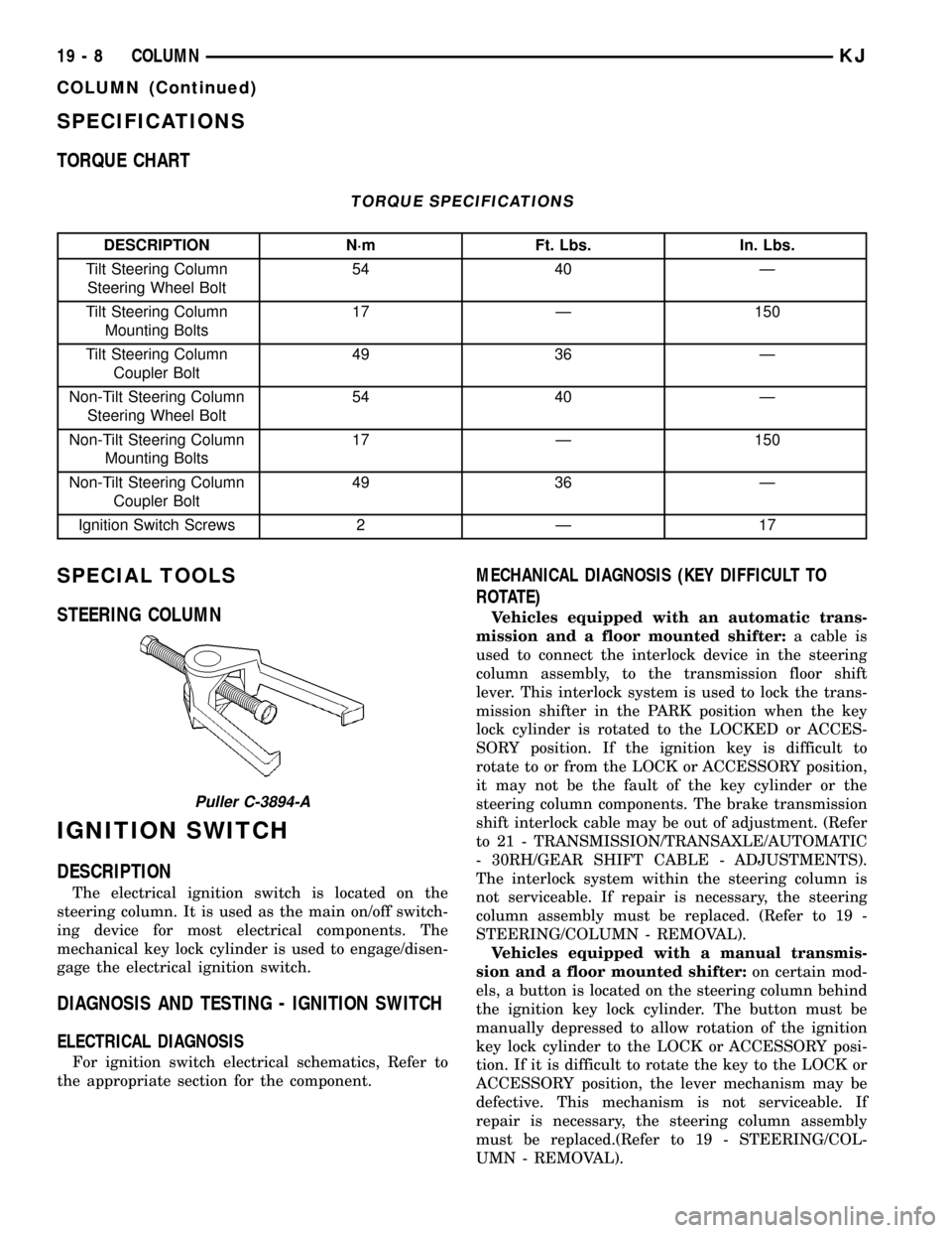
Puller C-3894-A
19 - 8 COLUMNKJ
COLUMN (Continued)
Page 1440 of 1803

KEY-IN IGNITION SWITCH
DESCRIPTION
The key-in ignition switch is integral to the igni-
tion switch, which is mounted on the left side of the
steering column, opposite the ignition lock cylinder.
It closes a path to ground for the instrument cluster
chime warning circuitry when the ignition key is
inserted in the ignition lock cylinder and the driver
door jamb switch is closed (driver door is open). The
key-in ignition switch opens the ground path when
the key is removed from the ignition lock cylinder.
The key-in ignition switch cannot be repaired and,
if faulty or damaged, the entire ignition switch must
be replaced. (Refer to 19 - STEERING/COLUMN/IG-
NITION SWITCH - REMOVAL).
DIAGNOSIS AND TESTING - KEY-IN IGNITION
SWITCH
For circuit descriptions and diagrams, Refer to the
appropriate sections on the individual components.
WARNING: ON VEHICLES EQUIPPED WITH AIR-
BAGS, REFER TO ELECTRICAL - PASSIVE
RESTRAINT SYSTEMS BEFORE ATTEMPTING ANY
STEERING WHEEL, STEERING COLUMN, OR
INSTRUMENT PANEL COMPONENT DIAGNOSIS OR
SERVICE. FAILURE TO TAKE THE PROPER PRE-
CAUTIONS COULD RESULT IN ACCIDENTAL AIR-
BAG DEPLOYMENT AND POSSIBLE PERSONAL
INJURY.
(1) Disconnect and isolate the battery negative
cable. Remove the steering column shrouds. Unplug
the key-in ignition switch wire harness connector
from the ignition switch.
(2) Check for continuity between the key-in switch
sense circuit and the left front door jamb switch
sense circuit terminals of the key-in ignition switch.
There should be continuity with the key in the igni-
tion lock cylinder, and no continuity with the key
removed from the ignition lock cylinder. If OK, go to
Step 3. If not OK, replace the faulty ignition switch
assembly.
(3) Check for continuity between the left front door
jamb switch sense circuit cavity of the key-in ignition
switch wire harness connector and a good ground.
There should be continuity with the driver door open,
and no continuity with the driver door closed. If OK,
see the diagnosis for Instrument Cluster in this
group. If not OK, repair the circuit to the driver door
jamb switch as required.
LOCK CYLINDER
REMOVAL
The ignition key must be in the key cylinder for
cylinder removal. The key cylinder must be removed
first before removing ignition switch.
(1) If equipped with an automatic transmission,
place shifter in PARK position.
(2) Remove the lower shroud cover.
(3) Remove the remote keyless entry (R.K.E.) mod-
ule.
(4) Remove the halo ring around the lock cylinder.
(5) Rotate key to ON position.
(6) A release tang is located on bottom of key cyl-
inder (Fig. 10).
(7) Position a small screwdriver or pin punch into
tang access hole on bottom of steering column (Fig.
11).
(8) Push the pin punch up while pulling key cylin-
der from steering column.
Fig. 10 LOCK CYLINDER RELEASE TANG
1 - Lock Cylinder
2 - Release Tang
19 - 10 COLUMNKJ
Page 1464 of 1803

Initial inflation of the tire forces the bead over
these raised sections. In case of rapid loss of air pres-
sure, the raised sections help hold the tire on the
wheel.
The wheel studs and nuts are designed for specific
applications. All aluminum and some steel wheels
have wheel stud nuts with an enlarged nose. This
enlarged nose is necessary to ensure proper retention
of the wheels. Do not use replacement studs or nuts
with a different design or lesser quality.
DIAGNOSIS AND TESTING - WHEELS
Inspect wheels for:
²Excessive run out
²Dents or cracks
²Damaged wheel lug nut holes
²Air Leaks from any area or surface of the rim
NOTE: Do not attempt to repair a wheel by hammer-
ing, heating or welding.
If a wheel is damaged an original equipment
replacement wheel should be used. When obtaining
replacement wheels, they should be equivalent in
load carrying capacity. The diameter, width, offset,
pilot hole and bolt circle of the wheel should be the
same as the original wheel.
WARNING: FAILURE TO USE EQUIVALENT
REPLACEMENT WHEELS MAY ADVERSELY
AFFECT THE SAFETY AND HANDLING OF THE
VEHICLE. USED WHEELS ARE NOT RECOM-
MENDED. THE SERVICE HISTORY OF THE WHEEL
MAY HAVE INCLUDED SEVERE TREATMENT OR
VERY HIGH MILEAGE. THE RIM COULD FAIL WITH-
OUT WARNING.
STANDARD PROCEDURE
STANDARD PROCEDURE - WHEEL
REPLACEMENT
Wheels must be replaced if they have:
²Excessive runout
²Bent or dented
²Leak air through welds
²Have damaged bolt holes
Wheel repairs employing hammering, heating, or
welding are not allowed.
Original equipment wheels are available through
your dealer. Replacement wheels from any other
source should be equivalent in:
²Load carrying capacity
²Diameter
²Width
²Offset²Mounting configuration
Failure to use equivalent replacement wheels may
affect the safety and handling of your vehicle.
Replacement withusedwheels is not recommended.
Their service history may have included severe treat-
ment.
STANDARD PROCEDURE - WHEEL MOUNTING
The wheel studs and nuts are designed for specific
applications. They must be replaced with equivalent
parts. Do not use replacement parts of lesser quality
or a substitute design. All aluminum and some steel
wheels have wheel stud nuts which feature an
enlarged nose. This enlarged nose is necessary to
ensure proper retention of the aluminum wheels.
NOTE: Do not use chrome plated lug nuts with
chrome plated wheels.
Before installing the wheel, be sure to remove any
build up of corrosion on the wheel mounting surfaces.
Ensure wheels are installed with good metal-to-metal
contact. Improper installation could cause loosening
of wheel nuts. This could affect the safety and han-
dling of your vehicle.
To install the wheel, first position it properly on
the mounting surface. All wheel nuts should then be
tightened just snug. Gradually tighten them in
sequence to the proper torque specification (Fig. 18).
Never use oil or grease on studs or nuts.
Fig. 18 Lug Nut Tightening Pattern
22 - 10 TIRES/WHEELSKJ
WHEELS (Continued)