2002 JEEP LIBERTY section 8
[x] Cancel search: section 8Page 1292 of 1803
IDLER SHAFT
REMOVAL
(1) Remove the primary and secondary timing
chains and sprockets. Refer to procedure in this sec-
tion.
NOTE: To remove the idler shaft, it is necessary to
tap threads into the shaft, to install the removal
tool.
(2) Using a 12 mm X 1.75 tap, cut threads in the
idler shaft center bore.
(3) Cover the radiator core with a suitable cover.
CAUTION: Use care when removing the idler shaft,
Do not strike the radiator cooling fins with the slide
hammer.
(4) Using Special Tool 8517 Slide Hammer, remove
the idler shaft.
INSTALLATION
(1) Thoroughly clean the idler shaft bore.
(2) Position the idler shaft in the bore.
NOTE: The two lubrication holes in the idler shaft
do not require any special alignment.
NOTE: Before using the retaining bolt to install the
idler shaft, coat the threads and the pilot on the
idler shaft, with clean engine oil.
(3) Using the primary idler sprocket retaining bolt
and washer, carefully draw the idler shaft into the
bore until fully seated.
(4) Coat the idler shaft with clean engine oil.
(5) Install the timing chains and sprockets. Refer
to procedure in this section.
TIMING BELT/CHAIN AND
SPROCKET(S
REMOVAL
(1) Disconnect negative cable from battery.
(2) Drain cooling system. Refer to COOLING SYS-
TEM for procedures.
(3) Remove right and left cylinder head covers.
Refer to CYLINDER HEAD COVER.
(4) Remove radiator fan shroud. Refer to COOL-
ING SYSTEM for procedure.
(5) Rotate engine until timing mark on crankshaft
damper aligns with TDC mark on timing chain cover
(Fig. 103) (#1 cylinder exhaust stroke) and the cam-
shaft sprocket ªV6º marks are at the 12 o'clock posi-
tion (Fig. 102).
CAUTION: The nut on the right side camshaft
sprocket should not be removed for any reason, as
the sprocket and camshaft sensor target wheel is
serviced as an assembly. If the nut was removed
retorque nut to 5 N´m (44 in. lbs.).
(6) Remove power steering pump. Refer to STEER-
ING for procedure.
(7) Remove access plug from left and right cylinder
heads for access to chain guide fasteners (Fig. 104).
(8) Remove the oil fill housing to gain access to the
right side tensioner arm fastener.
(9) Remove crankshaft damper and timing chain
cover. Refer to procedures.
(10) Collapse and pin primary chain tensioner.
CAUTION: Plate behind left secondary chain ten-
sioner could fall into oil pan. Therefore, cover pan
opening.
(11) Remove secondary chain tensioners.
(12) Remove camshaft position and crankshaft
position sensors (Fig. 105) and (Fig. 106).
KJENGINE - 3.7L 9 - 77
Page 1301 of 1803
(7) Crank engine until maximum pressure is
reached on gage. Record this pressure as #1 cylinder
pressure.
(8) Repeat the previous step for all remaining cyl-
inders.
(9) Compression should not be less than 689 kPa
(100 psi) and not vary more than 25 percent from cyl-
inder to cylinder.
(10) If one or more cylinders have abnormally low
compression pressures, repeat the compression test.
(11) If the same cylinder or cylinders repeat an
abnormally low reading on the second compression
test, it could indicate the existence of a problem in
the cylinder in question.The recommended com-
pression pressures are to be used only as a
guide to diagnosing engine problems. An engine
should not be disassembled to determine the
cause of low compression unless some malfunc-
tion is present.
DIAGNOSIS AND TESTING - ENGINE OIL LEAK
INSPECTION
Begin with a thorough visual inspection of the
engine, particularly at the area of the suspected leak.
If an oil leak source is not readily identifiable, the
following steps should be followed:
(1) Do not clean or degrease the engine at this
time because some solvents may cause rubber to
swell, temporarily stopping the leak.
(2) Add an oil soluble dye (use as recommended by
manufacturer). Start the engine and let idle for
approximately 15 minutes. Check the oil dipstick to
make sure the dye is thoroughly mixed as indicated
with a bright yellow color under a black light.
(3) Using a black light, inspect the entire engine
for fluorescent dye, particularly at the suspected area
of oil leak. If the oil leak is found and identified,
repair as necessary.
(4) If dye is not observed, drive the vehicle at var-
ious speeds for approximately 24 km (15 miles), and
repeat inspection.
(5)If the oil leak source is not positively
identified at this time, proceed with the air leak
detection test method as follows:
²Disconnect the fresh air hose (make-up air) at
the cylinder head cover and plug or cap the nipple on
the cover.
²Remove the PCV valve hose from the cylinder
head cover. Cap or plug the PCV valve nipple on the
cover.
²Attach an air hose with pressure gauge and reg-
ulator to the dipstick tube.
CAUTION: Do not subject the engine assembly to
more than 20.6 kpa (3 PSI) of test pressure.²Gradually apply air pressure from 1 psi to 2.5
psi maximum while applying soapy water at the sus-
pected source. Adjust the regulator to the suitable
test pressure that provides the best bubbles which
will pinpoint the leak source. If the oil leak is
detected and identified, repair per service manual
procedures.
²If the leakage occurs at the crankshaft rear oil
seal area, refer to the section, Inspection for Rear
Seal Area Leak.
(6) If no leaks are detected, turn off the air supply.
Remove the air hose, all plugs, and caps. Install the
PCV valve and fresh air hose (make-up air). Proceed
to next step.
(7) Clean the oil off the suspect oil leak area using
a suitable solvent. Drive the vehicle at various
speeds approximately 24 km (15 miles). Inspect the
engine for signs of an oil leak by using a black light.
NOTE: If oil leakage is observed at the dipstick tube
to block location; remove the tube, clean and reseal
using MoparTStud & Bearing Mount (press fit tube
applications only), and for O-ring style tubes,
remove tube and replace the O-ring seal.
INSPECTION FOR REAR SEAL AREA LEAKS
Since it is sometimes difficult to determine the
source of an oil leak in the rear seal area of the
engine, a more involved inspection is necessary. The
following steps should be followed to help pinpoint
the source of the leak.
If the leakage occurs at the crankshaft rear oil seal
area:
(1) Disconnect the battery.
(2) Raise the vehicle.
(3) Remove torque converter or clutch housing
cover and inspect rear of block for evidence of oil.
Use a black light to check for the oil leak. If a leak is
present in this area, remove transmission for further
inspection.
(a) Circular spray pattern generally indicates
seal leakage or crankshaft damage.
(b) Where leakage tends to run straight down,
possible causes are a porous block, oil gallery cup
plug, bedplate to cylinder block mating surfaces
and seal bore. See proper repair procedures for
these items.
(4) If no leaks are detected, pressurize the crank-
case as previously described.
CAUTION: Do not exceed 20.6 kPa (3 psi).
(5) If the leak is not detected, very slowly turn the
crankshaft and watch for leakage. If a leak is
detected between the crankshaft and seal while
slowly turning the crankshaft, it is possible the
9s - 4 ENGINEKJ
ENGINE - 2.4L (Continued)
Page 1337 of 1803
(4) Install flex plate. Apply MopartLock & Seal
Adhesive to bolt threads and tighten bolts to 95 N´m
(70 ft. lbs.).
(5) Install the transmission.
PISTON & CONNECTING ROD
DESCRIPTION
The pistons are made of a cast aluminum alloy.
The pistons have pressed-in pins attached to forged
powdered metal connecting rods. The pistons pin is
offset 1 mm (0.0394 in.) towards the thrust side of
the piston. The connecting rods are a cracked cap
design and are not repairable. Hex head cap screws
are used to provide alignment and durability in the
assembly. The pistons and connecting rods are ser-
viced as an assembly.
OPERATION
The piston and connecting rod is the link between
the combustion force to the crankshaft.
REMOVAL
NOTE: Cylinder Head must be removed before Pis-
tons and Rods. Refer to Cylinder Head Removal in
this section.
(1) Remove top ridge of cylinder bores with a reli-
able ridge reamer before removing pistons from cyl-
inder block.Be sure to keep tops of pistons
covered during this operation. Mark piston with
matching cylinder number (Fig. 60).
(2) Remove oil pan. Scribe the cylinder number on
the side of the rod and cap (Fig. 61) for identification.
(3) Pistons have a directional stamping in the
front half of the piston facing towards thefrontof
engine.
(4) Pistons and connecting rods must be removed
from top of cylinder block. Rotate crankshaft so that
each connecting rod is centered in cylinder bore.
(5) Remove Balance Shaft Assembly. Refer to Bal-
ance Shaft Removal in this section.
(6) Remove connecting rod cap bolts. Push each
piston and rod assembly out of cylinder bore.
NOTE: Be careful not to nick crankshaft journals.
(7) After removal, install bearing cap on the mat-
ing rod.
(8) Piston and Rods are serviced as an assembly.
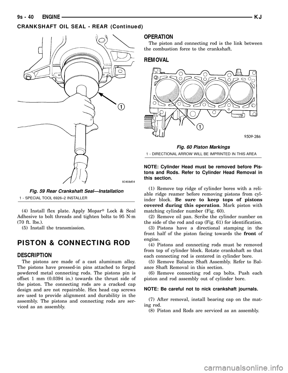
Fig. 59 Rear Crankshaft SealÐInstallation
1 - SPECIAL TOOL 6926±2 INSTALLER
Fig. 60 Piston Markings
1 - DIRECTIONAL ARROW WILL BE IMPRINTED IN THIS AREA
9s - 40 ENGINEKJ
CRANKSHAFT OIL SEAL - REAR (Continued)
Page 1358 of 1803
INSTALLATION
BALANCE SHAFT TIMING
BALANCE SHAFT INSTALLATION
Balance shaft and carrier assembly installation is
the reverse of the removal procedure.During instal-
lation crankshaft-to-balance shaft timing must
be established. Refer to Timing procedure in
this section.
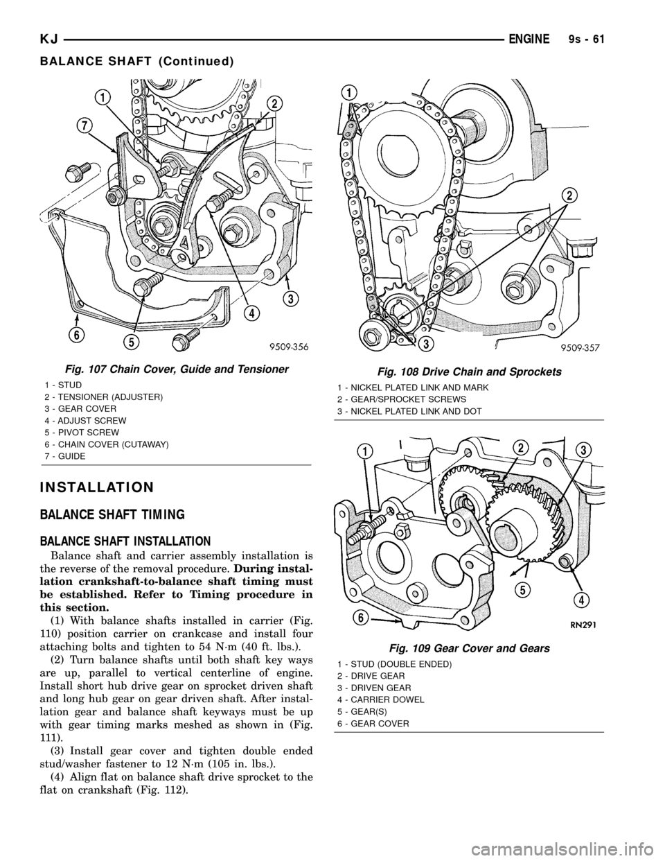
(1) With balance shafts installed in carrier (Fig.
110) position carrier on crankcase and install four
attaching bolts and tighten to 54 N´m (40 ft. lbs.).
(2) Turn balance shafts until both shaft key ways
are up, parallel to vertical centerline of engine.
Install short hub drive gear on sprocket driven shaft
and long hub gear on gear driven shaft. After instal-
lation gear and balance shaft keyways must be up
with gear timing marks meshed as shown in (Fig.
111).
(3) Install gear cover and tighten double ended
stud/washer fastener to 12 N´m (105 in. lbs.).
(4) Align flat on balance shaft drive sprocket to the
flat on crankshaft (Fig. 112).
Fig. 107 Chain Cover, Guide and Tensioner
1 - STUD
2 - TENSIONER (ADJUSTER)
3 - GEAR COVER
4 - ADJUST SCREW
5 - PIVOT SCREW
6 - CHAIN COVER (CUTAWAY)
7 - GUIDE
Fig. 108 Drive Chain and Sprockets
1 - NICKEL PLATED LINK AND MARK
2 - GEAR/SPROCKET SCREWS
3 - NICKEL PLATED LINK AND DOT
Fig. 109 Gear Cover and Gears
1 - STUD (DOUBLE ENDED)
2 - DRIVE GEAR
3 - DRIVEN GEAR
4 - CARRIER DOWEL
5 - GEAR(S)
6 - GEAR COVER
KJENGINE9s-61
BALANCE SHAFT (Continued)
Page 1384 of 1803
FUEL DELIVERY
DESCRIPTION
The fuel delivery system consists of:
²the 2±section fuel pump module containing the
electric fuel pump, fuel pressure regulator, fuel gauge
sending unit (fuel level sensor) and a fuel filter
located inside the lower section of pump module
²fuel tubes/lines/hoses
²A separately mounted main fuel filter²quick-connect fittings
²fuel injector rail
²fuel tank
²fuel tank filler/vent tube assembly
²fuel tank filler tube cap
²accelerator pedal
²throttle cable
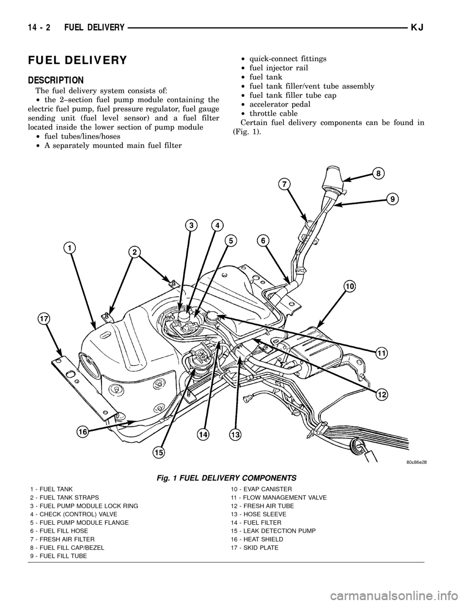
Certain fuel delivery components can be found in
(Fig. 1).
Fig. 1 FUEL DELIVERY COMPONENTS
1 - FUEL TANK 10 - EVAP CANISTER
2 - FUEL TANK STRAPS 11 - FLOW MANAGEMENT VALVE
3 - FUEL PUMP MODULE LOCK RING 12 - FRESH AIR TUBE
4 - CHECK (CONTROL) VALVE 13 - HOSE SLEEVE
5 - FUEL PUMP MODULE FLANGE 14 - FUEL FILTER
6 - FUEL FILL HOSE 15 - LEAK DETECTION PUMP
7 - FRESH AIR FILTER 16 - HEAT SHIELD
8 - FUEL FILL CAP/BEZEL 17 - SKID PLATE
9 - FUEL FILL TUBE
14 - 2 FUEL DELIVERYKJ
Page 1385 of 1803
OPERATION
Fuel is picked up in the fuel tank by the fuel pump
module. This module is located on the bottom of the
fuel tank.
A fuel return system is provided within the fuel
pump module using check valves. A separate fuel
return line from the engine to the tank is not used.
The fuel pressure regulator and the main fuel filter
are not combined. They are separate items.
The fuel tank assembly consists of: the fuel tank,
fuel pump module assembly, fuel pump module lock
ring/gasket, ORVR components. Refer to 25, Emis-
sion Control System for ORVR information.
A fuel filler/vent tube assembly using a pressure/
vacuum, 1/4 turn fuel filler cap is used. The fuel
filler tube contains a flap door located below the fuel
fill cap. A one-way check valve is installed into the
tanks fuel fill fitting.
Also to be considered part of the fuel system is the
evaporation control system and ORVR system. This
is designed to reduce the emission of fuel vapors into
the atmosphere. The description and function of the
Evaporative Control System is found in 25, Emission
Control Systems.
Both fuel filters (mounted to front of fuel tank, and
inside the bottom fuel pump module) are designed for
extended service. They do not require normal sched-
uled maintenance. The bottom section of the fuel
pump module (with included filter) should only be
replaced if a diagnostic procedure indicates to do so.
Also, the fuel filter mounted to the front of the fuel
tank should only be replaced if a diagnostic proce-
dure indicates to do so.
DIAGNOSIS AND TESTING - FUEL PRESSURE
LEAK DOWN TEST
Use this test in conjunction with the Fuel Pump
Pressure Test and Fuel Pump Capacity Test.
Check Valve Operation:The electric fuel pump
outlet contains a one-way check valve to prevent fuel
flow back into the tank and to maintain fuel supply
line pressure (engine warm) when pump is not oper-
ational. It is also used to keep the fuel supply line
full of gasoline when pump is not operational. After
the vehicle has cooled down, fuel pressure may drop
to 0 psi (cold fluid contracts), but liquid gasoline will
remain in fuel supply line between the check valve
and fuel injectors.Fuel pressure that has
dropped to 0 psi on a cooled down vehicle
(engine off) is a normal condition.When the elec-
tric fuel pump is activated, fuel pressure should
immediately(1±2 seconds) rise to specification.
Abnormally long periods of cranking to restart a
hotengine that has been shut down for a short
period of time may be caused by:
²Fuel pressure bleeding past a fuel injector(s).²Fuel pressure bleeding past the check valve in
the fuel pump module.
(1) Disconnect the fuel inlet line at fuel rail. Refer
to Quick Connect Fittings for procedures. On some
engines, air cleaner housing removal may be neces-
sary before fuel line disconnection.
(2) Obtain correct Fuel Line Pressure Test Adapter
Tool Hose. Tool number 6539 is used for 5/16º fuel
lines and tool number 6631 is used for 3/8º fuel lines.
(3) Connect correct Fuel Line Pressure Test
Adapter Tool Hose between disconnected fuel line
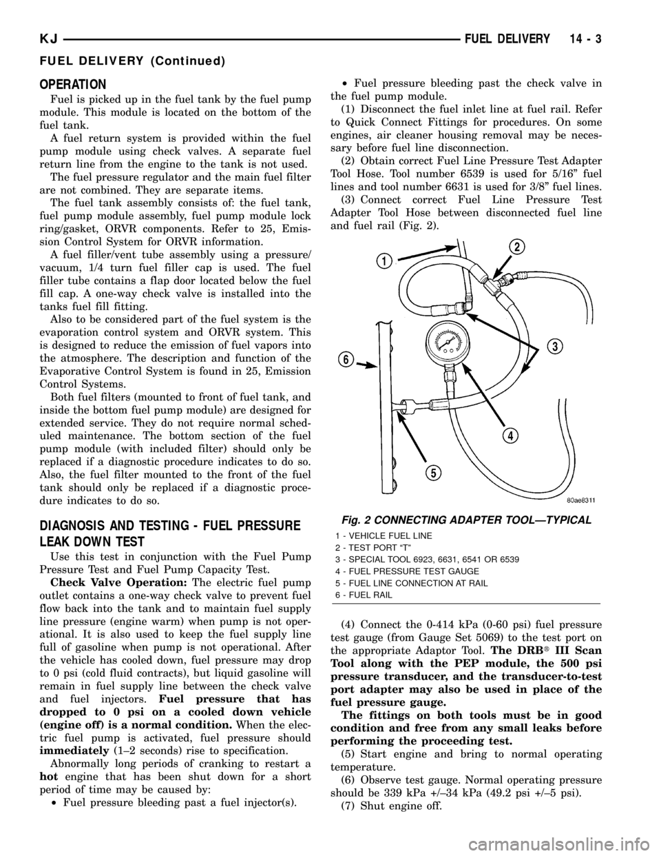
and fuel rail (Fig. 2).
(4) Connect the 0-414 kPa (0-60 psi) fuel pressure
test gauge (from Gauge Set 5069) to the test port on
the appropriate Adaptor Tool.The DRBtIII Scan
Tool along with the PEP module, the 500 psi
pressure transducer, and the transducer-to-test
port adapter may also be used in place of the
fuel pressure gauge.
The fittings on both tools must be in good
condition and free from any small leaks before
performing the proceeding test.
(5) Start engine and bring to normal operating
temperature.
(6) Observe test gauge. Normal operating pressure
should be 339 kPa +/±34 kPa (49.2 psi +/±5 psi).
(7) Shut engine off.
Fig. 2 CONNECTING ADAPTER TOOLÐTYPICAL
1 - VEHICLE FUEL LINE
2 - TEST PORT ªTº
3 - SPECIAL TOOL 6923, 6631, 6541 OR 6539
4 - FUEL PRESSURE TEST GAUGE
5 - FUEL LINE CONNECTION AT RAIL
6 - FUEL RAIL
KJFUEL DELIVERY 14 - 3
FUEL DELIVERY (Continued)
Page 1389 of 1803
(3) Remove 4 fuel pump module access plate nuts
(Fig. 3).
(4) While applying heat from a heat gun, carefully
pry up fuel pump module access plate. Take care not
to bend plate.
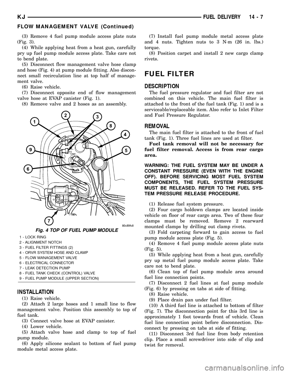
(5) Disconnect flow management valve hose clamp
and hose (Fig. 4) at pump module fitting. Also discon-
nect small recirculation line at top half of manage-
ment valve.
(6) Raise vehicle.
(7) Disconnect opposite end of flow management
valve hose at EVAP canister (Fig. 1).
(8) Remove valve and 2 hoses as an assembly.
INSTALLATION
(1) Raise vehicle.
(2) Attach 2 large hoses and 1 small line to flow
management valve. Position this assembly to top of
fuel tank.
(3) Connect valve hose at EVAP canister.
(4) Lower vehicle.
(5) Attach valve hose and clamp to top of fuel
pump module.
(6) Apply silicone sealant to bottom of fuel pump
module metal access plate.(7) Install fuel pump module metal access plate
and 4 nuts. Tighten nuts to 3 N´m (26 in. lbs.)
torque.
(8) Position carpet and install 2 new cargo clamp
rivets.
FUEL FILTER
DESCRIPTION
The fuel pressure regulator and fuel filter are not
combined on this vehicle. The main fuel filter is
attached to the front of the fuel tank (Fig. 1) and is a
serviceable/replaceable item. Also refer to Inlet Filter
and Fuel Pressure Regulator.
REMOVAL
The main fuel filter is attached to the front of fuel
tank (Fig. 1). Three fuel lines are used at filter.
Fuel tank removal will not be necessary for
fuel filter removal. Access is from rear cargo
area.
WARNING: THE FUEL SYSTEM MAY BE UNDER A
CONSTANT PRESSURE (EVEN WITH THE ENGINE
OFF). BEFORE SERVICING MOST FUEL SYSTEM
COMPONENTS, THE FUEL SYSTEM PRESSURE
MUST BE RELEASED. REFER TO THE FUEL SYS-
TEM PRESSURE RELEASE PROCEDURE.
(1) Release fuel system pressure.
(2) Four cargo holdown clamps are located inside
vehicle on floor of rear cargo area. Two of these four
clamps must be removed. Remove 2 rearward
mounted clamps by drilling out clamp rivets.
(3) Fold carpeting forward to gain access to fuel
pump module access plate (Fig. 5).
(4) Remove 4 fuel pump module access plate nuts
(Fig. 5).
(5) While applying heat from a heat gun, carefully
pry up metal fuel pump module access plate. Take
care not to bend plate.
(6) Clean top of fuel pump module area around
fuel line connection points.
(7) Disconnect 2 fuel lines at fuel pump module
(Fig. 6) by pressing on tabs at side of fitting.
(8) Raise vehicle.
(9) Place drain pan under fuel filter.
(10) A third fuel line is attached to bottom of filter
(Fig. 7). The disconnection point for this 3rd line is
approximately 1 foot towards front of vehicle. Clean
fuel line connection point before disconnection. Dis-
connect by pressing on tabs at side of fitting.
(11) Disconnect 3rd fuel line from body retention
clip. Place a small screwdriver into side of clip and
twist for removal.
Fig. 4 TOP OF FUEL PUMP MODULE
1 - LOCK RING
2 - ALIGNMENT NOTCH
3 - FUEL FILTER FITTINGS (2)
4 - ORVR SYSTEM HOSE AND CLAMP
5 - FLOW MANAGEMENT VALVE
6 - ELECTRICAL CONNECTOR
7 - LEAK DETECTION PUMP
8 - FUEL TANK CHECK (CONTROL) VALVE
9 - FUEL PUMP MODULE (UPPER SECTION)
KJFUEL DELIVERY 14 - 7
FLOW MANAGEMENT VALVE (Continued)
Page 1391 of 1803
FUEL LEVEL SENDING UNIT /
SENSOR
DESCRIPTION
The fuel gauge sending unit (fuel level sensor) is
attached to the side of the fuel pump module. The
sending unit consists of a float, an arm, and a vari-
able resistor track (card).
OPERATION
The fuel pump module has 4 different circuits
(wires). Two of these circuits are used for the fuel
gauge sending unit for fuel gauge operation, and for
certain OBD II emission requirements. The other 2
wires are used for electric fuel pump operation.
For Fuel Gauge Operation:A constant current
source of approximately 32 milliamps is supplied to
the resistor track on the fuel gauge sending unit.
This is fed directly from the Powertrain Control Mod-
ule (PCM).NOTE: For diagnostic purposes, this
12V power source can only be verified with the
circuit opened (fuel pump module electrical
connector unplugged). With the connectors
plugged, output voltages will vary from about
0.6 volts at FULL, to about 8.6 volts at EMPTY
(about 8.6 volts at EMPTY for Jeep models, and
about 7.0 volts at EMPTY for Dodge Truck mod-
els).The resistor track is used to vary the voltage
(resistance) depending on fuel tank float level. As
fuel level increases, the float and arm move up,
which decreases voltage. As fuel level decreases, the
float and arm move down, which increases voltage.
The varied voltage signal is returned back to the
PCM through the sensor return circuit.
Both of the electrical circuits between the fuel
gauge sending unit and the PCM are hard-wired (not
multi-plexed). After the voltage signal is sent from
the resistor track, and back to the PCM, the PCM
will interpret the resistance (voltage) data and send
a message across the multi-plex bus circuits to the
instrument panel cluster. Here it is translated into
the appropriate fuel gauge level reading. Refer to
Instrument Panel for additional information.
For OBD II Emission Monitor Requirements:
The PCM will monitor the voltage output sent from
the resistor track on the sending unit to indicate fuel
level. The purpose of this feature is to prevent the
OBD II system from recording/setting false misfire
and fuel system monitor diagnostic trouble codes.
The feature is activated if the fuel level in the tank
is less than approximately 15 percent of its rated
capacity. If equipped with a Leak Detection Pump
(EVAP system monitor), this feature will also be acti-
vated if the fuel level in the tank is more than
approximately 85 percent of its rated capacity.
DIAGNOSIS AND TESTING - FUEL LEVEL
SENDING UNIT
The fuel level sending unit contains a variable
resistor (track). As the float moves up or down, elec-
trical resistance will change. Refer to Instrument
Panel and Gauges for Fuel Gauge testing. To test the
gauge sending unit only, it must be removed from
vehicle. The unit is a separate part of the lower fuel
pump module section. Refer to Fuel Pump Module
Removal/Installation for procedures (remove only the
upper section of the fuel pump module). Measure the
resistance across the sending unit terminals. With
float in up position, resistance should be 20 ohms (+/-
5%). With float in down position, resistance should be
270 ohms (+/- 5%).
REMOVAL
The fuel level sending unit (fuel level sensor) and
float assembly is located on the side of the lower sec-
tion of the fuel pump module. The lower section of
the fuel pump module is located within the fuel tank.
(1) Remove lower section of fuel pump module
from fuel tank. Refer to Fuel Pump Module Removal/
Installation.
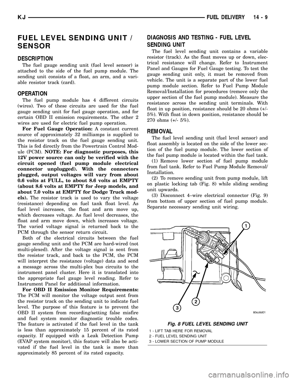
(2) To remove sending unit from pump module, lift
on plastic locking tab (Fig. 8) while sliding sending
unit upwards.
(3) Disconnect 4±wire electrical connector (Fig. 9)
from bottom of upper section of fuel pump module.
Separate necessary sending unit wiring.
Fig. 8 FUEL LEVEL SENDING UNIT
1 - LIFT TAB HERE FOR REMOVAL
2 - FUEL LEVEL SENDING UNIT
3 - LOWER SECTION OF PUMP MODULE
KJFUEL DELIVERY 14 - 9