2002 JEEP LIBERTY fused ignition switch
[x] Cancel search: fused ignition switchPage 731 of 1803

control stalk to a detent position selects the Off,
Delay, or On rear wiper system operating modes.
Rotating the control ring on the control stalk to
either of two Wash positions actuates the momentary
rear washer system switch. The multi-function
switch provides hard wired outputs to the rear wiper
module and the washer pump/motor unit for all rear
wiper and washer system functions.
The rear wiper and washer system will only oper-
ate when the ignition switch is in the Accessory or
On positions, and the rear flip-up glass and tailgate
ajar switches are closed. Battery current is directed
from a fuse in the Junction Block (JB) to the multi-
function switch through a fused ignition switch out-
put (run-acc) circuit. The internal circuitry of the
right (wiper) control stalk of the multi-function
switch then provides battery current signals through
a rear wiper on driver circuit and a rear wiper inter-
mittent driver circuit to the rear wiper module and
to the Body Control Module (BCM). The BCM uses
these rear wiper system inputs as a signal to lock the
rear flip-up glass and the tailgate to prevent the rear
flip-up glass or tailgate from being opened for as long
as the rear wiper is operating. The multi-function
switch circuitry also uses this battery current and a
ground circuit input to directly control the operation
and direction of the reversible electric washer pump/
motor unit.
A separate fuse in the JB provides battery current
to the electronic control circuitry of the rear wiper
module through a fused B(+) circuit. The rear wiper
module uses this fused B(+) input to park the rear
wiper blade off of the rear flip-up glass if the ignition
switch is turned to the Off position while the rear
wiper is operating, or if the ignition switch is turned
to the Off position before the rear wiper blade has
parked. However, if the ignition switch is turned to
the Off position while the rear wiper is operating,
then turned back On, the rear wiper switch must be
cycled to the Off position and back to the On or
Delay position before the rear wiper will operate
again. In addition, the rear wiper module receives an
input from the rear flip-up glass ajar switch on a
flip-up glass ajar switch sense circuit, which prevents
the rear wiper from operating when the flip-up glass
is not closed or fully latched.
The hard wired circuits and components of the rear
wiper and washer system may be diagnosed and
tested using conventional diagnostic tools and proce-
dures. Following are paragraphs that briefly describe
the operation of each of the rear wiper and washer
system operating modes.
CONTINUOUS WIPE MODE When the On posi-
tion of the control ring on the right (wiper) control
stalk of the multi-function switch is selected, the
multi-function switch circuitry directs a battery cur-rent signal to the rear wiper module through the
rear wiper on driver circuit, causing the rear wiper to
cycle continuously at a fixed speed.
INTERMITTENT WIPE MODE When the Delay
position of the control ring on the right (wiper) con-
trol stalk of the multi-function switch is selected, the
multi-function switch circuitry directs a battery cur-
rent signal to the rear wiper module through the
rear wiper intermittent driver circuit, causing the
rear wiper to cycle intermittently at a fixed delay
interval.
WASH MODE When the momentary Wash (after
On) position of the control ring on the right (wiper)
control stalk of the multi-function switch is selected,
the multi-function switch circuitry directs both bat-
tery current and ground to the washer pump/motor
unit, and a battery current signal to be provided to
the rear wiper module through the rear wiper on
driver circuit. This will cause the washer pump/mo-
tor unit to be energized and the rear wiper to cycle
continuously at a fixed speed for as long as the rear
Wash switch is held closed.
WIPE-AFTER-WASH MODE When the momentary
Wash (before Off) position of the control ring on the
right (wiper) control stalk of the multi-function
switch is selected, the multi-function switch circuitry
directs both battery current and ground to the
washer pump/motor unit, and a battery current sig-
nal to be provided to the rear wiper module through
the rear wiper on driver circuit. This will cause the
washer pump/motor unit to be energized and the rear
wiper to cycle continuously at a fixed speed for as
long as the rear Wash switch is held closed. When
the control ring is released to the Off position, the
washer pump/motor is de-energized, but the circuitry
within the rear wiper module will provide several
additional wipe cycles to complete the wipe-after-
wash mode cycle.
DIAGNOSIS AND TESTING - REAR WIPER &
WASHER SYSTEM
REAR WIPER SYSTEM
The diagnosis found here addresses an electrically
inoperative rear wiper system. If the rear wiper
motor operates, but the wiper does not move on the
rear flip-up glass, inspect the mechanical connection
between the rear wiper arm and the rear wiper
motor output shaft. If OK, replace the faulty rear
wiper module. If the wiper operates, but chatters,
lifts, or does not clear the glass, clean and inspect
the rear wiper system components as required. (Refer
to 8 - ELECTRICAL/REAR WIPERS/WASHERS -
INSPECTION) and (Refer to 8 - ELECTRICAL/
REAR WIPERS/WASHERS - CLEANING). Refer to
the appropriate wiring information. The wiring infor-
8R - 30 REAR WIPERS/WASHERSKJ
REAR WIPERS/WASHERS (Continued)
Page 732 of 1803

mation includes wiring diagrams, proper wire and
connector repair procedures, details of wire harness
routing and retention, connector pin-out information
and location views for the various wire harness con-
nectors, splices and grounds.
WARNING: ON VEHICLES EQUIPPED WITH AIR-
BAGS, DISABLE THE SUPPLEMENTAL RESTRAINT
SYSTEM BEFORE ATTEMPTING ANY STEERING
WHEEL, STEERING COLUMN, DRIVER AIRBAG,
PASSENGER AIRBAG, SEAT BELT TENSIONER,
SIDE CURTAIN AIRBAG, OR INSTRUMENT PANEL
COMPONENT DIAGNOSIS OR SERVICE. DISCON-
NECT AND ISOLATE THE BATTERY NEGATIVE
(GROUND) CABLE, THEN WAIT TWO MINUTES FOR
THE SYSTEM CAPACITOR TO DISCHARGE BEFORE
PERFORMING FURTHER DIAGNOSIS OR SERVICE.
THIS IS THE ONLY SURE WAY TO DISABLE THE
SUPPLEMENTAL RESTRAINT SYSTEM. FAILURE TO
TAKE THE PROPER PRECAUTIONS COULD
RESULT IN ACCIDENTAL AIRBAG DEPLOYMENT
AND POSSIBLE PERSONAL INJURY.
(1) Check that the interior lighting switch on the
left (lighting) control stalk of the multi-function
switch is not in the dome lamp disable position. With
all four doors and the tailgate closed, open the rear
flip-up glass. The interior lamps should light. Close
the rear flip-up glass. Note whether the interior
lamps remain lighted. They should turn off after
about thirty seconds. If OK, go to Step 2. If not OK,
go to Step 9.
(2) Check the fused B(+) fuse (Fuse 17 - 15
ampere) in the Junction Block (JB). If OK, go to Step
3. If not OK, repair the shorted circuit or component
as required and replace the faulty fuse.
(3) Check for battery voltage at the fused B(+) fuse
(Fuse 17 - 15 ampere) in the JB. If OK, go to Step 4.
If not OK, repair the open fused B(+) circuit between
the JB and the Power Distribution Center (PDC) as
required.
(4) Check the fused ignition switch output (run-
acc) fuse (Fuse 22 - 10 ampere) in the JB. If OK, go
to Step 5. If not OK, repair the shorted circuit or
component as required and replace the faulty fuse.
(5) Turn the ignition switch to the On position.
Check for battery voltage at the fused ignition switch
output (run-acc) fuse (Fuse 22 - 10 ampere) in the
JB. If OK, turn the ignition switch to the Off position
and go to Step 6. If not OK, repair the open fused
ignition switch output (run-acc) circuit between the
JB and the ignition switch as required.
(6) Disconnect and isolate the battery negative
cable. Disconnect the instrument panel wire harness
connector for the multi-function switch (Connector
C-2) from the switch connector receptacle. Reconnect
the battery negative cable. Turn the ignition switchto the On position. Check for battery voltage at the
fused ignition switch output (run-acc) circuit cavity of
the instrument panel wire harness connector for the
multi-function switch (Connector C-2). If OK, go to
Step 7. If not OK, repair the open fused ignition
switch output (run-acc) circuit between the multi-
function switch and the JB as required.
(7) Turn the ignition switch to the Off position.
Disconnect and isolate the battery negative cable.
Test the multi-function switch. (Refer to 8 - ELEC-
TRICAL/LAMPS/LIGHTING - EXTERIOR/MULTI-
FUNCTION SWITCH - DIAGNOSIS AND
TESTING). If the multi-function switch tests OK,
reconnect the instrument panel wire harness connec-
tors for the multi-function switch to the switch con-
nector receptacles and go to Step 8. If the multi-
function switch does not test OK, replace the faulty
switch.
(8) Remove the tailgate inner trim panel. Discon-
nect the tailgate wire harness connector for the rear
wiper module from the module connector receptacle.
Check for continuity between the ground circuit cav-
ity of the tailgate wire harness connector for the rear
wiper module and a good ground. There should be
continuity. If OK, go to Step 9. If not OK, repair the
open ground circuit to ground (G312) as required.
(9) Check for continuity between the flip-up glass
ajar switch sense circuit cavity of the tailgate wire
harness connector for the rear wiper module and a
good ground. There should be continuity with the
rear flip-up glass open, and no continuity with the
rear flip-up glass closed. If OK, go to Step 10. If not
OK, repair the open flip-up glass ajar circuit between
the rear wiper module and the flip-up glass ajar
switch as required.
(10) Reconnect the battery negative cable. Check
for battery voltage at the fused B(+) circuit cavity of
the tailgate wire harness connector for the rear wiper
module. If OK, go to Step 11. If not OK, repair the
open fused B(+) circuit between the rear wiper mod-
ule and the JB as required.
(11) Turn the ignition switch to the On position.
Turn the control ring on the right (wiper) control
stalk of the multi-function switch to the Delay posi-
tion. Check for battery voltage at the rear wiper
intermittent driver circuit cavity of the tailgate wire
harness connector for the rear wiper module. If OK,
go to Step 12. If not OK, repair the open rear wiper
intermittent driver circuit between the rear wiper
module and the multi-function switch as required.
(12) Turn the control ring on the right (wiper) con-
trol stalk of the multi-function switch to the On posi-
tion. Check for battery voltage at the rear wiper on
driver circuit cavity of the tailgate wire harness con-
nector for the rear wiper module. If OK, replace the
faulty rear wiper module. If not OK, repair the open
KJREAR WIPERS/WASHERS 8R - 31
REAR WIPERS/WASHERS (Continued)
Page 756 of 1803

STANDARD PROCEDURE - TESTING FOR A
SHORT TO GROUND
(1) Remove the fuse and disconnect all items
involved with the fuse.
(2) Connect a test light or a voltmeter across the
terminals of the fuse.
(3) Starting at the fuse block, wiggle the wiring
harness about six to eight inches apart and watch
the voltmeter/test lamp.
(4) If the voltmeter registers voltage or the test
lamp glows, there is a short to ground in that gen-
eral area of the wiring harness.
STANDARD PROCEDURE - TESTING FOR A
SHORT TO GROUND ON FUSES POWERING
SEVERAL LOADS
(1) Refer to the wiring diagrams and disconnect or
isolate all items on the suspected fused circuits.
(2) Replace the blown fuse.
(3) Supply power to the fuse by turning ON the
ignition switch or re-connecting the battery.
(4) Start connecting or energizing the items in the
fuse circuit one at a time. When the fuse blows the
circuit with the short to ground has been isolated.
STANDARD PROCEDURE - TESTING FOR A
VOLTAGE DROP
(1) Connect the positive lead of the voltmeter to
the side of the circuit closest to the battery (Fig. 9).
(2) Connect the other lead of the voltmeter to the
other side of the switch, component or circuit.
(3) Operate the item.
(4) The voltmeter will show the difference in volt-
age between the two points.
Fig. 8 TESTING FOR CONTINUITY
1 - FUSE REMOVED FROM CIRCUIT
Fig. 9 TESTING FOR VOLTAGE DROP
KJ8W-01 WIRING DIAGRAM INFORMATION8Wa-01-9
WIRING DIAGRAM INFORMATION (Continued)
Page 1061 of 1803
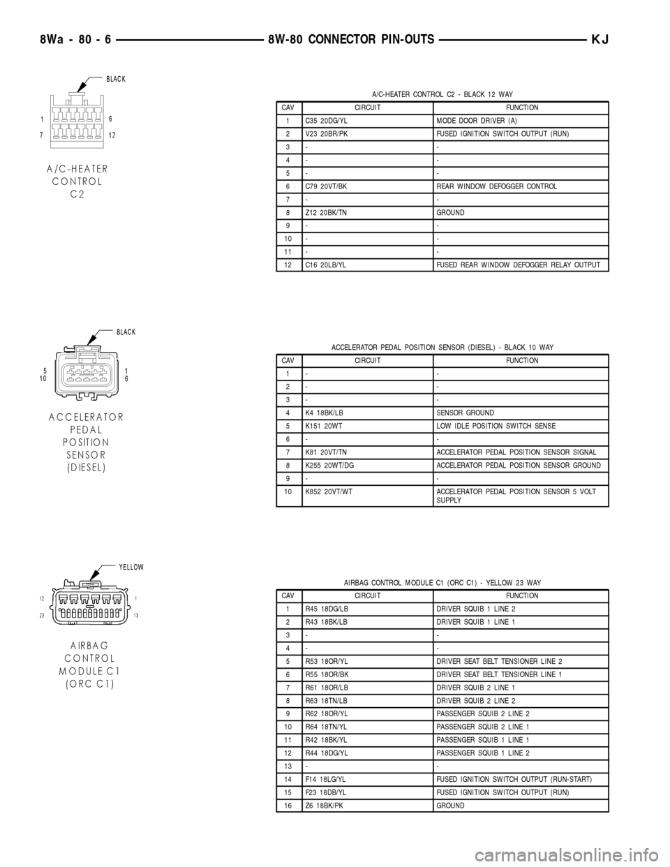
A/C-HEATER CONTROL C2 - BLACK 12 WAY
CAV CIRCUIT FUNCTION
1 C35 20DG/YL MODE DOOR DRIVER (A)
2 V23 20BR/PK FUSED IGNITION SWITCH OUTPUT (RUN)
3- -
4- -
5- -
6 C79 20VT/BK REAR WINDOW DEFOGGER CONTROL
7- -
8 Z12 20BK/TN GROUND
9- -
10 - -
11 - -
12 C16 20LB/YL FUSED REAR WINDOW DEFOGGER RELAY OUTPUT
ACCELERATOR PEDAL POSITION SENSOR (DIESEL) - BLACK 10 WAY
CAV CIRCUIT FUNCTION
1- -
2- -
3- -
4 K4 18BK/LB SENSOR GROUND
5 K151 20WT LOW IDLE POSITION SWITCH SENSE
6- -
7 K81 20VT/TN ACCELERATOR PEDAL POSITION SENSOR SIGNAL
8 K255 20WT/DG ACCELERATOR PEDAL POSITION SENSOR GROUND
9- -
10 K852 20VT/WT ACCELERATOR PEDAL POSITION SENSOR 5 VOLT
SUPPLY
AIRBAG CONTROL MODULE C1 (ORC C1) - YELLOW 23 WAY
CAV CIRCUIT FUNCTION
1 R45 18DG/LB DRIVER SQUIB 1 LINE 2
2 R43 18BK/LB DRIVER SQUIB 1 LINE 1
3- -
4- -
5 R53 18OR/YL DRIVER SEAT BELT TENSIONER LINE 2
6 R55 18OR/BK DRIVER SEAT BELT TENSIONER LINE 1
7 R61 18OR/LB DRIVER SQUIB 2 LINE 1
8 R63 18TN/LB DRIVER SQUIB 2 LINE 2
9 R62 18OR/YL PASSENGER SQUIB 2 LINE 2
10 R64 18TN/YL PASSENGER SQUIB 2 LINE 1
11 R42 18BK/YL PASSENGER SQUIB 1 LINE 1
12 R44 18DG/YL PASSENGER SQUIB 1 LINE 2
13 - -
14 F14 18LG/YL FUSED IGNITION SWITCH OUTPUT (RUN-START)
15 F23 18DB/YL FUSED IGNITION SWITCH OUTPUT (RUN)
16 Z6 18BK/PK GROUND
8Wa - 80 - 6 8W-80 CONNECTOR PIN-OUTSKJ
Page 1063 of 1803
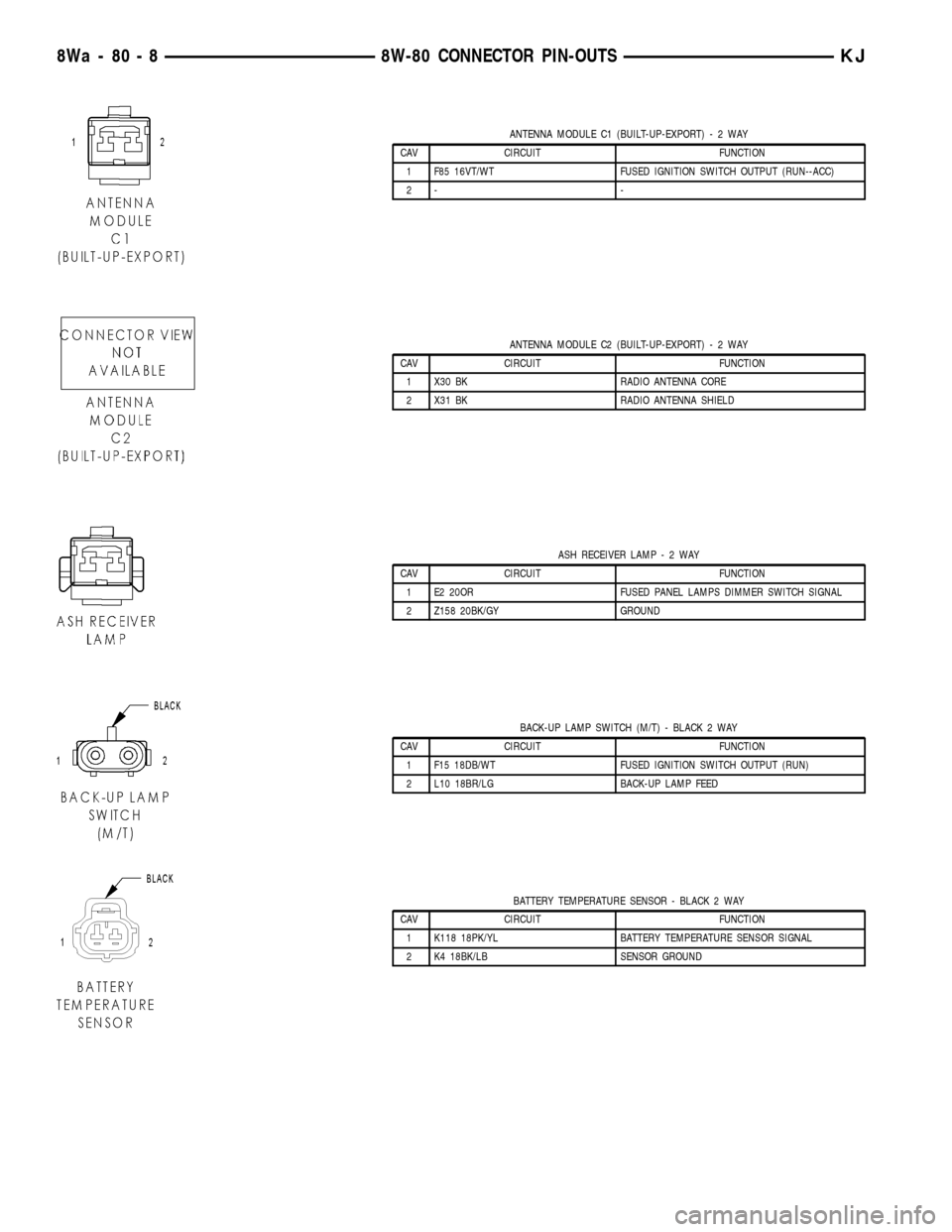
ANTENNA MODULE C1 (BUILT-UP-EXPORT)-2WAY
CAV CIRCUIT FUNCTION
1 F85 16VT/WT FUSED IGNITION SWITCH OUTPUT (RUN--ACC)
2- -
ANTENNA MODULE C2 (BUILT-UP-EXPORT)-2WAY
CAV CIRCUIT FUNCTION
1 X30 BK RADIO ANTENNA CORE
2 X31 BK RADIO ANTENNA SHIELD
ASH RECEIVER LAMP-2WAY
CAV CIRCUIT FUNCTION
1 E2 20OR FUSED PANEL LAMPS DIMMER SWITCH SIGNAL
2 Z158 20BK/GY GROUND
BACK-UP LAMP SWITCH (M/T) - BLACK 2 WAY
CAV CIRCUIT FUNCTION
1 F15 18DB/WT FUSED IGNITION SWITCH OUTPUT (RUN)
2 L10 18BR/LG BACK-UP LAMP FEED
BATTERY TEMPERATURE SENSOR - BLACK 2 WAY
CAV CIRCUIT FUNCTION
1 K118 18PK/YL BATTERY TEMPERATURE SENSOR SIGNAL
2 K4 18BK/LB SENSOR GROUND
8Wa - 80 - 8 8W-80 CONNECTOR PIN-OUTSKJ
Page 1064 of 1803
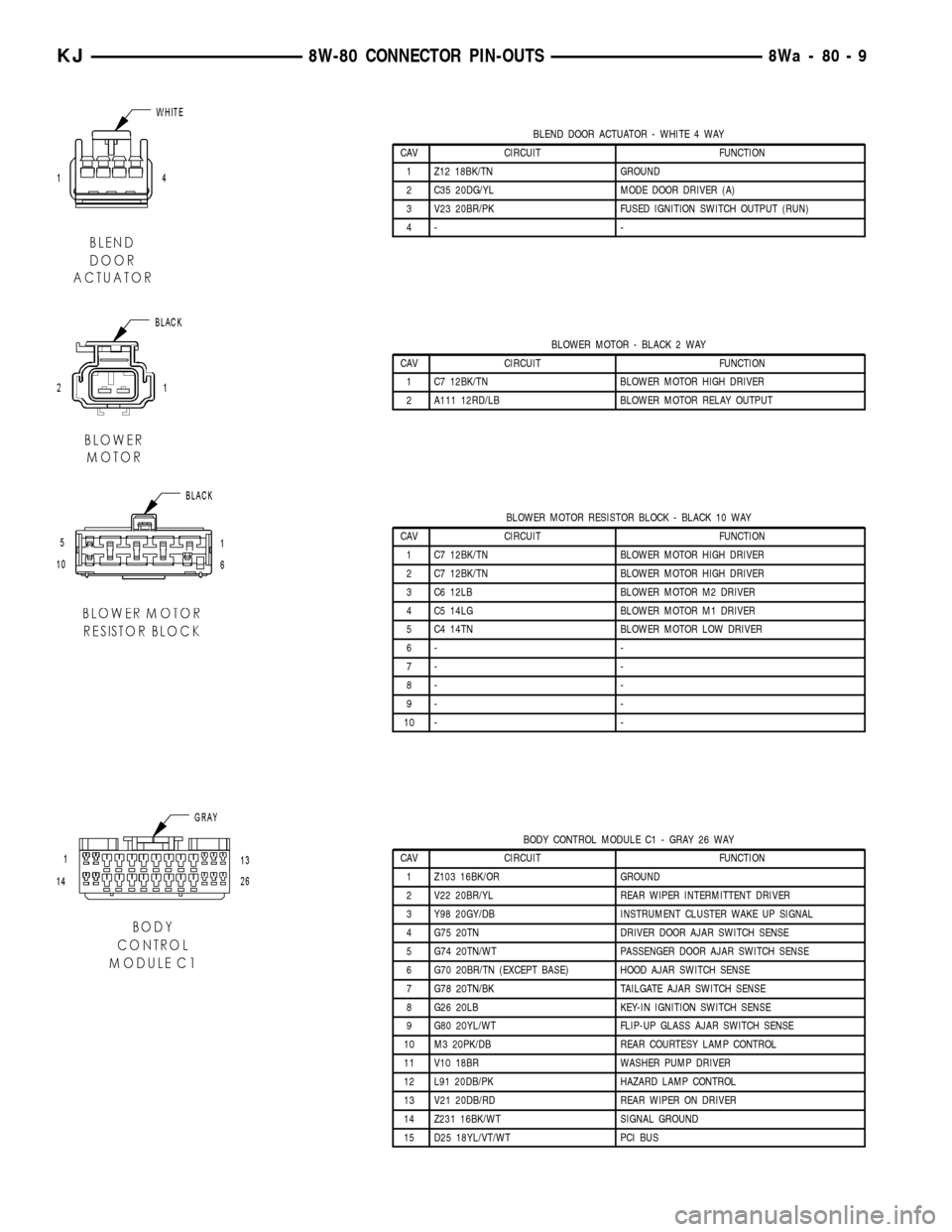
BLEND DOOR ACTUATOR - WHITE 4 WAY
CAV CIRCUIT FUNCTION
1 Z12 18BK/TN GROUND
2 C35 20DG/YL MODE DOOR DRIVER (A)
3 V23 20BR/PK FUSED IGNITION SWITCH OUTPUT (RUN)
4- -
BLOWER MOTOR - BLACK 2 WAY
CAV CIRCUIT FUNCTION
1 C7 12BK/TN BLOWER MOTOR HIGH DRIVER
2 A111 12RD/LB BLOWER MOTOR RELAY OUTPUT
BLOWER MOTOR RESISTOR BLOCK - BLACK 10 WAY
CAV CIRCUIT FUNCTION
1 C7 12BK/TN BLOWER MOTOR HIGH DRIVER
2 C7 12BK/TN BLOWER MOTOR HIGH DRIVER
3 C6 12LB BLOWER MOTOR M2 DRIVER
4 C5 14LG BLOWER MOTOR M1 DRIVER
5 C4 14TN BLOWER MOTOR LOW DRIVER
6- -
7- -
8- -
9- -
10 - -
BODY CONTROL MODULE C1 - GRAY 26 WAY
CAV CIRCUIT FUNCTION
1 Z103 16BK/OR GROUND
2 V22 20BR/YL REAR WIPER INTERMITTENT DRIVER
3 Y98 20GY/DB INSTRUMENT CLUSTER WAKE UP SIGNAL
4 G75 20TN DRIVER DOOR AJAR SWITCH SENSE
5 G74 20TN/WT PASSENGER DOOR AJAR SWITCH SENSE
6 G70 20BR/TN (EXCEPT BASE) HOOD AJAR SWITCH SENSE
7 G78 20TN/BK TAILGATE AJAR SWITCH SENSE
8 G26 20LB KEY-IN IGNITION SWITCH SENSE
9 G80 20YL/WT FLIP-UP GLASS AJAR SWITCH SENSE
10 M3 20PK/DB REAR COURTESY LAMP CONTROL
11 V10 18BR WASHER PUMP DRIVER
12 L91 20DB/PK HAZARD LAMP CONTROL
13 V21 20DB/RD REAR WIPER ON DRIVER
14 Z231 16BK/WT SIGNAL GROUND
15 D25 18YL/VT/WT PCI BUS
KJ8W-80 CONNECTOR PIN-OUTS8Wa-80-9
Page 1066 of 1803
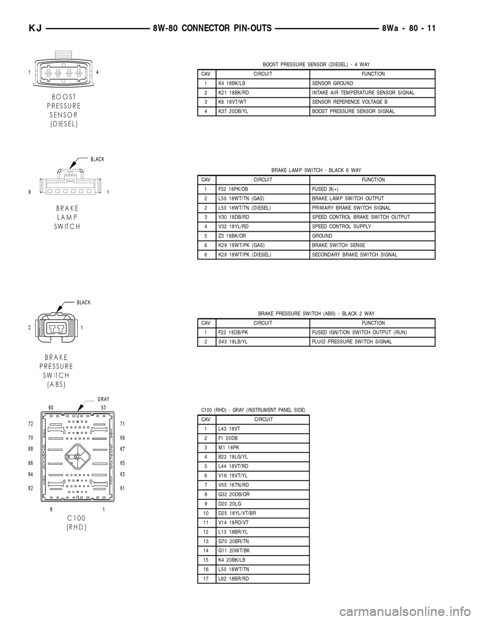
BOOST PRESSURE SENSOR (DIESEL)-4WAY
CAV CIRCUIT FUNCTION
1 K4 18BK/LB SENSOR GROUND
2 K21 18BK/RD INTAKE AIR TEMPERATURE SENSOR SIGNAL
3 K6 18VT/WT SENSOR REFERENCE VOLTAGE B
4 K37 20DB/YL BOOST PRESSURE SENSOR SIGNAL
BRAKE LAMP SWITCH - BLACK 6 WAY
CAV CIRCUIT FUNCTION
1 F32 18PK/DB FUSED B(+)
2 L50 18WT/TN (GAS) BRAKE LAMP SWITCH OUTPUT
2 L50 18WT/TN (DIESEL) PRIMARY BRAKE SWITCH SIGNAL
3 V30 18DB/RD SPEED CONTROL BRAKE SWITCH OUTPUT
4 V32 18YL/RD SPEED CONTROL SUPPLY
5 Z3 18BK/OR GROUND
6 K29 18WT/PK (GAS) BRAKE SWITCH SENSE
6 K29 18WT/PK (DIESEL) SECONDARY BRAKE SWITCH SIGNAL
BRAKE PRESSURE SWITCH (ABS) - BLACK 2 WAY
CAV CIRCUIT FUNCTION
1 F22 18DB/PK FUSED IGNITION SWITCH OUTPUT (RUN)
2 S43 18LB/YL FLUID PRESSURE SWITCH SIGNAL
C100 (RHD) - GRAY (INSTRUMENT PANEL SIDE)
CAV CIRCUIT
1 L43 18VT
2 F1 20DB
3 M1 18PK
4 B22 18LG/YL
5 L44 18VT/RD
6 V16 18VT/YL
7 V55 16TN/RD
8 G32 20DB/OR
9 D20 20LG
10 D25 18YL/VT/BR
11 V14 18RD/VT
12 L13 18BR/YL
13 G70 20BR/TN
14 G11 20WT/BK
15 K4 20BK/LB
16 L50 18WT/TN
17 L62 18BR/RD
KJ8W-80 CONNECTOR PIN-OUTS8Wa-80-11
Page 1103 of 1803
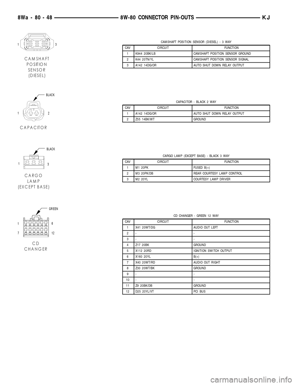
CAMSHAFT POSITION SENSOR (DIESEL)-3WAY
CAV CIRCUIT FUNCTION
1 K944 20BK/LB CAMSHAFT POSITION SENSOR GROUND
2 K44 20TN/YL CAMSHAFT POSITION SENSOR SIGNAL
3 A142 14DG/OR AUTO SHUT DOWN RELAY OUTPUT
CAPACITOR - BLACK 2 WAY
CAV CIRCUIT FUNCTION
1 A142 14DG/OR AUTO SHUT DOWN RELAY OUTPUT
2 Z55 14BK/WT GROUND
CARGO LAMP (EXCEPT BASE) - BLACK 3 WAY
CAV CIRCUIT FUNCTION
1 M1 20PK FUSED B(+)
2 M3 20PK/DB REAR COURTESY LAMP CONTROL
3 M2 20YL COURTESY LAMP DRIVER
CD CHANGER - GREEN 12 WAY
CAV CIRCUIT FUNCTION
1 X41 20WT/DG AUDIO OUT LEFT
2- -
3- -
4 Z17 20BK GROUND
5 X112 20RD IGNITION SWITCH OUTPUT
6 X160 20YL B(+)
7 X40 20WT/RD AUDIO OUT RIGHT
8 Z30 20WT/BK GROUND
9- -
10 - -
11 Z9 20BK/DB GROUND
12 D25 20YL/VT PCI BUS
8Wa - 80 - 48 8W-80 CONNECTOR PIN-OUTSKJ