2002 JEEP LIBERTY fused ignition switch
[x] Cancel search: fused ignition switchPage 1148 of 1803
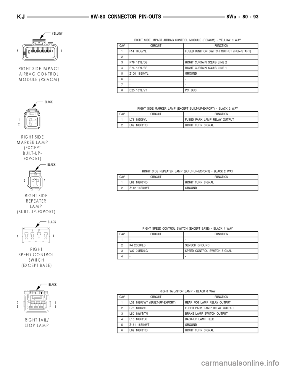
RIGHT SIDE IMPACT AIRBAG CONTROL MODULE (RSIACM) - YELLOW 8 WAY
CAV CIRCUIT FUNCTION
1 F14 18LG/YL FUSED IGNITION SWITCH OUTPUT (RUN-START)
2- -
3 R76 18YL/DB RIGHT CURTAIN SQUIB LINE 2
4 R74 18YL/BR RIGHT CURTAIN SQUIB LINE 1
5 Z100 18BK/YL GROUND
6- -
7- -
8 D25 18YL/VT PCI BUS
RIGHT SIDE MARKER LAMP (EXCEPT BUILT-UP-EXPORT) - BLACK 2 WAY
CAV CIRCUIT FUNCTION
1 L78 18DG/YL FUSED PARK LAMP RELAY OUTPUT
2 L62 18BR/RD RIGHT TURN SIGNAL
RIGHT SIDE REPEATER LAMP (BUILT-UP-EXPORT) - BLACK 2 WAY
CAV CIRCUIT FUNCTION
1 L62 18BR/RD RIGHT TURN SIGNAL
2 Z142 18BK/WT GROUND
RIGHT SPEED CONTROL SWITCH (EXCEPT BASE) - BLACK 4 WAY
CAV CIRCUIT FUNCTION
1- -
2 K4 20BK/LB SENSOR GROUND
3 V37 20RD/LG SPEED CONTROL SWITCH SIGNAL
4- -
RIGHT TAIL/STOP LAMP - BLACK 6 WAY
CAV CIRCUIT FUNCTION
1 L38 18BR/WT (BUILT-UP-EXPORT) REAR FOG LAMP RELAY OUTPUT
2 L78 18DG/YL FUSED PARK LAMP RELAY OUTPUT
3 L50 18WT/TN BRAKE LAMP SWITCH OUTPUT
4 L10 18BR/LG BACK-UP LAMP FEED
5 Z151 18BK/WT GROUND
6 L62 18BR/RD RIGHT TURN SIGNAL
KJ8W-80 CONNECTOR PIN-OUTS8Wa-80-93
Page 1149 of 1803
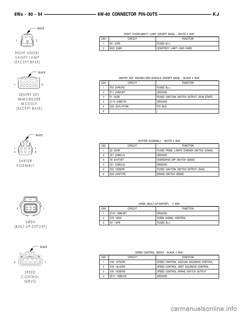
RIGHT VISOR/VANITY LAMP (EXCEPT BASE) - WHITE 2 WAY
CAV CIRCUIT FUNCTION
1 M1 20PK FUSED B(+)
2 M20 20BR COURTESY LAMP LOAD SHED
SENTRY KEY IMMOBILIZER MODULE (EXCEPT BASE) - BLACK 6 WAY
CAV CIRCUIT FUNCTION
1 F33 20PK/RD FUSED B(+)
2 Z11 20BK/WT GROUND
3 F1 20DB FUSED IGNITION SWITCH OUTPUT (RUN-START)
4 Z110 20BK/TN GROUND
5 D25 20YL/VT/BK PCI BUS
6- -
SHIFTER ASSEMBLY - WHITE 6 WAY
CAV CIRCUIT FUNCTION
1 E2 20OR FUSED PANEL LAMPS DIMMER SWITCH SIGNAL
2 Z21 20BK/LG GROUND
3 T6 20VT/WT OVERDRIVE OFF SWITCH SENSE
4 Z21 20BK/LG GROUND
5 F22 18DB/PK FUSED IGNITION SWITCH OUTPUT (RUN)
6 K29 20WT/PK BRAKE SWITCH SENSE
SIREN (BUILT-UP-EXPORT)-3WAY
CAV CIRCUIT FUNCTION
1 Z142 18BK/WT GROUND
2 X75 18DG SIREN SIGNAL CONTROL
3 M1 18PK FUSED B(+)
SPEED CONTROL SERVO - BLACK 4 WAY
CAV CIRCUIT FUNCTION
1 V36 18TN/RD SPEED CONTROL VACUUM SOLENOID CONTROL
2 V35 18LG/RD SPEED CONTROL VENT SOLENOID CONTROL
3 V30 18DB/RD SPEED CONTROL BRAKE SWITCH OUTPUT
4 Z212 18BK/OR GROUND
8Wa - 80 - 94 8W-80 CONNECTOR PIN-OUTSKJ
Page 1150 of 1803
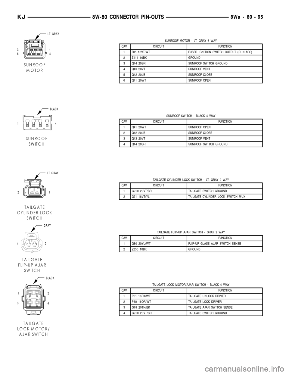
SUNROOF MOTOR - LT. GRAY 6 WAY
CAV CIRCUIT FUNCTION
1 F85 16VT/WT FUSED IGNITION SWITCH OUTPUT (RUN-ACC)
2 Z111 16BK GROUND
3 Q44 20BR SUNROOF SWITCH GROUND
4 Q43 20VT SUNROOF VENT
5 Q42 20LB SUNROOF CLOSE
6 Q41 20WT SUNROOF OPEN
SUNROOF SWITCH - BLACK 4 WAY
CAV CIRCUIT FUNCTION
1 Q41 20WT SUNROOF OPEN
2 Q42 20LB SUNROOF CLOSE
3 Q43 20VT SUNROOF VENT
4 Q44 20BR SUNROOF SWITCH GROUND
TAILGATE CYLINDER LOCK SWITCH - LT. GRAY 2 WAY
CAV CIRCUIT FUNCTION
1 G910 20VT/BR TAILGATE SWITCH GROUND
2 G71 18VT/YL TAILGATE CYLINDER LOCK SWITCH MUX
TAILGATE FLIP-UP AJAR SWITCH - GRAY 2 WAY
CAV CIRCUIT FUNCTION
1 G80 20YL/WT FLIP-UP GLASS AJAR SWITCH SENSE
2 Z235 18BK GROUND
TAILGATE LOCK MOTOR/AJAR SWITCH - BLACK 4 WAY
CAV CIRCUIT FUNCTION
1 P31 16PK/WT TAILGATE UNLOCK DRIVER
2 P30 16OR/WT TAILGATE LOCK DRIVER
3 G78 20TN/BK TAILGATE AJAR SWITCH SENSE
4 G910 20VT/BR TAILGATE SWITCH GROUND
KJ8W-80 CONNECTOR PIN-OUTS8Wa-80-95
Page 1152 of 1803
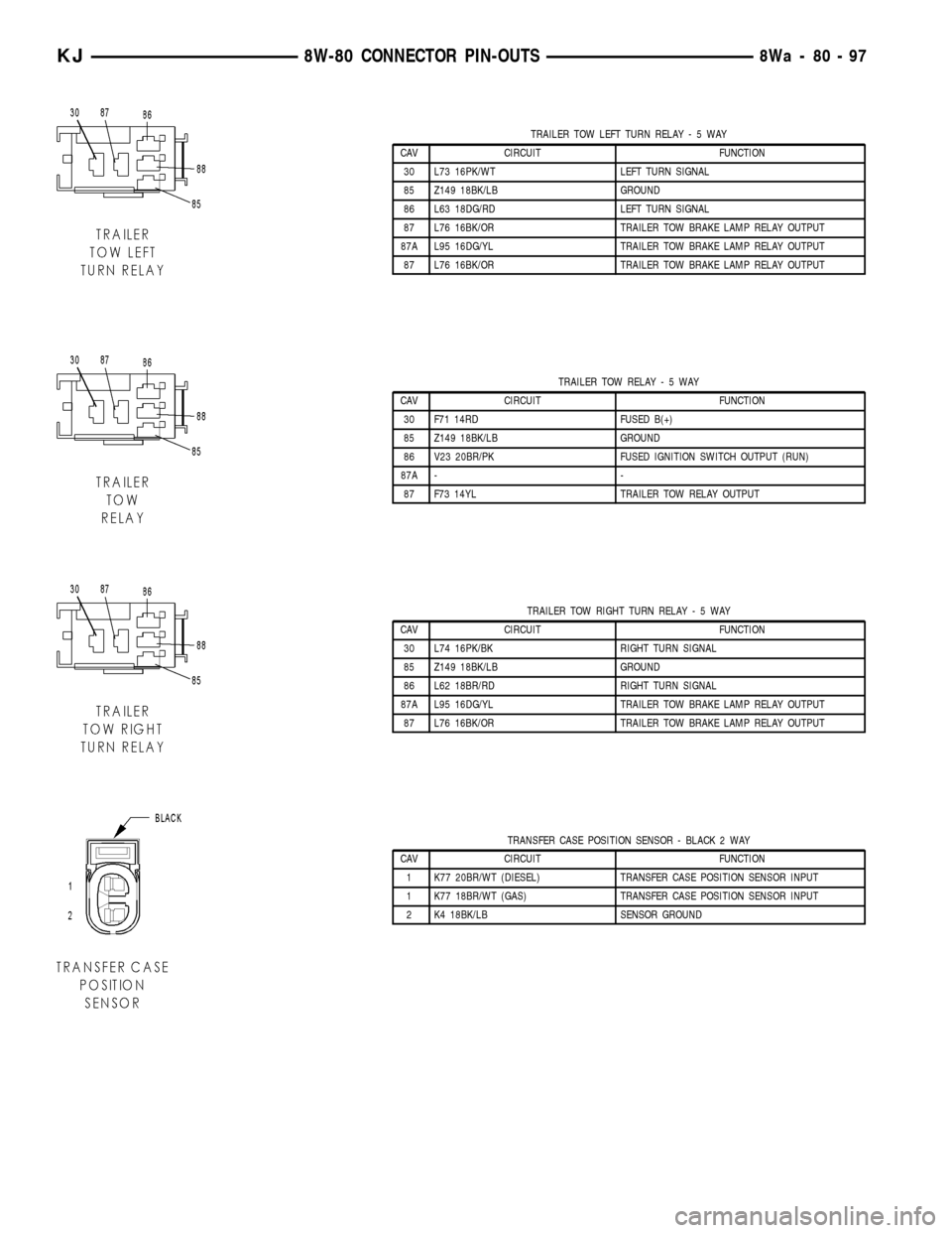
TRAILER TOW LEFT TURN RELAY-5WAY
CAV CIRCUIT FUNCTION
30 L73 16PK/WT LEFT TURN SIGNAL
85 Z149 18BK/LB GROUND
86 L63 18DG/RD LEFT TURN SIGNAL
87 L76 16BK/OR TRAILER TOW BRAKE LAMP RELAY OUTPUT
87A L95 16DG/YL TRAILER TOW BRAKE LAMP RELAY OUTPUT
87 L76 16BK/OR TRAILER TOW BRAKE LAMP RELAY OUTPUT
TRAILER TOW RELAY-5WAY
CAV CIRCUIT FUNCTION
30 F71 14RD FUSED B(+)
85 Z149 18BK/LB GROUND
86 V23 20BR/PK FUSED IGNITION SWITCH OUTPUT (RUN)
87A - -
87 F73 14YL TRAILER TOW RELAY OUTPUT
TRAILER TOW RIGHT TURN RELAY-5WAY
CAV CIRCUIT FUNCTION
30 L74 16PK/BK RIGHT TURN SIGNAL
85 Z149 18BK/LB GROUND
86 L62 18BR/RD RIGHT TURN SIGNAL
87A L95 16DG/YL TRAILER TOW BRAKE LAMP RELAY OUTPUT
87 L76 16BK/OR TRAILER TOW BRAKE LAMP RELAY OUTPUT
TRANSFER CASE POSITION SENSOR - BLACK 2 WAY
CAV CIRCUIT FUNCTION
1 K77 20BR/WT (DIESEL) TRANSFER CASE POSITION SENSOR INPUT
1 K77 18BR/WT (GAS) TRANSFER CASE POSITION SENSOR INPUT
2 K4 18BK/LB SENSOR GROUND
KJ8W-80 CONNECTOR PIN-OUTS8Wa-80-97
Page 1153 of 1803
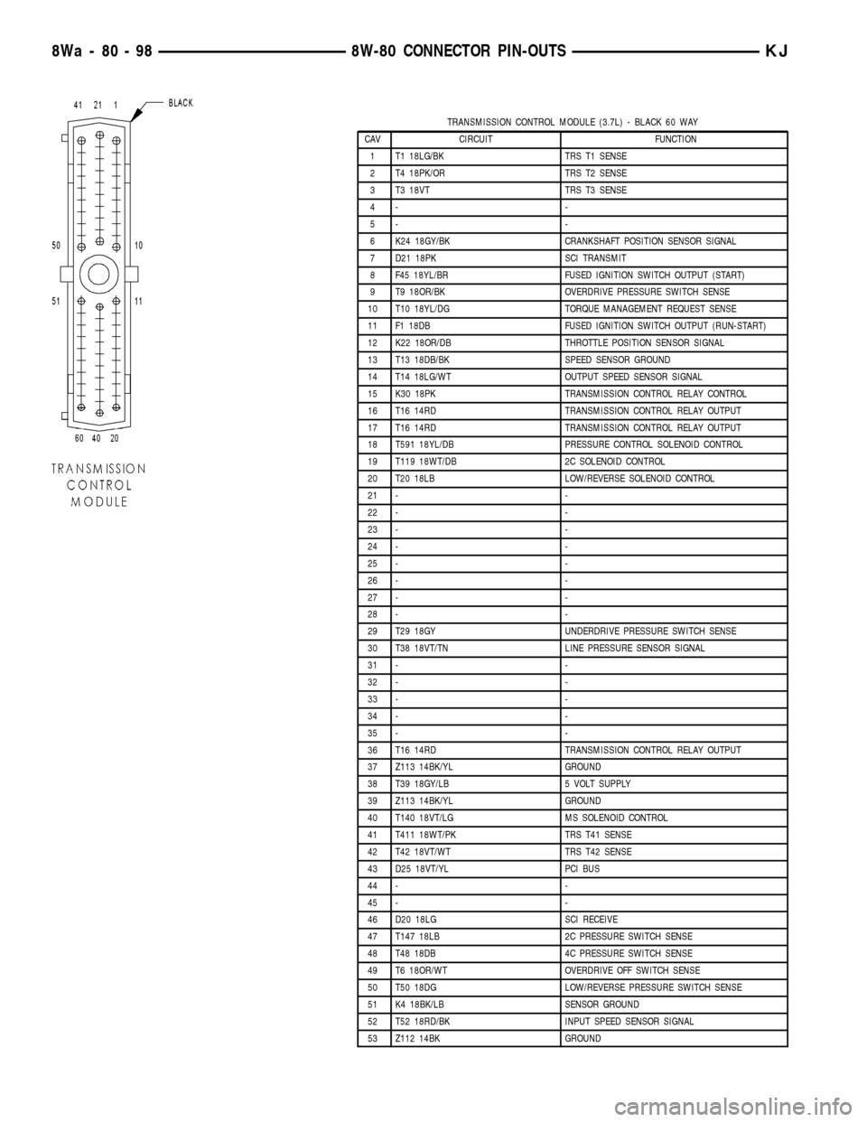
TRANSMISSION CONTROL MODULE (3.7L) - BLACK 60 WAY
CAV CIRCUIT FUNCTION
1 T1 18LG/BK TRS T1 SENSE
2 T4 18PK/OR TRS T2 SENSE
3 T3 18VT TRS T3 SENSE
4- -
5- -
6 K24 18GY/BK CRANKSHAFT POSITION SENSOR SIGNAL
7 D21 18PK SCI TRANSMIT
8 F45 18YL/BR FUSED IGNITION SWITCH OUTPUT (START)
9 T9 18OR/BK OVERDRIVE PRESSURE SWITCH SENSE
10 T10 18YL/DG TORQUE MANAGEMENT REQUEST SENSE
11 F1 18DB FUSED IGNITION SWITCH OUTPUT (RUN-START)
12 K22 18OR/DB THROTTLE POSITION SENSOR SIGNAL
13 T13 18DB/BK SPEED SENSOR GROUND
14 T14 18LG/WT OUTPUT SPEED SENSOR SIGNAL
15 K30 18PK TRANSMISSION CONTROL RELAY CONTROL
16 T16 14RD TRANSMISSION CONTROL RELAY OUTPUT
17 T16 14RD TRANSMISSION CONTROL RELAY OUTPUT
18 T591 18YL/DB PRESSURE CONTROL SOLENOID CONTROL
19 T119 18WT/DB 2C SOLENOID CONTROL
20 T20 18LB LOW/REVERSE SOLENOID CONTROL
21 - -
22 - -
23 - -
24 - -
25 - -
26 - -
27 - -
28 - -
29 T29 18GY UNDERDRIVE PRESSURE SWITCH SENSE
30 T38 18VT/TN LINE PRESSURE SENSOR SIGNAL
31 - -
32 - -
33 - -
34 - -
35 - -
36 T16 14RD TRANSMISSION CONTROL RELAY OUTPUT
37 Z113 14BK/YL GROUND
38 T39 18GY/LB 5 VOLT SUPPLY
39 Z113 14BK/YL GROUND
40 T140 18VT/LG MS SOLENOID CONTROL
41 T411 18WT/PK TRS T41 SENSE
42 T42 18VT/WT TRS T42 SENSE
43 D25 18VT/YL PCI BUS
44 - -
45 - -
46 D20 18LG SCI RECEIVE
47 T147 18LB 2C PRESSURE SWITCH SENSE
48 T48 18DB 4C PRESSURE SWITCH SENSE
49 T6 18OR/WT OVERDRIVE OFF SWITCH SENSE
50 T50 18DG LOW/REVERSE PRESSURE SWITCH SENSE
51 K4 18BK/LB SENSOR GROUND
52 T52 18RD/BK INPUT SPEED SENSOR SIGNAL
53 Z112 14BK GROUND
8Wa - 80 - 98 8W-80 CONNECTOR PIN-OUTSKJ
Page 1154 of 1803
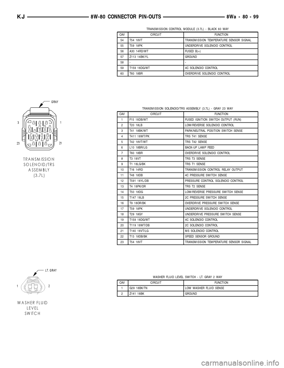
TRANSMISSION CONTROL MODULE (3.7L) - BLACK 60 WAY
CAV CIRCUIT FUNCTION
54 T54 18VT TRANSMISSION TEMPERATURE SENSOR SIGNAL
55 T59 18PK UNDERDRIVE SOLENOID CONTROL
56 A30 14RD/WT FUSED B(+)
57 Z113 14BK/YL GROUND
58 - -
59 T159 18DG/WT 4C SOLENOID CONTROL
60 T60 18BR OVERDRIVE SOLENOID CONTROL
TRANSMISSION SOLENOID/TRS ASSEMBLY (3.7L) - GRAY 23 WAY
CAV CIRCUIT FUNCTION
1 F15 18DB/WT FUSED IGNITION SWITCH OUTPUT (RUN)
2 T20 18LB LOW/REVERSE SOLENOID CONTROL
3 T41 18BK/WT PARK/NEUTRAL POSITION SWITCH SENSE
4 T411 18WT/PK TRS T41 SENSE
5 T42 18VT/WT TRS T42 SENSE
6 L10 18BR/LG BACK-UP LAMP FEED
7 T60 18BR OVERDRIVE SOLENOID CONTROL
8 T3 18VT TRS T3 SENSE
9 T1 18LG/BK TRS T1 SENSE
10 T16 14RD TRANSMISSION CONTROL RELAY OUTPUT
11 T48 18DB 4C PRESSURE SWITCH SENSE
12 T591 18YL/DB PRESSURE CONTROL SOLENOID CONTROL
13 T4 18PK/OR TRS T2 SENSE
14 T50 18DG LOW/REVERSE PRESSURE SWITCH SENSE
15 T147 18LB 2C PRESSURE SWITCH SENSE
16 T9 18OR/BK OVERDRIVE PRESSURE SWITCH SENSE
17 T59 18PK UNDERDRIVE SOLENOID CONTROL
18 T29 18GY UNDERDRIVE PRESSURE SWITCH SENSE
19 T159 18DG/WT 4C SOLENOID CONTROL
20 T119 18WT/DB 2C SOLENOID CONTROL
21 T140 18VT/LG MS SOLENOID CONTROL
22 T13 18DB/BK SPEED SENSOR GROUND
23 T54 18VT TRANSMISSION TEMPERATURE SENSOR SIGNAL
WASHER FLUID LEVEL SWITCH - LT. GRAY 2 WAY
CAV CIRCUIT FUNCTION
1 G29 18BK/TN LOW WASHER FLUID SENSE
2 Z141 18BK GROUND
KJ8W-80 CONNECTOR PIN-OUTS8Wa-80-99
Page 1668 of 1803

(2) Resistance between terminals 85 and 86 (elec-
tromagnet) should be 67.5 to 82.5 ohms. If OK, go to
Step 3. If not OK, replace the faulty relay.
(3) Connect a battery to terminals 85 and 86.
There should now be continuity between terminals
30 and 87, and no continuity between terminals 87A
and 30. If OK, see Relay Circuit Test. If not OK,
replace the faulty relay.
RELAY CIRCUIT TEST
For circuit descriptions and diagrams, (Refer to
Appropriate Wiring Information).
(1) The relay common feed terminal cavity (30) is
connected to fused battery feed. There should be bat-
tery voltage at the cavity for relay terminal 30 at all
times. If OK, go to Step 2. If not OK, repair the open
circuit to the fuse in the PDC as required.
(2) The relay normally closed terminal (87A) is not
used in this application. Go to Step 3.
(3) The relay normally open terminal cavity (87) is
connected to the compressor clutch coil. There should
be continuity between this cavity and the A/C com-
pressor clutch relay output circuit cavity of the com-
pressor clutch coil wire harness connector. If OK, go
to Step 4. If not OK, repair the open circuit as
required.
(4) The relay coil battery terminal (86) is con-
nected to the fused ignition switch output (run/start)circuit. There should be battery voltage at the cavity
for relay terminal 86 with the ignition switch in the
On position. If OK, go to Step 5. If not OK, repair the
open circuit to the fuse in the junction block as
required.
(5) The coil ground terminal cavity (85) is switched
to ground through the Powertrain Control Module
(PCM). There should be continuity between this cav-
ity and the A/C compressor clutch relay control cir-
cuit cavity of the PCM wire harness connector C
(gray) at all times. If not OK, repair the open circuit
as required.
REMOVAL
(1) Disconnect and isolate the battery negative
cable.
(2) Remove the cover from the Power Distribution
Center (PDC).
(3) Refer to the label on the PDC for compressor
clutch relay identification and location.
(4) Unplug the compressor clutch relay from the
PDC.
INSTALLATION
(1) Install the compressor clutch relay by aligning
the relay terminals with the cavities in the PDC and
pushing the relay firmly into place.
(2) Install the PDC cover.
(3) Connect the battery negative cable.
(4) Test the relay operation.
A/C HEATER CONTROL
DESCRIPTION
Both the heater-only and A/C heater systems use a
combination of mechanical, electrical, and vacuum
controls. These controls provide the vehicle operator
with a number of setting options to help control the
climate and comfort within the vehicle. Refer to the
owner's manual in the vehicle glove box for more
information on the features, use, and suggested oper-
ation of these controls.
The heater-only or A/C heater control panel is
located to the right of the instrument cluster on the
instrument panel. The control panel contains a rota-
ry-type temperature control knob, a rotary-type mode
control switch knob, and a rotary-type blower motor
speed switch knob. The control also has a push but-
ton to activate the rear window defogger.
The heater-only or A/C heater control panel cannot
be repaired. If faulty or damaged, the entire unit
must be replaced. The illumination lamps are avail-
able for service replacement.
Fig. 10 COMPRESSOR CLUTCH RELAY
30 - COMMON FEED
85 - COIL GROUND
86 - COIL BATTERY
87 - NORMALLY OPEN
87A - NORMALLY CLOSED
24 - 16 CONTROLSKJ
A/C COMPRESSOR CLUTCH RELAY (Continued)
Page 1673 of 1803

DIAGNOSIS AND TESTING - BLOWER MOTOR
RELAY
WARNING: ON VEHICLES EQUIPPED WITH AIR-
BAGS, DISABLE THE AIRBAG SYSTEM BEFORE
ATTEMPTING ANY STEERING WHEEL, STEERING
COLUMN, OR INSTRUMENT PANEL COMPONENT
DIAGNOSIS OR SERVICE. DISCONNECT AND ISO-
LATE THE BATTERY NEGATIVE (GROUND) CABLE,
THEN WAIT TWO MINUTES FOR THE AIRBAG SYS-
TEM CAPACITOR TO DISCHARGE BEFORE PER-
FORMING FURTHER DIAGNOSIS OR SERVICE. THIS
IS THE ONLY SURE WAY TO DISABLE THE AIRBAG
SYSTEM. FAILURE TO TAKE THE PROPER PRE-
CAUTIONS COULD RESULT IN AN ACCIDENTAL
AIRBAG DEPLOYMENT AND POSSIBLE PERSONAL
INJURY.
RELAY TEST
The blower motor relay (Fig. 15) is located in the
PDC which is located under the hood.. Remove the
relay from the PDC to perform the following tests:
(1) A relay in the de-energized position should
have continuity between terminals 87A and 30, and
no continuity between terminals 87 and 30. If OK, go
to Step 2. If not OK, replace the faulty relay.
(2) Resistance between terminals 85 and 86 (elec-
tromagnet) should be 60.7 to 80.3 ohms. If OK, go to
Step 3. If not OK, replace the faulty relay.
(3) Connect a battery to terminals 85 and 86.
There should now be continuity between terminals
30 and 87, and no continuity between terminals 87A
and 30. If OK, see the Relay Circuit Test. If not OK,
replace the faulty relay.
RELAY CIRCUIT TEST
For circuit descriptions and diagrams, (Refer to
Appropriate Wiring Information).
(1) The relay common feed terminal cavity (30) is
connected to fused battery feed directly from a fuse
in the Power Distribution Center (PDC), and should
be hot at all times. Check for battery voltage at the
connector cavity for relay terminal 30. If OK, go to
Step 2. If not OK, repair the open circuit to the PDC
fuse as required.
(2) The relay normally closed terminal cavity (87A)
is not used for this application. Go to Step 3.
(3) The relay normally open terminal cavity (87) is
connected to the blower motor. When the relay is
energized, terminal 87 is connected to terminal 30
and provides full battery current to the blower motor
feed circuit. There should be continuity between the
connector cavity for terminal 87 and the blower
motor at all times. If OK, go to Step 4. If not OK,
repair the open circuit to the blower motor as
required.
(4) The coil battery terminal cavity (86) is con-
nected to the ignition switch. When the ignition
switch is placed in the On position, fused ignition
switch output is directed from a fuse in the junction
block to the relay electromagnetic coil to energize the
relay. There should be battery voltage at the connec-
tor cavity for relay terminal 86 with the ignition
switch in the On position. If OK, go to Step 5. If not
OK, repair the open circuit to the junction block fuse
as required.
(5) The coil ground terminal cavity (85) is con-
nected to ground. This terminal supplies the ground
for the relay electromagnet coil. There should be con-
tinuity between the connector cavity for relay termi-
nal 85 and a good ground at all times. If not OK,
repair the open circuit as required.
REMOVAL
WARNING: ON VEHICLES EQUIPPED WITH AIR-
BAGS, DISABLE THE AIRBAG SYSTEM BEFORE
ATTEMPTING ANY STEERING WHEEL, STEERING
COLUMN, OR INSTRUMENT PANEL COMPONENT
DIAGNOSIS OR SERVICE. DISCONNECT AND ISO-
LATE THE BATTERY NEGATIVE (GROUND) CABLE,
THEN WAIT TWO MINUTES FOR THE AIRBAG SYS-
TEM CAPACITOR TO DISCHARGE BEFORE PER-
FORMING FURTHER DIAGNOSIS OR SERVICE. THIS
IS THE ONLY SURE WAY TO DISABLE THE AIRBAG
SYSTEM. FAILURE TO TAKE THE PROPER PRE-
CAUTIONS COULD RESULT IN AN ACCIDENTAL
AIRBAG DEPLOYMENT AND POSSIBLE PERSONAL
INJURY.
Fig. 15 BLOWER MOTOR RELAY
30 - COMMON FEED
85 - COIL GROUND
86 - COIL BATTERY
87 - NORMALLY OPEN
87A - NORMALLY CLOSED
KJCONTROLS 24 - 21
BLOWER MOTOR RELAY (Continued)