2002 JEEP GRAND CHEROKEE Front drive shaft
[x] Cancel search: Front drive shaftPage 1527 of 2199

FIRST GEAR POWERFLOW
When the gearshift lever is moved into the DRIVE
position the transmission goes into first gear (Fig. 6).
As soon as the transmission is shifted from PARK or
NEUTRAL to DRIVE, the rear clutch applies, apply-
ing the rear clutch pack to the front annulus gear.
Engine torque is now applied to the front annulus
gear turning it in a clockwise direction. With the
front annulus gear turning in a clockwise direction, it
causes the front planets to turn in a clockwise direc-
tion. The rotation of the front planets cause the sun
to revolve in a counterclockwise direction. The sun
gear now transfers its counterclockwise rotation tothe rear planets which rotate back in a clockwise
direction. With the rear annulus gear stationary, the
rear planet rotation on the annulus gear causes the
rear planet carrier to revolve in a counterclockwise
direction. The rear planet carrier is splined into the
low-reverse drum, and the low reverse drum is
splined to the inner race of the over-running clutch.
With the over-running clutch locked, the planet car-
rier is held, and the resulting torque provided by the
planet pinions is transferred to the rear annulus
gear. The rear annulus gear is splined to the output
shaft and rotated along with it (clockwise) in an
underdrive gear reduction mode.
Fig. 6 First Gear Powerflow
1 - OUTPUT SHAFT 5 - OVER-RUNNING CLUTCH HOLDING
2 - OVER-RUNNING CLUTCH HOLDING 6 - INPUT SHAFT
3 - REAR CLUTCH APPLIED 7 - REAR CLUTCH APPLIED
4 - OUTPUT SHAFT 8 - INPUT SHAFT
21 - 8 AUTOMATIC TRANSMISSION - 42REWJ
AUTOMATIC TRANSMISSION - 42RE (Continued)
Page 1528 of 2199

SECOND GEAR POWERFLOW
In DRIVE-SECOND (Fig. 7), the same elements
are applied as in MANUAL-SECOND. Therefore, the
power flow will be the same, and both gears will be
discussed as one in the same. In DRIVE-SECOND,
the transmission has proceeded from first gear to its
shift point, and is shifting from first gear to second.
The second gear shift is obtained by keeping the rear
clutch applied and applying the front (kickdown)
band. The front band holds the front clutch retainer
that is locked to the sun gear driving shell. With the
rear clutch still applied, the input is still on the front
annulus gear turning it clockwise at engine speed.Now that the front band is holding the sun gear sta-
tionary, the annulus rotation causes the front planets
to rotate in a clockwise direction. The front carrier is
then also made to rotate in a clockwise direction but
at a reduced speed. This will transmit the torque to
the output shaft, which is directly connected to the
front planet carrier. The rear planetary annulus gear
will also be turning because it is directly splined to
the output shaft. All power flow has occurred in the
front planetary gear set during the drive-second
stage of operation, and now the over-running clutch,
in the rear of the transmission, is disengaged and
freewheeling on its hub.
Fig. 7 Second Gear Powerflow
1 - KICKDOWN BAND APPLIED 6 - INPUT SHAFT
2 - OUTPUT SHAFT 7 - REAR CLUTCH APPLIED
3 - REAR CLUTCH ENGAGED 8 - KICKDOWN BAND APPLIED
4 - OUTPUT SHAFT 9 - INPUT SHAFT
5 - OVER-RUNNING CLUTCH FREE-WHEELING
WJAUTOMATIC TRANSMISSION - 42RE 21 - 9
AUTOMATIC TRANSMISSION - 42RE (Continued)
Page 1529 of 2199

DIRECT DRIVE POWERFLOW
The vehicle has accelerated and reached the shift
point for the 2-3 upshift into direct drive (Fig. 8).
When the shift takes place, the front band is
released, and the front clutch is applied. The rear
clutch stays applied as it has been in all the forward
gears. With the front clutch now applied, engine
torque is now on the front clutch retainer, which is
locked to the sun gear driving shell. This means that
the sun gear is now turning in engine rotation (clock-
wise) and at engine speed. The rear clutch is still
applied so engine torque is also still on the frontannulus gear. If two members of the same planetary
set are driven, direct drive results. Therefore, when
two members are rotating at the same speed and in
the same direction, it is the same as being locked up.
The rear planetary set is also locked up, given the
sun gear is still the input, and the rear annulus gear
must turn with the output shaft. Both gears are
turning in the same direction and at the same speed.
The front and rear planet pinions do not turn at all
in direct drive. The only rotation is the input from
the engine to the connected parts, which are acting
as one common unit, to the output shaft.
Fig. 8 Direct Drive Powerflow
1 - FRONT CLUTCH APPLIED 6 - INPUT SHAFT
2 - OVER-RUNNING CLUTCH FREE-WHEELING 7 - OVER-RUNNING CLUTCH FREE-WHEELING
3 - OUTPUT SHAFT 8 - REAR CLUTCH APPLIED
4 - REAR CLUTCH APPLIED 9 - FRONT CLUTCH APPLIED
5 - OUTPUT SHAFT 10 - INPUT SHAFT
21 - 10 AUTOMATIC TRANSMISSION - 42REWJ
AUTOMATIC TRANSMISSION - 42RE (Continued)
Page 1532 of 2199

The rear servo and governor pressure ports are at
the right rear of the transmission case. The overdrive
clutch pressure port is at the left rear of the case.
Test One - Transmission In Manual Low
NOTE: This test checks pump output, pressure reg-
ulation, and condition of the rear clutch and servo
circuit. Both test gauges are required for this test.
(1) Connect tachometer to engine. Position tachom-
eter so it can be observed from driver seat if helper
will be operating engine. Raise vehicle on hoist that
will allow rear wheels to rotate freely.
(2) Connect 100 psi Gauge C-3292 to accumulator
port. Then connect 300 psi Gauge C-3293-SP to rear
servo port.
(3) Disconnect throttle and gearshift cables from
levers on transmission valve body manual shaft.
(4) Have helper start and run engine at 1000 rpm.
(5) Move transmission shift lever fully forward
into 1 range.(6) Gradually move transmission throttle lever
from full forward to full rearward position and note
pressures on both gauges:
²Line pressure at accumulator port should be
54-60 psi (372-414 kPa) with throttle lever forward
and gradually increase to 90-96 psi (621-662 kPa) as
throttle lever is moved rearward.
²Rear servo pressure should be same as line pres-
sure within 3 psi (20.68 kPa).
Test Two - Transmission In 2 Range
NOTE: This test checks pump output, line pressure
and pressure regulation. Use 100 psi Test Gauge
C-3292 for this test.
(1) Leave vehicle in place on hoist and leave Test
Gauge C-3292 connected to accumulator port.
(2) Have helper start and run engine at 1000 rpm.
(3) Move transmission shift lever one detent rear-
ward from full forward position. This is 2 range.
(4) Move transmission throttle lever from full for-
ward to full rearward position and read pressure on
gauge.
(5) Line pressure should be 54-60 psi (372-414
kPa) with throttle lever forward and gradually
increase to 90-96 psi (621-662 kPa) as lever is moved
rearward.
Test Three - Transmission In D Range Third Gear
NOTE: This test checks pressure regulation and
condition of the clutch circuits. Both test gauges
are required for this test.
(1) Turn OD switch off.
(2) Leave vehicle on hoist and leave Gauge C-3292
in place at accumulator port.
(3) Move Gauge C-3293-SP over to front servo port
for this test.
(4) Have helper start and run engine at 1600 rpm
for this test.
(5) Move transmission shift lever two detents rear-
ward from full forward position. This is D range.
(6) Read pressures on both gauges as transmission
throttle lever is gradually moved from full forward to
full rearward position:
²Line pressure at accumulator in D range third
gear, should be 54-60 psi (372-414 kPa) with throttle
lever forward and increase as lever is moved rear-
ward.
²Front servo pressure in D range third gear,
should be within 3 psi (21 kPa) of line pressure up to
kickdown point.
Fig. 9 Pressure Test Port Locations
1 - OVERDRIVE CLUTCH TEST PORT
2 - GOVERNOR TEST PORT
3 - ACCUMULATOR TEST PORT
4 - FRONT SERVO TEST PORT
5 - REAR SERVO TEST PORT
WJAUTOMATIC TRANSMISSION - 42RE 21 - 13
AUTOMATIC TRANSMISSION - 42RE (Continued)
Page 1534 of 2199

TEST CONDITION INDICATION
Governor pressure low at
all mph figuresFaulty governor pressure
solenoid, transmission
control module, or
governor pressure
sensor
Lubrication pressure low
at all throttle positionsClogged fluid cooler or
lines, seal rings leaking,
worn pump bushings,
pump, clutch retainer, or
clogged filter.
Line pressure high Output shaft plugged,
sticky regulator valve
Line pressure low Sticky regulator valve,
clogged filter, worn pump
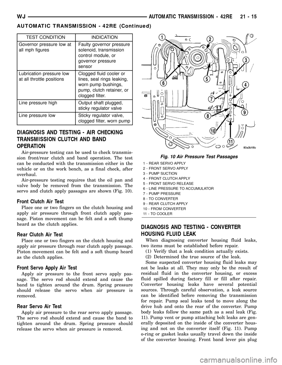
DIAGNOSIS AND TESTING - AIR CHECKING
TRANSMISSION CLUTCH AND BAND
OPERATION
Air-pressure testing can be used to check transmis-
sion front/rear clutch and band operation. The test
can be conducted with the transmission either in the
vehicle or on the work bench, as a final check, after
overhaul.
Air-pressure testing requires that the oil pan and
valve body be removed from the transmission. The
servo and clutch apply passages are shown (Fig. 10).
Front Clutch Air Test
Place one or two fingers on the clutch housing and
apply air pressure through front clutch apply pas-
sage. Piston movement can be felt and a soft thump
heard as the clutch applies.
Rear Clutch Air Test
Place one or two fingers on the clutch housing and
apply air pressure through rear clutch apply passage.
Piston movement can be felt and a soft thump heard
as the clutch applies.
Front Servo Apply Air Test
Apply air pressure to the front servo apply pas-
sage. The servo rod should extend and cause the
band to tighten around the drum. Spring pressure
should release the servo when air pressure is
removed.
Rear Servo Air Test
Apply air pressure to the rear servo apply passage.
The servo rod should extend and cause the band to
tighten around the drum. Spring pressure should
release the servo when air pressure is removed.
DIAGNOSIS AND TESTING - CONVERTER
HOUSING FLUID LEAK
When diagnosing converter housing fluid leaks,
two items must be established before repair.
(1) Verify that a leak condition actually exists.
(2) Determined the true source of the leak.
Some suspected converter housing fluid leaks may
not be leaks at all. They may only be the result of
residual fluid in the converter housing, or excess
fluid spilled during factory fill or fill after repair.
Converter housing leaks have several potential
sources. Through careful observation, a leak source
can be identified before removing the transmission
for repair. Pump seal leaks tend to move along the
drive hub and onto the rear of the converter. Pump
body leaks follow the same path as a seal leak (Fig.
11). Pump vent or pump attaching bolt leaks are gen-
erally deposited on the inside of the converter hous-
ing and not on the converter itself (Fig. 11). Pump
o-ring or gasket leaks usually travel down the inside
of the converter housing. Front band lever pin plug
Fig. 10 Air Pressure Test Passages
1 - REAR SERVO APPLY
2 - FRONT SERVO APPLY
3 - PUMP SUCTION
4 - FRONT CLUTCH APPLY
5 - FRONT SERVO RELEASE
6 - LINE PRESSURE TO ACCUMULATOR
7 - PUMP PRESSURE
8 - TO CONVERTER
9 - REAR CLUTCH APPLY
10 - FROM CONVERTER
11 - TO COOLER
WJAUTOMATIC TRANSMISSION - 42RE 21 - 15
AUTOMATIC TRANSMISSION - 42RE (Continued)
Page 1537 of 2199

CONDITION POSSIBLE CAUSES CORRECTION
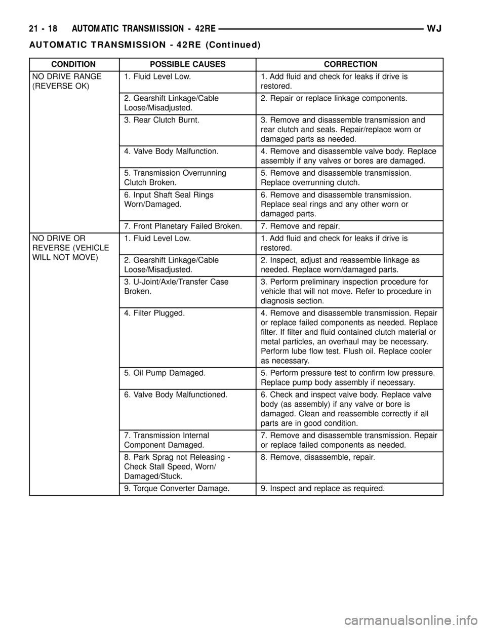
NO DRIVE RANGE
(REVERSE OK)1. Fluid Level Low. 1. Add fluid and check for leaks if drive is
restored.
2. Gearshift Linkage/Cable
Loose/Misadjusted.2. Repair or replace linkage components.
3. Rear Clutch Burnt. 3. Remove and disassemble transmission and
rear clutch and seals. Repair/replace worn or
damaged parts as needed.
4. Valve Body Malfunction. 4. Remove and disassemble valve body. Replace
assembly if any valves or bores are damaged.
5. Transmission Overrunning
Clutch Broken.5. Remove and disassemble transmission.
Replace overrunning clutch.
6. Input Shaft Seal Rings
Worn/Damaged.6. Remove and disassemble transmission.
Replace seal rings and any other worn or
damaged parts.
7. Front Planetary Failed Broken. 7. Remove and repair.
NO DRIVE OR
REVERSE (VEHICLE
WILL NOT MOVE)1. Fluid Level Low. 1. Add fluid and check for leaks if drive is
restored.
2. Gearshift Linkage/Cable
Loose/Misadjusted.2. Inspect, adjust and reassemble linkage as
needed. Replace worn/damaged parts.
3. U-Joint/Axle/Transfer Case
Broken.3. Perform preliminary inspection procedure for
vehicle that will not move. Refer to procedure in
diagnosis section.
4. Filter Plugged. 4. Remove and disassemble transmission. Repair
or replace failed components as needed. Replace
filter. If filter and fluid contained clutch material or
metal particles, an overhaul may be necessary.
Perform lube flow test. Flush oil. Replace cooler
as necessary.
5. Oil Pump Damaged. 5. Perform pressure test to confirm low pressure.
Replace pump body assembly if necessary.
6. Valve Body Malfunctioned. 6. Check and inspect valve body. Replace valve
body (as assembly) if any valve or bore is
damaged. Clean and reassemble correctly if all
parts are in good condition.
7. Transmission Internal
Component Damaged.7. Remove and disassemble transmission. Repair
or replace failed components as needed.
8. Park Sprag not Releasing -
Check Stall Speed, Worn/
Damaged/Stuck.8. Remove, disassemble, repair.
9. Torque Converter Damage. 9. Inspect and replace as required.
21 - 18 AUTOMATIC TRANSMISSION - 42REWJ
AUTOMATIC TRANSMISSION - 42RE (Continued)
Page 1541 of 2199

CONDITION POSSIBLE CAUSES CORRECTION
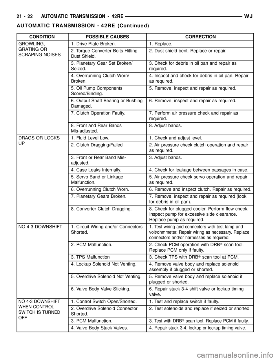
GROWLING,
GRATING OR
SCRAPING NOISES1. Drive Plate Broken. 1. Replace.
2. Torque Converter Bolts Hitting
Dust Shield.2. Dust shield bent. Replace or repair.
3. Planetary Gear Set Broken/
Seized.3. Check for debris in oil pan and repair as
required.
4. Overrunning Clutch Worn/
Broken.4. Inspect and check for debris in oil pan. Repair
as required.
5. Oil Pump Components
Scored/Binding.5. Remove, inspect and repair as required.
6. Output Shaft Bearing or Bushing
Damaged.6. Remove, inspect and repair as required.
7. Clutch Operation Faulty. 7. Perform air pressure check and repair as
required.
8. Front and Rear Bands
Mis-adjusted.8. Adjust bands.
DRAGS OR LOCKS
UP1. Fluid Level Low. 1. Check and adjust level.
2. Clutch Dragging/Failed 2. Air pressure check clutch operation and repair
as required.
3. Front or Rear Band Mis-
adjusted.3. Adjust bands.
4. Case Leaks Internally. 4. Check for leakage between passages in case.
5. Servo Band or Linkage
Malfunction.5. Air pressure check servo operation and repair
as required.
6. Overrunning Clutch Worn. 6. Remove and inspect clutch. Repair as required.
7. Planetary Gears Broken. 7. Remove, inspect and repair as required (look
for debris in oil pan).
8. Converter Clutch Dragging. 8. Check for plugged cooler. Perform flow check.
Inspect pump for excessive side clearance.
Replace pump as required.
NO 4-3 DOWNSHIFT 1. Circuit Wiring and/or Connectors
Shorted.1.
Test wiring and connectors with test lamp and
volt/ohmmeter. Repair wiring as necessary. Replace
connectors and/or harnesses as required.
2. PCM Malfunction. 2. Check PCM operation with DRBTscan tool.
Replace PCM only if faulty.
3. TPS Malfunction 3. Check TPS with DRBTscan tool at PCM.
4. Lockup Solenoid Not Venting. 4. Remove valve body and replace solenoid
assembly if plugged or shorted.
5. Overdrive Solenoid Not Venting. 5. Remove valve body and replace solenoid if
plugged or shorted.
6. Valve Body Valve Sticking. 6. Repair stuck 3-4 shift valve or lockup timing
valve.
NO 4-3 DOWNSHIFT
WHEN CONTROL
SWITCH IS TURNED
OFF1. Control Switch Open/Shorted. 1. Test and replace switch if faulty.
2. Overdrive Solenoid Connector
Shorted.2. Test solenoids and replace if seized or shorted.
3. PCM Malfunction. 3.
Test with DRBTscan tool. Replace PCM if faulty.
4. Valve Body Stuck Valves. 4.Repair stuck 3-4, lockup or lockup timing valve.
21 - 22 AUTOMATIC TRANSMISSION - 42REWJ
AUTOMATIC TRANSMISSION - 42RE (Continued)
Page 1545 of 2199

CONDITION POSSIBLE CAUSES CORRECTION
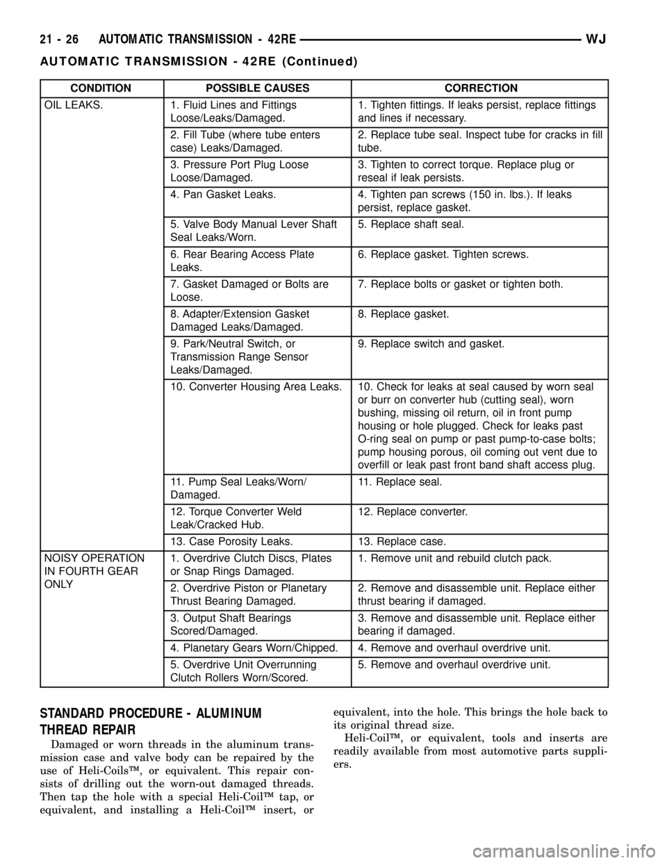
OIL LEAKS. 1. Fluid Lines and Fittings
Loose/Leaks/Damaged.1. Tighten fittings. If leaks persist, replace fittings
and lines if necessary.
2. Fill Tube (where tube enters
case) Leaks/Damaged.2. Replace tube seal. Inspect tube for cracks in fill
tube.
3. Pressure Port Plug Loose
Loose/Damaged.3. Tighten to correct torque. Replace plug or
reseal if leak persists.
4. Pan Gasket Leaks. 4. Tighten pan screws (150 in. lbs.). If leaks
persist, replace gasket.
5. Valve Body Manual Lever Shaft
Seal Leaks/Worn.5. Replace shaft seal.
6. Rear Bearing Access Plate
Leaks.6. Replace gasket. Tighten screws.
7. Gasket Damaged or Bolts are
Loose.7. Replace bolts or gasket or tighten both.
8. Adapter/Extension Gasket
Damaged Leaks/Damaged.8. Replace gasket.
9. Park/Neutral Switch, or
Transmission Range Sensor
Leaks/Damaged.9. Replace switch and gasket.
10. Converter Housing Area Leaks. 10. Check for leaks at seal caused by worn seal
or burr on converter hub (cutting seal), worn
bushing, missing oil return, oil in front pump
housing or hole plugged. Check for leaks past
O-ring seal on pump or past pump-to-case bolts;
pump housing porous, oil coming out vent due to
overfill or leak past front band shaft access plug.
11. Pump Seal Leaks/Worn/
Damaged.11. Replace seal.
12. Torque Converter Weld
Leak/Cracked Hub.12. Replace converter.
13. Case Porosity Leaks. 13. Replace case.
NOISY OPERATION
IN FOURTH GEAR
ONLY1. Overdrive Clutch Discs, Plates
or Snap Rings Damaged.1. Remove unit and rebuild clutch pack.
2. Overdrive Piston or Planetary
Thrust Bearing Damaged.2. Remove and disassemble unit. Replace either
thrust bearing if damaged.
3. Output Shaft Bearings
Scored/Damaged.3. Remove and disassemble unit. Replace either
bearing if damaged.
4. Planetary Gears Worn/Chipped. 4. Remove and overhaul overdrive unit.
5. Overdrive Unit Overrunning
Clutch Rollers Worn/Scored.5. Remove and overhaul overdrive unit.
STANDARD PROCEDURE - ALUMINUM
THREAD REPAIR
Damaged or worn threads in the aluminum trans-
mission case and valve body can be repaired by the
use of Heli-CoilsŸ, or equivalent. This repair con-
sists of drilling out the worn-out damaged threads.
Then tap the hole with a special Heli-CoilŸ tap, or
equivalent, and installing a Heli-CoilŸ insert, orequivalent, into the hole. This brings the hole back to
its original thread size.
Heli-CoilŸ, or equivalent, tools and inserts are
readily available from most automotive parts suppli-
ers.
21 - 26 AUTOMATIC TRANSMISSION - 42REWJ
AUTOMATIC TRANSMISSION - 42RE (Continued)