2002 JEEP GRAND CHEROKEE Front drive shaft
[x] Cancel search: Front drive shaftPage 1358 of 2199

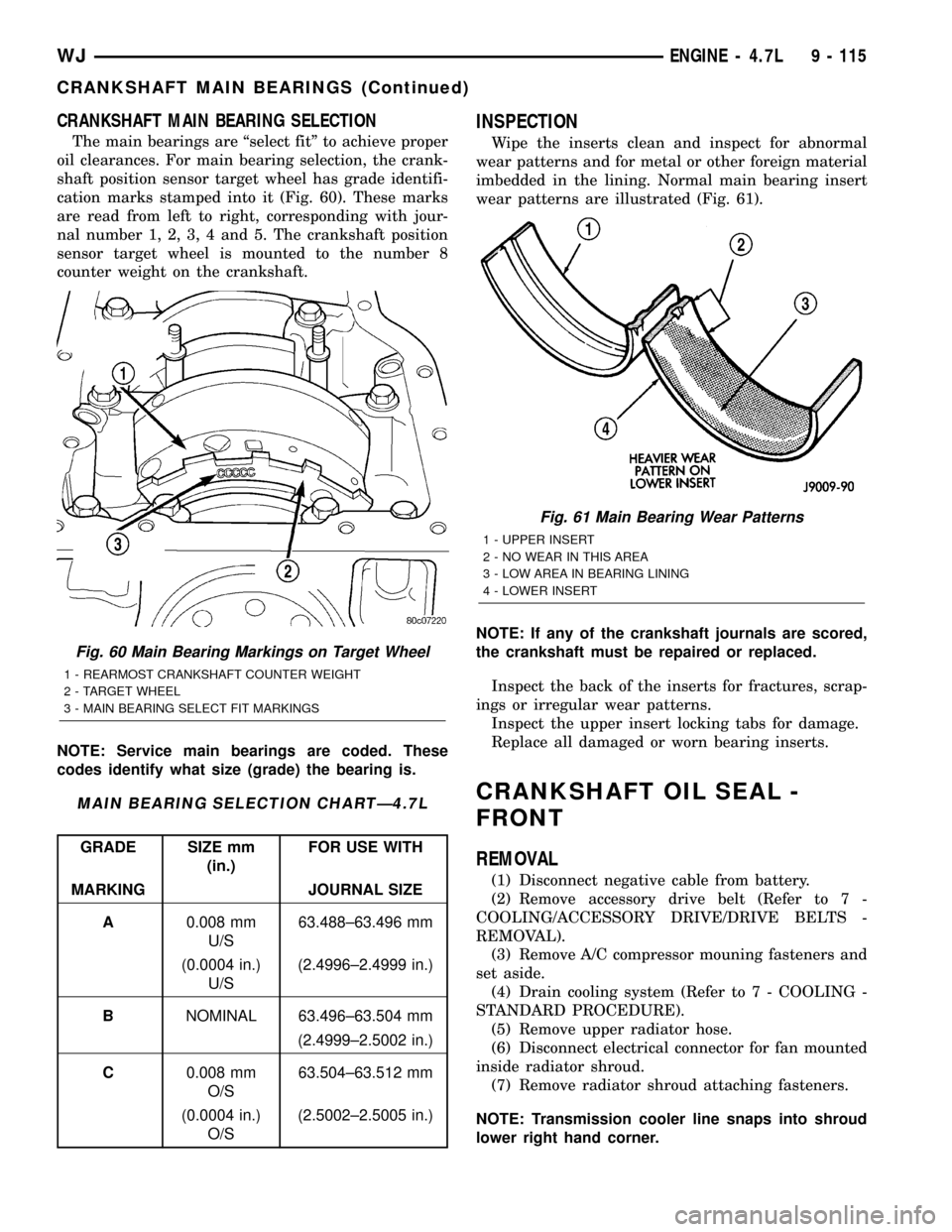
CRANKSHAFT MAIN BEARING SELECTION
The main bearings are ªselect fitº to achieve proper
oil clearances. For main bearing selection, the crank-
shaft position sensor target wheel has grade identifi-
cation marks stamped into it (Fig. 60). These marks
are read from left to right, corresponding with jour-
nal number 1, 2, 3, 4 and 5. The crankshaft position
sensor target wheel is mounted to the number 8
counter weight on the crankshaft.
NOTE: Service main bearings are coded. These
codes identify what size (grade) the bearing is.
MAIN BEARING SELECTION CHARTÐ4.7L
GRADE SIZE mm
(in.)FOR USE WITH
MARKING JOURNAL SIZE
A0.008 mm
U/S63.488±63.496 mm
(0.0004 in.)
U/S(2.4996±2.4999 in.)
BNOMINAL 63.496±63.504 mm
(2.4999±2.5002 in.)
C0.008 mm
O/S63.504±63.512 mm
(0.0004 in.)
O/S(2.5002±2.5005 in.)
INSPECTION
Wipe the inserts clean and inspect for abnormal
wear patterns and for metal or other foreign material
imbedded in the lining. Normal main bearing insert
wear patterns are illustrated (Fig. 61).
NOTE: If any of the crankshaft journals are scored,
the crankshaft must be repaired or replaced.
Inspect the back of the inserts for fractures, scrap-
ings or irregular wear patterns.
Inspect the upper insert locking tabs for damage.
Replace all damaged or worn bearing inserts.
CRANKSHAFT OIL SEAL -
FRONT
REMOVAL
(1) Disconnect negative cable from battery.
(2) Remove accessory drive belt (Refer to 7 -
COOLING/ACCESSORY DRIVE/DRIVE BELTS -
REMOVAL).
(3) Remove A/C compressor mouning fasteners and
set aside.
(4) Drain cooling system (Refer to 7 - COOLING -
STANDARD PROCEDURE).
(5) Remove upper radiator hose.
(6) Disconnect electrical connector for fan mounted
inside radiator shroud.
(7) Remove radiator shroud attaching fasteners.
NOTE: Transmission cooler line snaps into shroud
lower right hand corner.
Fig. 60 Main Bearing Markings on Target Wheel
1 - REARMOST CRANKSHAFT COUNTER WEIGHT
2 - TARGET WHEEL
3 - MAIN BEARING SELECT FIT MARKINGS
Fig. 61 Main Bearing Wear Patterns
1 - UPPER INSERT
2 - NO WEAR IN THIS AREA
3 - LOW AREA IN BEARING LINING
4 - LOWER INSERT
WJENGINE - 4.7L 9 - 115
CRANKSHAFT MAIN BEARINGS (Continued)
Page 1359 of 2199

(8) Remove radiator cooling fan and shroud (Refer
to 7 - COOLING/ENGINE/RADIATOR FAN -
REMOVAL).
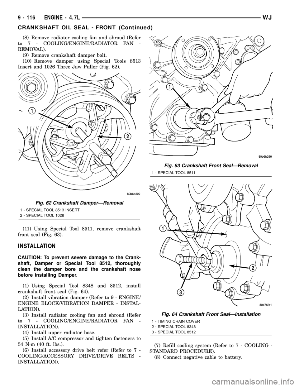
(9) Remove crankshaft damper bolt.
(10) Remove damper using Special Tools 8513
Insert and 1026 Three Jaw Puller (Fig. 62).
(11) Using Special Tool 8511, remove crankshaft
front seal (Fig. 63).
INSTALLATION
CAUTION: To prevent severe damage to the Crank-
shaft, Damper or Special Tool 8512, thoroughly
clean the damper bore and the crankshaft nose
before installing Damper.
(1) Using Special Tool 8348 and 8512, install
crankshaft front seal (Fig. 64).
(2) Install vibration damper (Refer to 9 - ENGINE/
ENGINE BLOCK/VIBRATION DAMPER - INSTAL-
LATION).
(3) Install radiator cooling fan and shroud (Refer
to 7 - COOLING/ENGINE/RADIATOR FAN -
INSTALLATION).
(4) Install upper radiator hose.
(5) Install A/C compressor and tighten fasteners to
54 N´m (40 ft. lbs.).
(6) Install accessory drive belt refer (Refer to 7 -
COOLING/ACCESSORY DRIVE/DRIVE BELTS -
INSTALLATION).(7) Refill cooling system (Refer to 7 - COOLING -
STANDARD PROCEDURE).
(8) Connect negative cable to battery.
Fig. 62 Crankshaft DamperÐRemoval
1 - SPECIAL TOOL 8513 INSERT
2 - SPECIAL TOOL 1026
Fig. 63 Crankshaft Front SealÐRemoval
1 - SPECIAL TOOL 8511
Fig. 64 Crankshaft Front SealÐInstallation
1 - TIMING CHAIN COVER
2 - SPECIAL TOOL 8348
3 - SPECIAL TOOL 8512
9 - 116 ENGINE - 4.7LWJ
CRANKSHAFT OIL SEAL - FRONT (Continued)
Page 1385 of 2199

NOTE: The blue link plates on the chains and the
dots on the camshaft drive sprockets may not line
up during the timing verification procedure. The
blue link plates are lined up with the sprocket dots
only when re-timing the complete timing drive.
Once the timing drive is rotated blue link-to-dot
alignment is no longer valid.
Engine base timing can be verified by the following
procedure:
(1) Remove the cylinder head covers (Refer to 9 -
ENGINE/CYLINDER HEAD/CYLINDER HEAD
COVER(S) - REMOVAL).
(2) Using a mirror, locate the TDC arrow on the
front cover (Fig. 110). Rotate the crankshaft until the
mark on the crankshaft damper is aligned with the
TDC arrow on the front cover. The engine is now at
TDC.(3) Note the location of the V8 mark stamped into
the camshaft drive gears (Fig. 111). If the V8 mark
on each camshaft drive gear is at the twelve o'clock
position, the engine is at TDC (cylinder #1) on the
exhaust stroke. If the V8 mark on each gear is at the
six o'clock position, the engine is at TDC (cylinder
#1) on the compression stroke.
(4) If both of the camshaft drive gears are off in
the same or opposite directions, the primary chain or
both secondary chains are at fault. Refer to Timing
Chain and Sprockets procedure in this section.
(5) If only one of the camshaft drive gears is off
and the other is correct, the problem is confined to
one secondary chain. Refer to Single camshaft tim-
ing, in this procedure.
(6) If both camshaft drive gear V8 marks are at
the twelve o'clock or the six o' clock position the
engine base timing is correct. Reinstall the cylinder
head covers.
Fig. 109 Timing Drive System
1 - RIGHT CAMSHAFT SPROCKET AND SECONDARY CHAIN
2 - SECONDARY TIMING CHAIN TENSIONER (LEFT AND RIGHT
SIDE NOT COMMON)
3 - SECONDARY TENSIONER ARM
4 - LEFT CAMSHAFT SPROCKET AND SECONDARY CHAIN
5 - CHAIN GUIDE
6 - TWO PLATED LINKS ON RIGHT CAMSHAFT CHAIN7 - PRIMARY CHAIN
8 - IDLER SPROCKET
9 - CRANKSHAFT SPROCKET
10 - PRIMARY CHAIN TENSIONER
11 - TWO PLATED LINKS ON LEFT CAMSHAFT CHAIN
12 - SECONDARY TENSIONER ARM
9 - 142 ENGINE - 4.7LWJ
VALVE TIMING (Continued)
Page 1389 of 2199

TIMING BELT / CHAIN
COVER(S)
REMOVAL
(1) Disconnect the battery negative cable.
(2) Drain cooling system (Refer to 7 - COOLING -
STANDARD PROCEDURE).
(3) Disconnect both heater hoses at timing cover.
(4) Disconnect lower radiator hose at engine.
(5) Remove crankshaft damper (Refer to 9 -
ENGINE/ENGINE BLOCK/VIBRATION DAMPER -
REMOVAL).
(6) Remove accessory drive belt tensioner assembly
(Fig. 117).
(7) Remove the generator and A/C compressor.
(8) Remove cover and gasket (Fig. 118).
INSTALLATION
(1) Clean timing chain cover and block surface.
Inspect cover gasket and replace as necessary.
(2) Install cover and gasket. Tighten fasteners in
sequence as shown in (Fig. 119) to 54 N´m (40 ft.
lbs.).
(3) Install the A/C compressor and generator.(4) Install crankshaft damper (Refer to 9 -
ENGINE/ENGINE BLOCK/VIBRATION DAMPER -
INSTALLATION).
(5) Install accessory drive belt tensioner assembly.
Tighten fastener to 54 N´m (40 ft. lbs.).
(6) Install lower radiator hose.
(7) Install both heater hoses.
(8) Fill cooling system (Refer to 7 - COOLING -
STANDARD PROCEDURE).
(9) Connect the battery negative cable.
Fig. 117 Accessory Drive Belt Tensioner
1 - TENSIONER ASSEMBLY
2 - FASTENER TENSIONER TO FRONT COVER
Fig. 118 Timing Chain Cover Fasteners
Fig. 119 Timing Chain Cover Fasteners
9 - 146 ENGINE - 4.7LWJ
Page 1519 of 2199

INSTALLATION
NOTE: The pulley is marked front for installation.
CAUTION: On vehicles equipped with the 4.0L or
4.7L, Do not reuse the old power steering pump
pulley it is not intended for reuse. A new pulley
must be installed if removed.
(1) Replace pulley if bent, cracked, or loose.
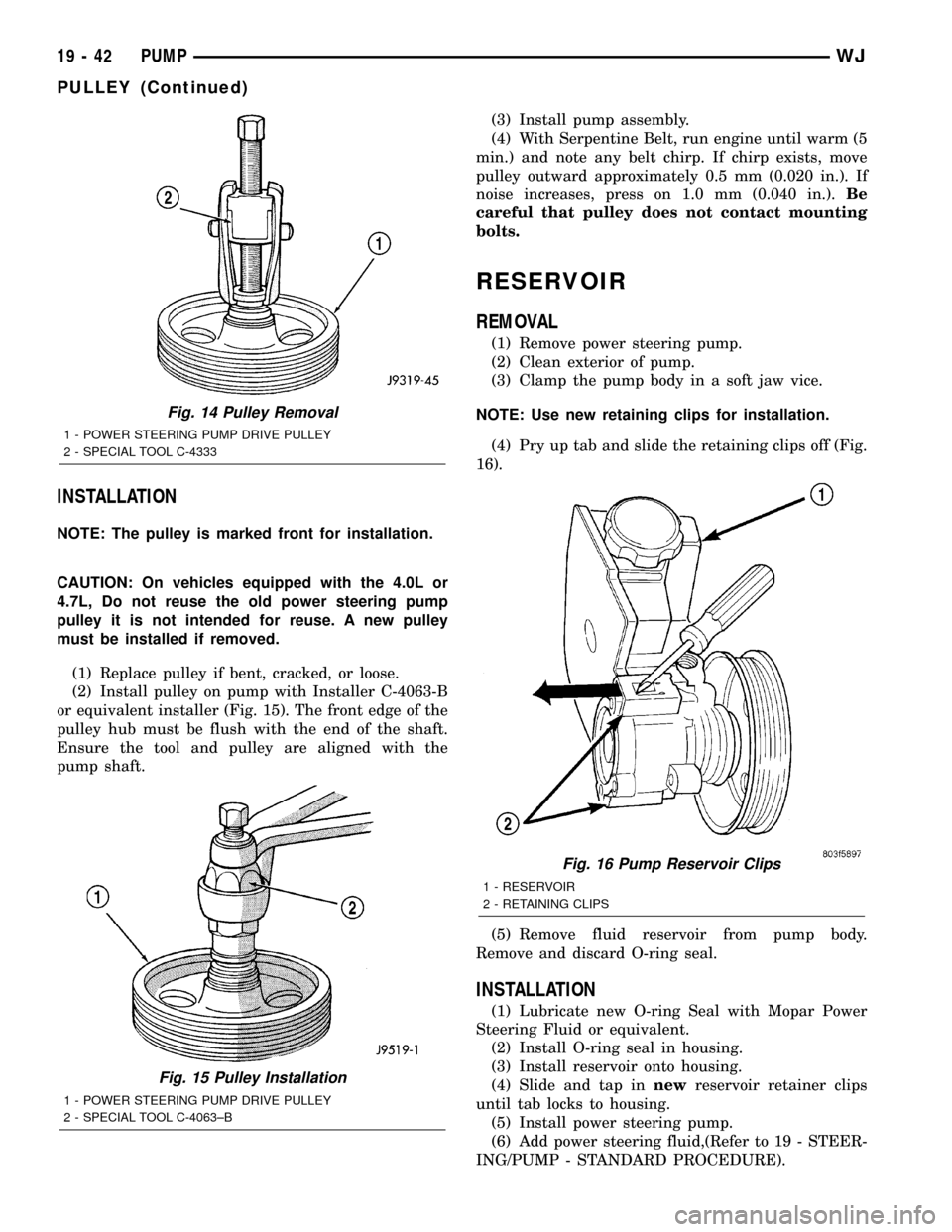
(2) Install pulley on pump with Installer C-4063-B
or equivalent installer (Fig. 15). The front edge of the
pulley hub must be flush with the end of the shaft.
Ensure the tool and pulley are aligned with the
pump shaft.(3) Install pump assembly.
(4) With Serpentine Belt, run engine until warm (5
min.) and note any belt chirp. If chirp exists, move
pulley outward approximately 0.5 mm (0.020 in.). If
noise increases, press on 1.0 mm (0.040 in.).Be
careful that pulley does not contact mounting
bolts.
RESERVOIR
REMOVAL
(1) Remove power steering pump.
(2) Clean exterior of pump.
(3) Clamp the pump body in a soft jaw vice.
NOTE: Use new retaining clips for installation.
(4) Pry up tab and slide the retaining clips off (Fig.
16).
(5) Remove fluid reservoir from pump body.
Remove and discard O-ring seal.
INSTALLATION
(1) Lubricate new O-ring Seal with Mopar Power
Steering Fluid or equivalent.
(2) Install O-ring seal in housing.
(3) Install reservoir onto housing.
(4) Slide and tap innewreservoir retainer clips
until tab locks to housing.
(5) Install power steering pump.
(6) Add power steering fluid,(Refer to 19 - STEER-
ING/PUMP - STANDARD PROCEDURE).
Fig. 14 Pulley Removal
1 - POWER STEERING PUMP DRIVE PULLEY
2 - SPECIAL TOOL C-4333
Fig. 15 Pulley Installation
1 - POWER STEERING PUMP DRIVE PULLEY
2 - SPECIAL TOOL C-4063±B
Fig. 16 Pump Reservoir Clips
1 - RESERVOIR
2 - RETAINING CLIPS
19 - 42 PUMPWJ
PULLEY (Continued)
Page 1521 of 2199

STANDARD PROCEDURE - FLUID AND
FILTER REPLACEMENT................71
STANDARD PROCEDURE - TRANSMISSION
FILL................................72
FRONT CLUTCH
DESCRIPTION.........................73
OPERATION...........................74
DISASSEMBLY.........................74
INSPECTION..........................74
ASSEMBLY............................74
FRONT SERVO
DESCRIPTION.........................77
OPERATION...........................77
DISASSEMBLY.........................77
CLEANING............................77
INSPECTION..........................77
ASSEMBLY............................77
GEARSHIFT CABLE
DIAGNOSIS AND TESTING - GEARSHIFT
CABLE..............................78
REMOVAL.............................78
INSTALLATION.........................79
ADJUSTMENTS - GEARSHIFT CABLE.......79
OIL PUMP
DESCRIPTION.........................80
OPERATION...........................80
STANDARD PROCEDURE - OIL PUMP
VOLUME CHECK......................81
DISASSEMBLY.........................81
CLEANING............................83
INSPECTION..........................83
ASSEMBLY............................83
OUTPUT SHAFT FRONT BEARING
REMOVAL.............................85
INSTALLATION.........................85
OUTPUT SHAFT REAR BEARING
REMOVAL.............................85
INSTALLATION.........................85
OVERDRIVE CLUTCH
DESCRIPTION.........................86
OPERATION...........................86
OVERDRIVE OFF SWITCH
DESCRIPTION.........................86
OPERATION...........................86
DIAGNOSIS AND TESTING - OVERDRIVE
ELECTRICAL CONTROLS...............87
OVERDRIVE UNIT
REMOVAL.............................87
DISASSEMBLY.........................88
CLEANING............................95
INSPECTION..........................95
ASSEMBLY............................95
INSTALLATION........................104
OVERRUNNING CLUTCH CAM/OVERDRIVE
PISTON RETAINER
DESCRIPTION........................105
OPERATION..........................105DISASSEMBLY........................106
CLEANING...........................106
INSPECTION.........................106
ASSEMBLY...........................106
PARK LOCK CABLE
REMOVAL............................108
INSTALLATION........................108
PARK/NEUTRAL POSITION SWITCH
DIAGNOSIS AND TESTING - PARK/NEUTRAL
POSITION SWITCH...................109
REMOVAL............................109
INSTALLATION........................109
PISTONS
DESCRIPTION........................110
OPERATION..........................110
PLANETARY GEARTRAIN/OUTPUT SHAFT
DESCRIPTION........................112
OPERATION..........................112
DISASSEMBLY........................112
INSPECTION..........................113
ASSEMBLY...........................113
REAR CLUTCH
DESCRIPTION........................118
OPERATION..........................118
DISASSEMBLY........................119
CLEANING...........................119
INSPECTION.........................120
ASSEMBLY...........................120
REAR SERVO
DESCRIPTION........................122
OPERATION..........................122
DISASSEMBLY........................122
CLEANING...........................122
ASSEMBLY...........................123
SHIFT MECHANISM
DESCRIPTION........................123
OPERATION..........................123
REMOVAL............................123
INSTALLATION........................125
SOLENOID
DESCRIPTION........................125
OPERATION..........................126
SPEED SENSOR
DESCRIPTION........................126
OPERATION..........................126
THROTTLE VALVE CABLE
DESCRIPTION........................126
ADJUSTMENTS - TRANSMISSION THROTTLE
VALVE CABLE.......................126
TORQUE CONVERTER
DESCRIPTION........................128
OPERATION..........................132
REMOVAL............................133
INSTALLATION........................133
TORQUE CONVERTER DRAINBACK VALVE
DESCRIPTION........................134
OPERATION..........................134
21 - 2 AUTOMATIC TRANSMISSION - 42REWJ
Page 1522 of 2199

STANDARD PROCEDURE - TORQUE
CONVERTER DRAINBACK VALVE........134
TRANSMISSION TEMPERATURE SENSOR
DESCRIPTION........................134
OPERATION..........................134
VALVE BODY
DESCRIPTION........................135
OPERATION..........................139REMOVAL............................154
DISASSEMBLY........................155
CLEANING...........................165
INSPECTION.........................166
ASSEMBLY...........................167
INSTALLATION........................175
ADJUSTMENTS - VALVE BODY...........175
AUTOMATIC TRANSMISSION -
42RE
DESCRIPTION
The 42RE is a four speed fully automatic transmis-
sion (Fig. 1) with an electronic governor. The 42RE is
equipped with a lock-up clutch in the torque con-
verter. First through third gear ranges are provided
by the clutches, bands, overrunning clutch, and plan-
etary gear sets in the transmission. Fourth gear
range is provided by the overdrive unit that contains
an overdrive clutch, direct clutch, planetary gear set,
and overrunning clutch.The transmission contains a front, rear, and direct
clutch which function as the input driving compo-
nents. It also contains the kickdown (front) and the
low/reverse (rear) bands which, along with the over-
running clutch and overdrive clutch, serve as the
holding components. The driving and holding compo-
nents combine to select the necessary planetary gear
components, in the front, rear, or overdrive planetary
gear set, transfer the engine power from the input
shaft through to the output shaft.
The valve body is mounted to the lower side of the
transmission and contains the valves to control pres-
sure regulation, fluid flow control, and clutch/band
application. The oil pump is mounted at the front of
the transmission and is driven by the torque con-
verter hub. The pump supplies the oil pressure nec-
essary for clutch/band actuation and transmission
lubrication.
WJAUTOMATIC TRANSMISSION - 42RE 21 - 3
Page 1524 of 2199

IDENTIFICATION
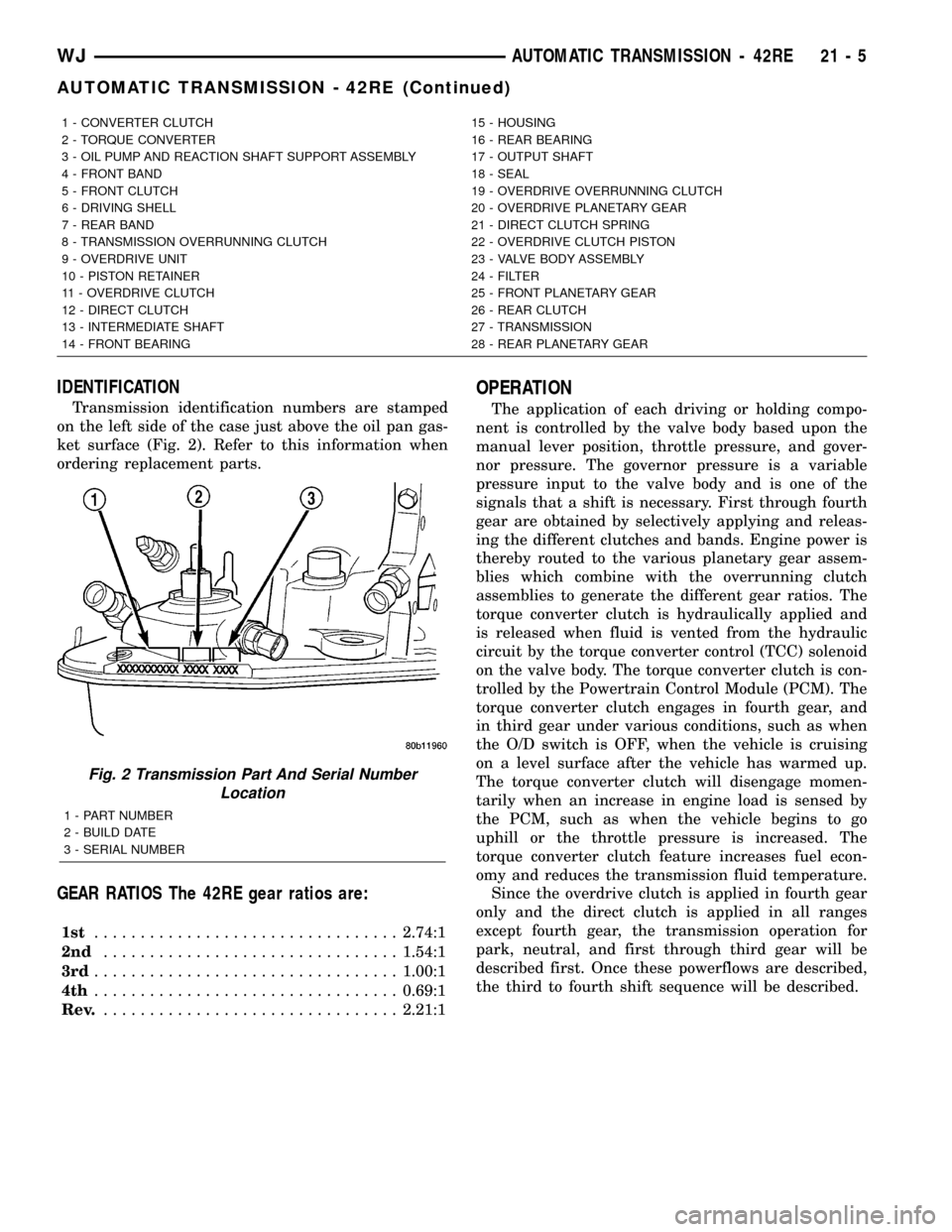
Transmission identification numbers are stamped
on the left side of the case just above the oil pan gas-
ket surface (Fig. 2). Refer to this information when
ordering replacement parts.
GEAR RATIOS The 42RE gear ratios are:
1st.................................2.74:1
2nd................................1.54:1
3rd.................................1.00:1
4th.................................0.69:1
Rev.................................2.21:1
OPERATION
The application of each driving or holding compo-
nent is controlled by the valve body based upon the
manual lever position, throttle pressure, and gover-
nor pressure. The governor pressure is a variable
pressure input to the valve body and is one of the
signals that a shift is necessary. First through fourth
gear are obtained by selectively applying and releas-
ing the different clutches and bands. Engine power is
thereby routed to the various planetary gear assem-
blies which combine with the overrunning clutch
assemblies to generate the different gear ratios. The
torque converter clutch is hydraulically applied and
is released when fluid is vented from the hydraulic
circuit by the torque converter control (TCC) solenoid
on the valve body. The torque converter clutch is con-
trolled by the Powertrain Control Module (PCM). The
torque converter clutch engages in fourth gear, and
in third gear under various conditions, such as when
the O/D switch is OFF, when the vehicle is cruising
on a level surface after the vehicle has warmed up.
The torque converter clutch will disengage momen-
tarily when an increase in engine load is sensed by
the PCM, such as when the vehicle begins to go
uphill or the throttle pressure is increased. The
torque converter clutch feature increases fuel econ-
omy and reduces the transmission fluid temperature.
Since the overdrive clutch is applied in fourth gear
only and the direct clutch is applied in all ranges
except fourth gear, the transmission operation for
park, neutral, and first through third gear will be
described first. Once these powerflows are described,
the third to fourth shift sequence will be described.
1 - CONVERTER CLUTCH 15 - HOUSING
2 - TORQUE CONVERTER 16 - REAR BEARING
3 - OIL PUMP AND REACTION SHAFT SUPPORT ASSEMBLY 17 - OUTPUT SHAFT
4 - FRONT BAND 18 - SEAL
5 - FRONT CLUTCH 19 - OVERDRIVE OVERRUNNING CLUTCH
6 - DRIVING SHELL 20 - OVERDRIVE PLANETARY GEAR
7 - REAR BAND 21 - DIRECT CLUTCH SPRING
8 - TRANSMISSION OVERRUNNING CLUTCH 22 - OVERDRIVE CLUTCH PISTON
9 - OVERDRIVE UNIT 23 - VALVE BODY ASSEMBLY
10 - PISTON RETAINER 24 - FILTER
11 - OVERDRIVE CLUTCH 25 - FRONT PLANETARY GEAR
12 - DIRECT CLUTCH 26 - REAR CLUTCH
13 - INTERMEDIATE SHAFT 27 - TRANSMISSION
14 - FRONT BEARING 28 - REAR PLANETARY GEAR
Fig. 2 Transmission Part And Serial Number
Location
1 - PART NUMBER
2 - BUILD DATE
3 - SERIAL NUMBER
WJAUTOMATIC TRANSMISSION - 42RE 21 - 5
AUTOMATIC TRANSMISSION - 42RE (Continued)