2002 JEEP GRAND CHEROKEE Rear main seal
[x] Cancel search: Rear main sealPage 1273 of 2199

ENGINE BLOCK
CLEANING
Thoroughly clean the oil pan and engine block gas-
ket surfaces.
Use compressed air to clean out:
²The galley at the oil filter adaptor hole.
²The front and rear oil galley holes.
²The feed holes for the crankshaft main bearings.
Once the block has been completely cleaned, apply
Loctite PST pipe sealant with Teflon 592 to the
threads of the front and rear oil galley plugs. Tighten
the plugs to 34 N´m (25 ft. lbs.) torque.
INSPECTION
(1) It is mandatory to use a dial bore gauge to
measure each cylinder bore diameter (Fig. 29). To
correctly select the proper size piston, a cylinder bore
gauge, capable of reading in 0.003 mm (.0001 in.)
INCREMENTS is required. If a bore gauge is not
available, do not use an inside micrometer.
(2) Measure the inside diameter of the cylinder
bore at three levels below top of bore. Start perpen-
dicular (across or at 90 degrees) to the axis of the
crankshaft and then take two additional reading.(3) Measure the cylinder bore diameter crosswise
to the cylinder block near the top of the bore. Repeat
the measurement near the middle of the bore, then
repeat the measurement near the bottom of the bore.
(4) Determine taper by subtracting the smaller
diameter from the larger diameter.
(5) Rotate measuring device 90É and repeat steps
above.
(6) Determine out-of-roundness by comparing the
difference between each measurement.
(7) If cylinder bore taper does not exceed 0.025
mm (0.001 inch) and out-of-roundness does not
exceed 0.025 mm (0.001 inch), the cylinder bore can
be honed. If the cylinder bore taper or out- of-round
condition exceeds these maximum limits, the cylinder
must be bored and then honed to accept an oversize
piston. A slight amount of taper always exists in the
cylinder bore after the engine has been in use for a
period of time.
CAMSHAFT & BEARINGS
DESCRIPTION
The camshaft is made of gray cast iron with twelve
machined lobes and four bearing journals (Fig. 30).
When the camshaft rotates the lobes actuate the tap-
pets and push rods, forcing upward on the rocker
arms which applies downward force on the valves.
Fig. 28 Valve and Valve
1 - VALVE LOCKS (3±BEAD)
2 - RETAINER
3 - VALVE STEM OIL SEAL
4 - INTAKE VALVE
5 - EXHAUST VALVE
6 - VALVE SPRINGFig. 29 Cylinder Bore Measurement
9 - 30 ENGINE - 4.0LWJ
VALVE SPRINGS (Continued)
Page 1278 of 2199

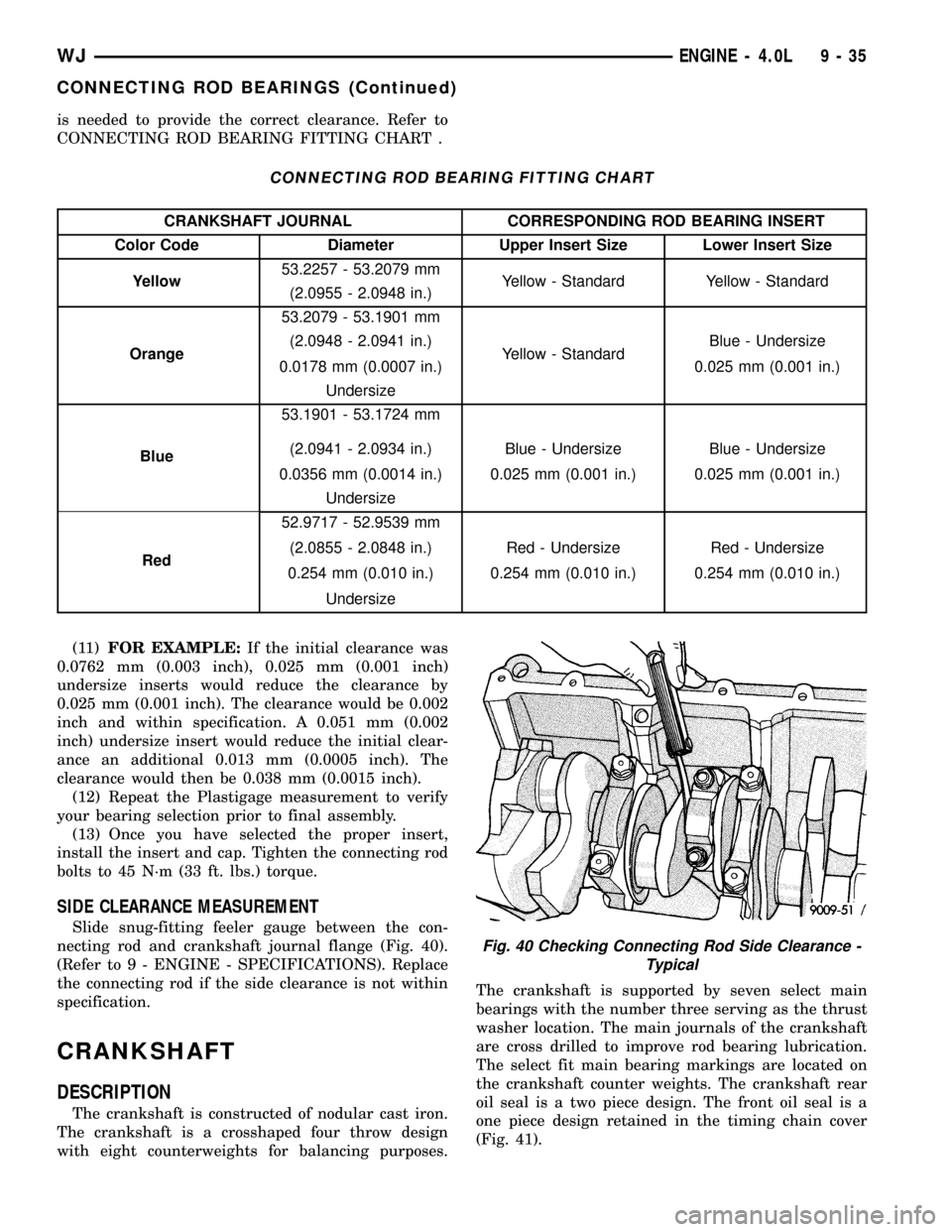
is needed to provide the correct clearance. Refer to
CONNECTING ROD BEARING FITTING CHART .
CONNECTING ROD BEARING FITTING CHART
CRANKSHAFT JOURNAL CORRESPONDING ROD BEARING INSERT
Color Code Diameter Upper Insert Size Lower Insert Size
Yellow53.2257 - 53.2079 mm
Yellow - Standard Yellow - Standard
(2.0955 - 2.0948 in.)
Orange53.2079 - 53.1901 mm
Yellow - StandardBlue - Undersize (2.0948 - 2.0941 in.)
0.0178 mm (0.0007 in.) 0.025 mm (0.001 in.)
Undersize
Blue53.1901 - 53.1724 mm
Blue - Undersize Blue - Undersize (2.0941 - 2.0934 in.)
0.0356 mm (0.0014 in.) 0.025 mm (0.001 in.) 0.025 mm (0.001 in.)
Undersize
Red52.9717 - 52.9539 mm
Red - Undersize Red - Undersize (2.0855 - 2.0848 in.)
0.254 mm (0.010 in.) 0.254 mm (0.010 in.) 0.254 mm (0.010 in.)
Undersize
(11)FOR EXAMPLE:If the initial clearance was
0.0762 mm (0.003 inch), 0.025 mm (0.001 inch)
undersize inserts would reduce the clearance by
0.025 mm (0.001 inch). The clearance would be 0.002
inch and within specification. A 0.051 mm (0.002
inch) undersize insert would reduce the initial clear-
ance an additional 0.013 mm (0.0005 inch). The
clearance would then be 0.038 mm (0.0015 inch).
(12) Repeat the Plastigage measurement to verify
your bearing selection prior to final assembly.
(13) Once you have selected the proper insert,
install the insert and cap. Tighten the connecting rod
bolts to 45 N´m (33 ft. lbs.) torque.
SIDE CLEARANCE MEASUREMENT
Slide snug-fitting feeler gauge between the con-
necting rod and crankshaft journal flange (Fig. 40).
(Refer to 9 - ENGINE - SPECIFICATIONS). Replace
the connecting rod if the side clearance is not within
specification.
CRANKSHAFT
DESCRIPTION
The crankshaft is constructed of nodular cast iron.
The crankshaft is a crosshaped four throw design
with eight counterweights for balancing purposes.The crankshaft is supported by seven select main
bearings with the number three serving as the thrust
washer location. The main journals of the crankshaft
are cross drilled to improve rod bearing lubrication.
The select fit main bearing markings are located on
the crankshaft counter weights. The crankshaft rear
oil seal is a two piece design. The front oil seal is a
one piece design retained in the timing chain cover
(Fig. 41).
Fig. 40 Checking Connecting Rod Side Clearance -
Typical
WJENGINE - 4.0L 9 - 35
CONNECTING ROD BEARINGS (Continued)
Page 1283 of 2199

INSPECTION
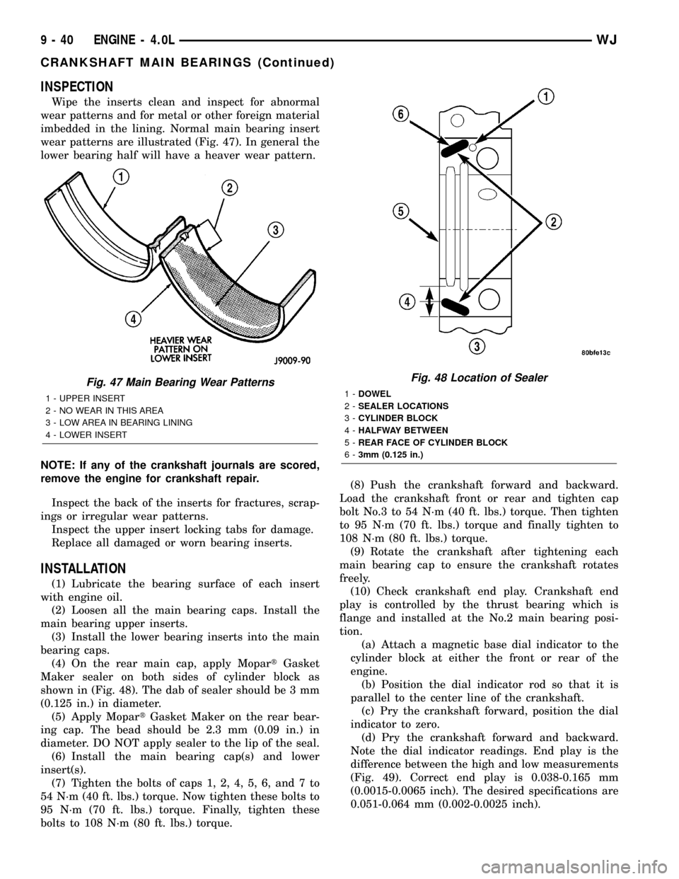
Wipe the inserts clean and inspect for abnormal
wear patterns and for metal or other foreign material
imbedded in the lining. Normal main bearing insert
wear patterns are illustrated (Fig. 47). In general the
lower bearing half will have a heaver wear pattern.
NOTE: If any of the crankshaft journals are scored,
remove the engine for crankshaft repair.
Inspect the back of the inserts for fractures, scrap-
ings or irregular wear patterns.
Inspect the upper insert locking tabs for damage.
Replace all damaged or worn bearing inserts.
INSTALLATION
(1) Lubricate the bearing surface of each insert
with engine oil.
(2) Loosen all the main bearing caps. Install the
main bearing upper inserts.
(3) Install the lower bearing inserts into the main
bearing caps.
(4) On the rear main cap, apply MopartGasket
Maker sealer on both sides of cylinder block as
shown in (Fig. 48). The dab of sealer should be 3 mm
(0.125 in.) in diameter.
(5) Apply MopartGasket Maker on the rear bear-
ing cap. The bead should be 2.3 mm (0.09 in.) in
diameter. DO NOT apply sealer to the lip of the seal.
(6) Install the main bearing cap(s) and lower
insert(s).
(7) Tighten the bolts of caps 1, 2, 4, 5, 6, and 7 to
54 N´m (40 ft. lbs.) torque. Now tighten these bolts to
95 N´m (70 ft. lbs.) torque. Finally, tighten these
bolts to 108 N´m (80 ft. lbs.) torque.(8) Push the crankshaft forward and backward.
Load the crankshaft front or rear and tighten cap
bolt No.3 to 54 N´m (40 ft. lbs.) torque. Then tighten
to 95 N´m (70 ft. lbs.) torque and finally tighten to
108 N´m (80 ft. lbs.) torque.
(9) Rotate the crankshaft after tightening each
main bearing cap to ensure the crankshaft rotates
freely.
(10) Check crankshaft end play. Crankshaft end
play is controlled by the thrust bearing which is
flange and installed at the No.2 main bearing posi-
tion.
(a) Attach a magnetic base dial indicator to the
cylinder block at either the front or rear of the
engine.
(b) Position the dial indicator rod so that it is
parallel to the center line of the crankshaft.
(c) Pry the crankshaft forward, position the dial
indicator to zero.
(d) Pry the crankshaft forward and backward.
Note the dial indicator readings. End play is the
difference between the high and low measurements
(Fig. 49). Correct end play is 0.038-0.165 mm
(0.0015-0.0065 inch). The desired specifications are
0.051-0.064 mm (0.002-0.0025 inch).
Fig. 47 Main Bearing Wear Patterns
1 - UPPER INSERT
2 - NO WEAR IN THIS AREA
3 - LOW AREA IN BEARING LINING
4 - LOWER INSERT
Fig. 48 Location of Sealer
1-DOWEL
2-SEALER LOCATIONS
3-CYLINDER BLOCK
4-HALFWAY BETWEEN
5-REAR FACE OF CYLINDER BLOCK
6-3mm (0.125 in.)
9 - 40 ENGINE - 4.0LWJ
CRANKSHAFT MAIN BEARINGS (Continued)
Page 1285 of 2199

CRANKSHAFT OIL SEAL -
REAR
REMOVAL
The crankshaft rear main bearing oil seal consists
of two half pieces of viton with a single lip that effec-
tively seals the rear of the crankshaft. Replace the
upper and lower seal halves as a unit to ensure leak-
free operation.
(1) Remove transmission inspection cover.
(2) Remove oil pan. (Refer to 9 - ENGINE/LUBRI-
CATION/OIL PAN - REMOVAL)
(3) Remove main bearing cap brace.
(4) Remove rear main bearing cap (No.7).
(5) Push upper seal out of the groove. Ensure that
the crankshaft and seal groove are not damaged.
(6) Remove lower half of the seal from the bearing
cap.
INSTALLATION
The crankshaft rear main bearing oil seal consists
of two half pieces of viton with a single lip that effec-
tively seals the rear of the crankshaft. Replace the
upper and lower seal halves as a unit to ensure leak-
free operation.
(1) Wipe the seal surface area of the crankshaft
until it is clean.
(2) Apply a thin coat of engine oil.
(3) Coat lip of the seal with engine oil.
(4) Carefully position the upper seal into the
groove in the cylinder block. The lip of the seal faces
toward the front of the engine.
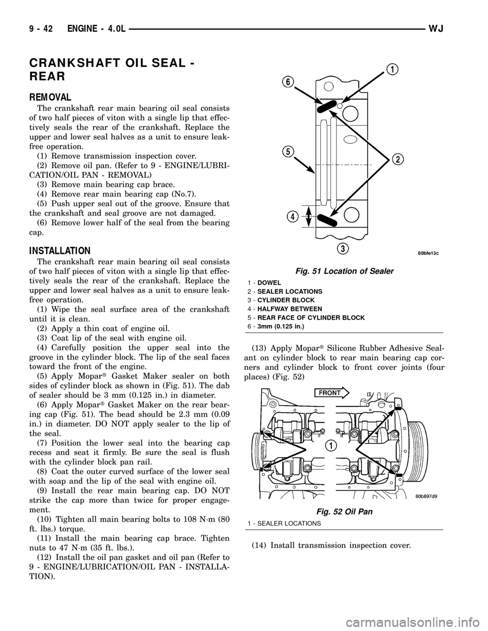
(5) Apply MopartGasket Maker sealer on both
sides of cylinder block as shown in (Fig. 51). The dab
of sealer should be 3 mm (0.125 in.) in diameter.
(6) Apply MopartGasket Maker on the rear bear-
ing cap (Fig. 51). The bead should be 2.3 mm (0.09
in.) in diameter. DO NOT apply sealer to the lip of
the seal.
(7) Position the lower seal into the bearing cap
recess and seat it firmly. Be sure the seal is flush
with the cylinder block pan rail.
(8) Coat the outer curved surface of the lower seal
with soap and the lip of the seal with engine oil.
(9) Install the rear main bearing cap. DO NOT
strike the cap more than twice for proper engage-
ment.
(10) Tighten all main bearing bolts to 108 N´m (80
ft. lbs.) torque.
(11) Install the main bearing cap brace. Tighten
nuts to 47 N´m (35 ft. lbs.).
(12) Install the oil pan gasket and oil pan (Refer to
9 - ENGINE/LUBRICATION/OIL PAN - INSTALLA-
TION).(13) Apply MopartSilicone Rubber Adhesive Seal-
ant on cylinder block to rear main bearing cap cor-
ners and cylinder block to front cover joints (four
places) (Fig. 52)
(14) Install transmission inspection cover.
Fig. 51 Location of Sealer
1-DOWEL
2-SEALER LOCATIONS
3-CYLINDER BLOCK
4-HALFWAY BETWEEN
5-REAR FACE OF CYLINDER BLOCK
6-3mm (0.125 in.)
Fig. 52 Oil Pan
1 - SEALER LOCATIONS
9 - 42 ENGINE - 4.0LWJ
Page 1294 of 2199

crankshaft is drilled internally to pass oil from the
main bearing journals (except number 4 main bear-
ing journal) to the connecting rod journals. Each con-
necting rod bearing cap has a small squirt hole, oil
passes through the squirt hole and is thrown off as
the rod rotates. This oil throwoff lubricates the cam-
shaft lobes, distributor drive gear, cylinder walls, and
piston pins.
The hydraulic valve tappets receive oil directly
from the main oil gallery. Oil is provided to the cam-
shaft bearing through galleries. The front camshaft
bearing journal passes oil through the camshaft
sprocket to the timing chain. Oil drains back to the
oil pan under the number one main bearing cap.
The oil supply for the rocker arms and bridged
pivot assemblies is provided by the hydraulic valve
tappets which pass oil through hollow push rods to a
hole in the corresponding rocker arm. Oil from the
rocker arm lubricates the valve train components,
then passes down through the push rod guide holes
in the cylinder head past the valve tappet area, and
returns to the oil pan (Fig. 73).
DIAGNOSIS AND TESTING
DIAGNOSIS AND TESTING - ENGINE OIL
PRESSURE
(1) Disconnect connector and remove oil pressure
sending unit.
(2) Install Oil Pressure Line and Gauge Tool
C-3292 or equivalent. Start engine and record pres-
sure. (Refer to 9 - ENGINE - SPECIFICATIONS) for
the correct pressures.
DIAGNOSIS AND TESTING - ENGINE OIL LEAK
Begin with a thorough visual inspection of the
engine, particularly at the area of the suspected leak.
If an oil leak source is not readily identifiable, the
following steps should be followed:
(1) Do not clean or degrease the engine at this
time because some solvents may cause rubber to
swell, temporarily stopping the leak.
(2) Add an oil soluble dye (use as recommended by
manufacturer). Start the engine and let idle for
approximately 15 minutes. Check the oil dipstick to
make sure the dye is thoroughly mixed as indicated
with a bright yellow color under a black light.
(3) Using a black light, inspect the entire engine
for fluorescent dye, particularly at the suspected area
of oil leak. If the oil leak is found and identified,
repair per service manual instructions.
(4) If dye is not observed, drive the vehicle at var-
ious speeds for approximately 24km (15 miles), and
repeat inspection.If the oil leak source is not pos-itively identified at this time, proceed with the air
leak detection test method.
Air Leak Detection Test Method
(1) Disconnect the breather cap to air cleaner hose
at the breather cap end. Cap or plug breather cap
nipple.
(2) Remove the CCV valve from the cylinder head
cover. Cap or plug the CCV valve grommet.
(3) Attach an air hose with pressure gauge and
regulator to the dipstick tube.
CAUTION: Do not subject the engine assembly to
more than 20.6 kpa (3 PSI) of test pressure.
(4) Gradually apply air pressure from 1 psi to 2.5
psi maximum while applying soapy water at the sus-
pected source. Adjust the regulator to the suitable
test pressure that provide the best bubbles which
will pinpoint the leak source. If the oil leak is
detected and identified, repair per service informa-
tion procedures.
(5) If the leakage occurs at the rear oil seal area,
INSPECTION FOR REAR SEAL AREA LEAKS .
(6) If no leaks are detected, turn off the air supply
and remove the air hose and all plugs and caps.
Install the CCV valve and breather cap hose.
(7) Clean the oil off the suspect oil leak area using
a suitable solvent. Drive the vehicle at various
speeds approximately 24 km (15 miles). Inspect the
engine for signs of an oil leak by using a black light.
INSPECTION FOR REAR SEAL AREA LEAKS
Since it is sometimes difficult to determine the
source of an oil leak in the rear seal area of the
engine, a more involved inspection is necessary. The
following steps should be followed to help pinpoint
the source of the leak.
If the leakage occurs at the crankshaft rear oil seal
area:
(1) Disconnect the battery.
(2) Raise the vehicle.
(3) Remove torque converter or clutch housing
cover and inspect rear of block for evidence of oil.
Use a black light to check for the oil leak:
(a) Circular spray pattern generally indicates
seal leakage or crankshaft damage.
(b) Where leakage tends to run straight down,
possible causes are a porous block, distributor seal,
camshaft bore cup plugs oil galley pipe plugs, oil
filter runoff, and main bearing cap to cylinder
block mating surfaces.
(4) If no leaks are detected, pressurize the crank-
case as outlined in the, Inspection (Engine oil Leaks
in general)
CAUTION: Do not exceed 20.6 kPa (3 psi).
WJENGINE - 4.0L 9 - 51
LUBRICATION (Continued)
Page 1296 of 2199

(5) If the leak is not detected, very slowly turn the
crankshaft and watch for leakage. If a leak is
detected between the crankshaft and seal while
slowly turning the crankshaft, it is possible the
crankshaft seal surface is damaged. The seal area on
the crankshaft could have minor nicks or scratches
that can be polished out with emery cloth.
CAUTION: Use extreme caution when crankshaft
polishing is necessary to remove minor nicks and
scratches. The crankshaft seal flange is especially
machined to complement the function of the rear oil
seal.
(6) For bubbles that remain steady with shaft
rotation, no further inspection can be done until dis-
assembled.
OIL
STANDARD PROCEDURE - ENGINE OIL
SERVICE
ENGINE OIL CHANGE
Change engine oil at mileage and time intervals
described in Maintenance Schedules.
Run engine until achieving normal operating tem-
perature.
(1) Position the vehicle on a level surface and turn
engine off.
(2) Hoist and support vehicle on safety stands.
(3) Remove oil fill cap.
(4) Place a suitable drain pan under crankcase
drain.
(5) Remove drain plug from crankcase and allow
oil to drain into pan. Inspect drain plug threads for
stretching or other damage. Replace drain plug if
damaged.
(6) Install drain plug in crankcase.
(7) Replace engine oil filter. (Refer to 9 - ENGINE/
LUBRICATION/OIL FILTER - REMOVAL).
(8) Lower vehicle and fill crankcase with specified
type of engine oil (Refer to LUBRICATION & MAIN-
TENANCE/FLUID TYPES - DESCRIPTION) and
amount of engine oil (Refer to LUBRICATION &
MAINTENANCE - SPECIFICATIONS).
(9) Install oil fill cap.
(10) Start engine and inspect for leaks.
(11) Stop engine and inspect oil level. Refer to
CRANKCASE OIL LEVEL INSPECTION .
USED ENGINE OIL DISPOSAL
Care should be exercised when disposing used
engine oil after it has been drained from a vehicle
engine.
CRANKCASE OIL LEVEL INSPECTION
CAUTION: Do not overfill crankcase with engine oil,
oil foaming and oil pressure loss can result.
The engine oil level indicator (Dipstick) is located
at the right rear of the 4.0L engine. Inspect engine
oil level approximately every 800 kilometers (500
miles). Unless the engine has exhibited loss of oil
pressure, run the engine for about five minutes
before checking oil level. Checking engine oil level on
a cold engine is not accurate.
To ensure proper lubrication of an engine, the
engine oil must be maintained at an acceptable level.
The acceptable levels are indicated between the ADD
and SAFE marks on the engine oil dipstick (Fig. 74).
(1) Position vehicle on level surface.
(2) With engine OFF, allow approximately ten min-
utes for oil to settle to bottom of crankcase, remove
engine oil dipstick.
(3) Wipe dipstick clean.
(4) Install dipstick and verify it is seated in the
tube.
(5) Remove dipstick, with handle held above the
tip, take oil level reading (Fig. 74).
(6) Add oil only if level is below the ADD mark on
dipstick.
OIL FILTER
REMOVAL
CAUTION: Do not use oil filter with metric threads.
The proper oil filter has SAE type 3/4 X 16 threads.
An oil filter with metric threads can result in oil
leaks and engine failure.
Fig. 74 Engine Oil DipstickÐ4.0L Engine
1 - DIPSTICK
2 - ADD
3 - SAFE
WJENGINE - 4.0L 9 - 53
LUBRICATION (Continued)
Page 1298 of 2199

(10) Place a piece of wood (2 x 2) between the jack
stand and the engine vibration damper.
(11) Remove the engine mount through bolts.
(12) Using the jack stand, raise the engine until
adequate clearance is obtained to remove the oil pan.
(13) Remove transmission oil cooling lines (if
equipped) and oxygen sensor wiring supports that
are attached to the oil pan studs.
(14) Remove the oil pan bolts and studs. Carefully
slide the oil pan and gasket to the rear. If equipped
with an oil level sensor, take care not to damage the
sensor.
INSTALLATION
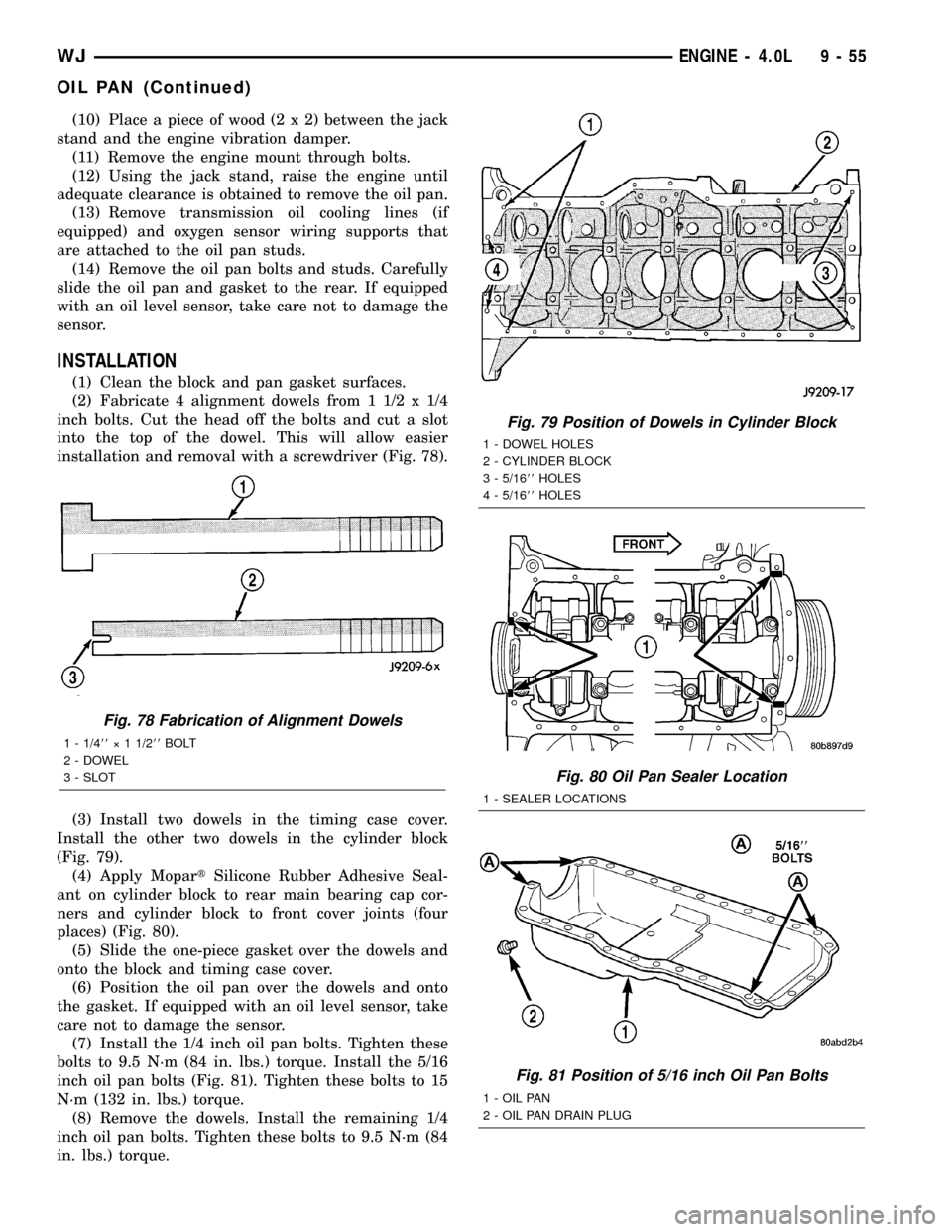
(1) Clean the block and pan gasket surfaces.
(2) Fabricate 4 alignment dowels from 1 1/2 x 1/4
inch bolts. Cut the head off the bolts and cut a slot
into the top of the dowel. This will allow easier
installation and removal with a screwdriver (Fig. 78).
(3) Install two dowels in the timing case cover.
Install the other two dowels in the cylinder block
(Fig. 79).
(4) Apply MopartSilicone Rubber Adhesive Seal-
ant on cylinder block to rear main bearing cap cor-
ners and cylinder block to front cover joints (four
places) (Fig. 80).
(5) Slide the one-piece gasket over the dowels and
onto the block and timing case cover.
(6) Position the oil pan over the dowels and onto
the gasket. If equipped with an oil level sensor, take
care not to damage the sensor.
(7) Install the 1/4 inch oil pan bolts. Tighten these
bolts to 9.5 N´m (84 in. lbs.) torque. Install the 5/16
inch oil pan bolts (Fig. 81). Tighten these bolts to 15
N´m (132 in. lbs.) torque.
(8) Remove the dowels. Install the remaining 1/4
inch oil pan bolts. Tighten these bolts to 9.5 N´m (84
in. lbs.) torque.
Fig. 78 Fabrication of Alignment Dowels
1 - 1/488ý 1 1/288BOLT
2 - DOWEL
3 - SLOT
Fig. 79 Position of Dowels in Cylinder Block
1 - DOWEL HOLES
2 - CYLINDER BLOCK
3 - 5/1688HOLES
4 - 5/1688HOLES
Fig. 80 Oil Pan Sealer Location
1 - SEALER LOCATIONS
Fig. 81 Position of 5/16 inch Oil Pan Bolts
1 - OIL PAN
2 - OIL PAN DRAIN PLUG
WJENGINE - 4.0L 9 - 55
OIL PAN (Continued)
Page 1305 of 2199

ROCKER ARM / ADJUSTER ASSEMBLY
DESCRIPTION........................107
REMOVAL............................107
INSTALLATION........................107
VALVE SPRINGS
DESCRIPTION........................108
VALVE STEM SEALS
DESCRIPTION........................108
ENGINE BLOCK
DESCRIPTION........................108
STANDARD PROCEDUREÐCYLINDER BORE
HONING...........................108
CLEANING...........................109
INSPECTION.........................109
CONNECTING ROD BEARINGS
STANDARD PROCEDURE - CONNECTING
ROD BEARING FITTING...............109
CRANKSHAFT
DESCRIPTION........................111
STANDARD PROCEDURE - MEASURING
CRANKSHAFT END PLAY..............111
REMOVAL............................112
INSPECTION..........................112
INSTALLATION........................112
CRANKSHAFT MAIN BEARINGS
STANDARD PROCEDUREÐCRANKSHAFT
MAIN BEARING - FITTING..............114
INSPECTION..........................115
CRANKSHAFT OIL SEAL - FRONT
REMOVAL............................115
INSTALLATION........................116
CRANKSHAFT OIL SEAL - REAR
REMOVAL............................117
INSTALLATION........................117
FLEX PLATE
REMOVAL............................118
INSTALLATION........................118
PISTON & CONNECTING ROD
DESCRIPTION........................118
STANDARD PROCEDUREÐPISTON FITTING . 118
REMOVAL............................118
CLEANING...........................119
INSPECTION..........................119
INSTALLATION........................120
PISTON RINGS
STANDARD PROCEDURE - PISTON RING
FITTING............................121
VIBRATION DAMPER
REMOVAL............................122
INSTALLATION........................123
STRUCTURAL COVER
DESCRIPTION........................124
OPERATION..........................124
REMOVAL............................124
INSTALLATION........................124
FRONT MOUNT
REMOVAL............................124INSTALLATION........................125
REAR MOUNT
REMOVAL............................125
INSTALLATION........................126
LUBRICATION
DESCRIPTION........................126
OPERATION..........................126
DIAGNOSIS AND TESTING
DIAGNOSIS AND TESTINGÐENGINE OIL
PRESSURE.........................128
DIAGNOSIS AND TESTINGÐREAR SEAL
AREA LEAKS........................128
DIAGNOSIS AND TESTINGÐENGINE OIL
LEAK..............................129
OIL
STANDARD PROCEDURE - ENGINE OIL....130
OIL FILTER
REMOVAL............................131
INSTALLATION........................132
OIL PAN
DESCRIPTION........................132
REMOVAL............................132
CLEANING...........................132
INSPECTION.........................132
INSTALLATION........................132
OIL PRESSURE SENSOR/SWITCH
DESCRIPTION........................133
OPERATION..........................133
REMOVAL............................133
INSTALLATION........................133
OIL PUMP
REMOVAL............................134
DISASSEMBLY........................134
CLEANING...........................134
INSPECTION.........................134
ASSEMBLY...........................135
INSTALLATION........................135
INTAKE MANIFOLD
DESCRIPTION........................136
DIAGNOSIS AND TESTINGÐINTAKE
MANIFOLD LEAKAGE.................136
REMOVAL............................136
CLEANING...........................137
INSPECTION.........................137
INSTALLATION........................137
EXHAUST MANIFOLD - LEFT
DESCRIPTION........................138
REMOVAL............................138
CLEANING...........................138
INSPECTION.........................138
INSTALLATION........................138
EXHAUST MANIFOLD - RIGHT
DESCRIPTION........................139
REMOVAL............................139
CLEANING...........................140
INSPECTION.........................141
INSTALLATION........................141
9 - 62 ENGINE - 4.7LWJ