2002 ISUZU AXIOM warning light
[x] Cancel search: warning lightPage 2042 of 2100

SUPPLEMENTAL RESTRAINT SYSTEM 9J±28
damaged, replace them. The steering column and wheel
must be dimensionally checked to determine if they are
damaged. Refer to in this Section 9J±3 of this manual.
Never use SRS parts from another vehicle. This does not
include remanufactured parts purchased from an
authorized Retailer; they may be used for SRS repairs.
Do not attempt to repair the SDM, the SRS harness, the
SRS coil assembly, the air bag assembly, the steeringwheel, or the steering column. Service of these items is
replacement only. Verify replacement part numbers.
CAUTION: P r o p e r o p e r a t i o n o f t h e S D M a n d
Supplemental Restraint System (SRS) requires that
any repairs to the vehicle structure return it to its
original production configuration.
Sensing and Diagnostic Module (SDM)
Service Precautions
WARNING:DURING SERVICE PROCEDURES, BE
VERY CAREFUL WHEN HANDLING SDM. NEVER
STRIKE OR JAR SDM. UNDER SOME
CIRCUMSTANCES, IT COULD CAUSE
DEPLOYMENT AND RESULT IN PERSONAL INJURY
OR IMPROPER OPERATION OF THE
SUPPLEMENTAL RESTRAINT SYSTEM (SRS). SDM
MOUNTING BRACKET BOLTS MUST BE
CAREFULLY TORQUED TO ASSURE PROPER
OPERATION. NEVER POWER UP THE SRS WHEN
SDM IS NOT RIGIDLY ATTACHED TO THE VEHICLE.
THE SDM COULD BE ACTIVATED WHEN POWERED
WHILE NOT RIGIDLY ATTACHED TO THE VEHICLE
WHICH COULD CAUSE DEPLOYMENT AND RESULT
IN PERSONAL INJURY.
WARNING: PROPER OPERATION OF THE SENSING
AND DIAGNOSTIC MODULE (SDM) REQUIRES THE
SDM TO BE RIGIDLY ATTACHED TO THE VEHICLE
STRUCTURE AND THAT THE ARROW ON THE
SENSOR BE POINTING TOWARD THE FRONT OF
THE VEHICLE.
SDM is specifically calibrated and is keyed to the SDM
location SRS wiring harness. Caution should be used to
ensure proper location of the SDM. The keying of the
SDM to its location and wiring harness connectors should
never be modified in the field.
Removal
1. Disable the SRS. (Refer to ªDisable the SRSº in this
manual)
2. Remove dressing panel around the radio and
disconnect cigar lighter harness.
3. Remove the transfer sift lever knob.
4. Remove the center console.
5. Remove three connector from PCM.
6. Remove PCM with bracket.(Fixed four bolts)
7. Remove right side stay between instrument panel
and floor.
8. Remove driver and passenger seat.
9. Turn over carpet to rear side.10. Remove air conditioning duct for rear seat.
(Transform the duct during removing it)
827RW023
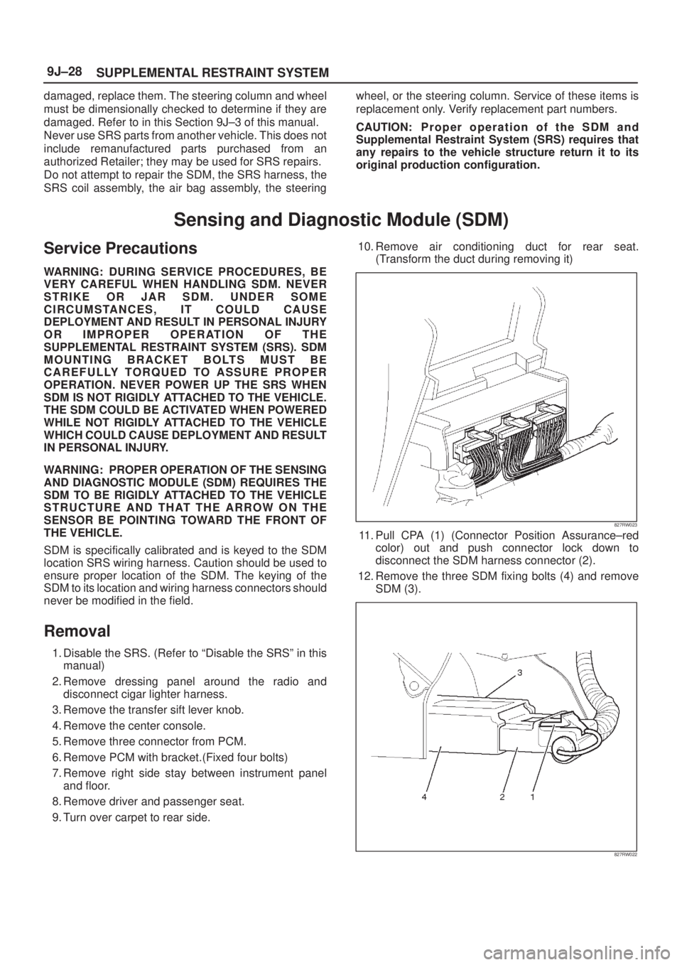
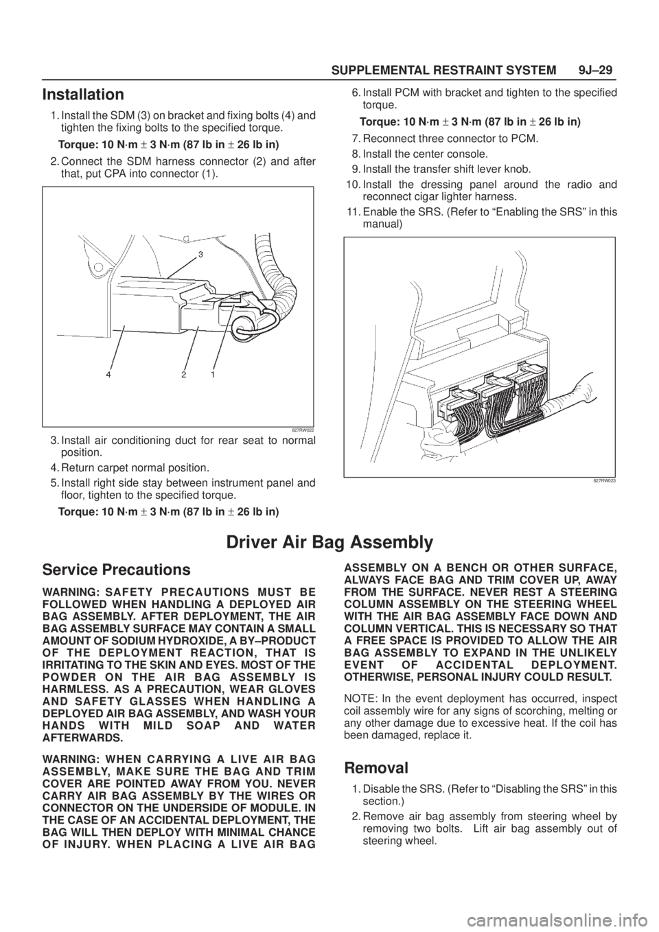
11. Pull CPA (1) (Connector Position Assurance±red
color) out and push connector lock down to
disconnect the SDM harness connector (2).
12. Remove the three SDM fixing bolts (4) and remove
SDM (3).
827RW022
Page 2043 of 2100

SUPPLEMENTAL RESTRAINT SYSTEM9J±29
Installation
1. Install the SDM (3) on bracket and fixing bolts (4) and
tighten the fixing bolts to the specified torque.
Torque: 10 N´m + 3 N´m (87 lb in + 26 lb in)
2. Connect the SDM harness connector (2) and after
that, put CPA into connector (1).
827RW022
3. Install air conditioning duct for rear seat to normal
position.
4. Return carpet normal position.
5. Install right side stay between instrument panel and
floor, tighten to the specified torque.
Torque: 10 N´m + 3 N´m (87 lb in + 26 lb in)6. Install PCM with bracket and tighten to the specified
torque.
Torque: 10 N´m + 3 N´m (87 lb in + 26 lb in)
7. Reconnect three connector to PCM.
8. Install the center console.
9. Install the transfer shift lever knob.
10. Install the dressing panel around the radio and
reconnect cigar lighter harness.
11. Enable the SRS. (Refer to ªEnabling the SRSº in this
manual)
827RW023
Driver Air Bag Assembly
Service Precautions
WARNING: S A F E T Y P R ECAUTIONS MUST BE
FOLLOWED WHEN HANDLING A DEPLOYED AIR
BAG ASSEMBLY. AFTER DEPLOYMENT, THE AIR
BAG ASSEMBLY SURFACE MAY CONTAIN A SMALL
AMOUNT OF SODIUM HYDROXIDE, A BY±PRODUCT
OF THE DEPLOYMENT REACTION, THAT IS
IRRITATING TO THE SKIN AND EYES. MOST OF THE
POWDER ON THE AIR BAG ASSEMBLY IS
HARMLESS. AS A PRECAUTION, WEAR GLOVES
AND SAFETY GLASSES WHEN HANDLING A
DEPLOYED AIR BAG ASSEMBLY, AND WASH YOUR
HANDS WITH MILD SOAP AND WATER
AFTERWARDS.
WARNING: W H E N C A R RY I N G A L I V E A I R B A G
ASSEMBLY, MAKE SURE THE BAG AND TRIM
COVER ARE POINTED AWAY FROM YOU. NEVER
CARRY AIR BAG ASSEMBLY BY THE WIRES OR
CONNECTOR ON THE UNDERSIDE OF MODULE. IN
THE CASE OF AN ACCIDENTAL DEPLOYMENT, THE
BAG WILL THEN DEPLOY WITH MINIMAL CHANCE
OF INJURY. WHEN PLACING A LIVE AIR BAGASSEMBLY ON A BENCH OR OTHER SURFACE,
ALWAYS FACE BAG AND TRIM COVER UP, AWAY
FROM THE SURFACE. NEVER REST A STEERING
COLUMN ASSEMBLY ON THE STEERING WHEEL
WITH THE AIR BAG ASSEMBLY FACE DOWN AND
COLUMN VERTICAL. THIS IS NECESSARY SO THAT
A FREE SPACE IS PROVIDED TO ALLOW THE AIR
BAG ASSEMBLY TO EXPAND IN THE UNLIKELY
EVENT OF ACCIDENTAL DEPLOYMENT.
OTHERWISE, PERSONAL INJURY COULD RESULT.
NOTE: In the event deployment has occurred, inspect
coil assembly wire for any signs of scorching, melting or
any other damage due to excessive heat. If the coil has
been damaged, replace it.
Removal
1. Disable the SRS. (Refer to ªDisabling the SRSº in this
section.)
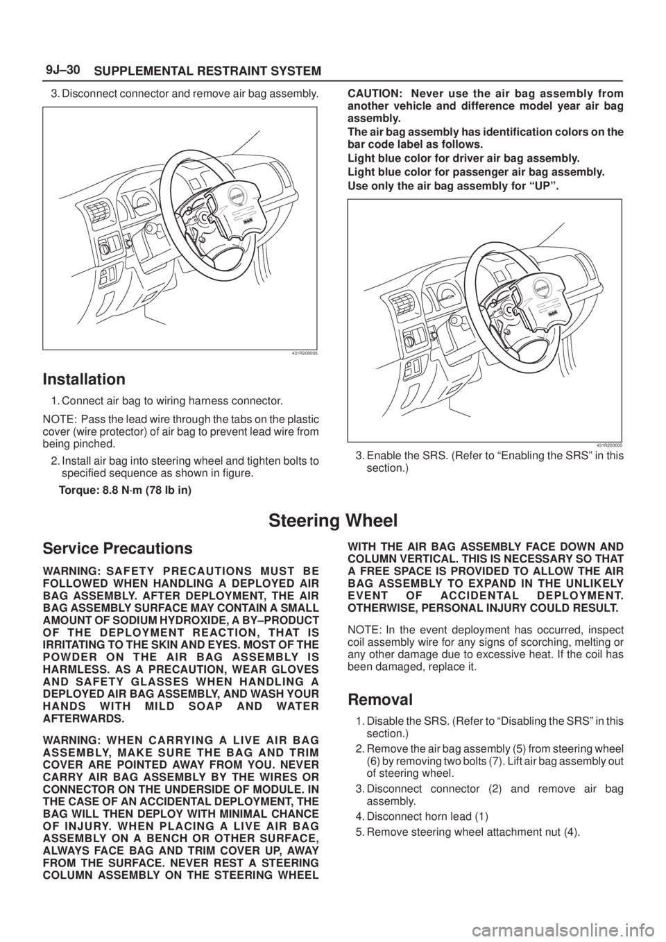
2. Remove air bag assembly from steering wheel by
removing two bolts. Lift air bag assembly out of
steering wheel.
Page 2044 of 2100

SUPPLEMENTAL RESTRAINT SYSTEM 9J±30
3. Disconnect connector and remove air bag assembly.
431R200005
Installation
1. Connect air bag to wiring harness connector.
NOTE: Pass the lead wire through the tabs on the plastic
cover (wire protector) of air bag to prevent lead wire from
being pinched.
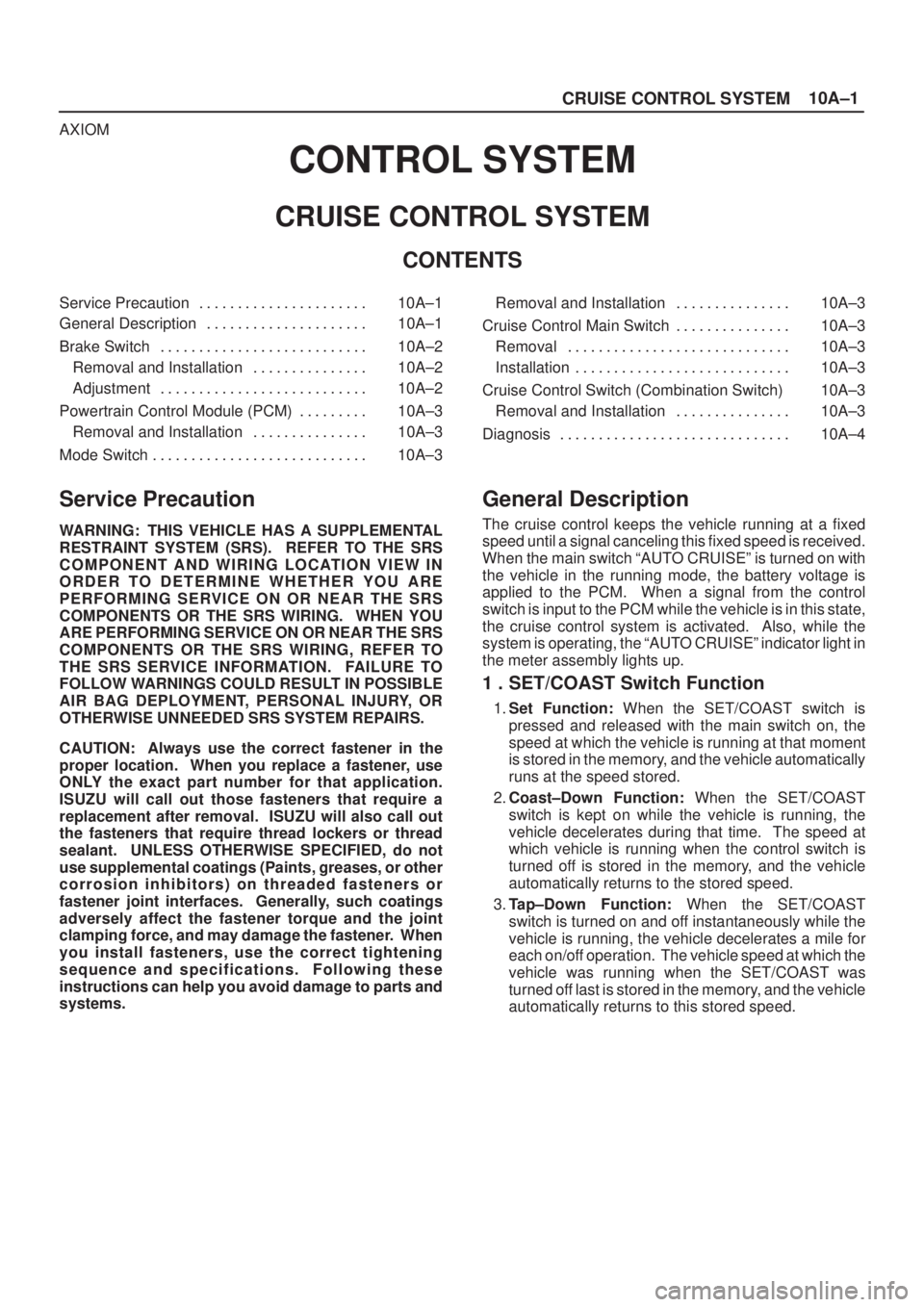
2. Install air bag into steering wheel and tighten bolts to
specified sequence as shown in figure.
Torque: 8.8 N´m (78 lb in)CAUTION: Never use the air bag assembly from
another vehicle and difference model year air bag
assembly.
The air bag assembly has identification colors on the
bar code label as follows.
Light blue color for driver air bag assembly.
Light blue color for passenger air bag assembly.
Use only the air bag assembly for ªUPº.
431R200005
3. Enable the SRS. (Refer to ªEnabling the SRSº in this
section.)
Steering Wheel
Service Precautions
WARNING: S A F E T Y P R ECAUTIONS MUST BE
FOLLOWED WHEN HANDLING A DEPLOYED AIR
BAG ASSEMBLY. AFTER DEPLOYMENT, THE AIR
BAG ASSEMBLY SURFACE MAY CONTAIN A SMALL
AMOUNT OF SODIUM HYDROXIDE, A BY±PRODUCT
OF THE DEPLOYMENT REACTION, THAT IS
IRRITATING TO THE SKIN AND EYES. MOST OF THE
POWDER ON THE AIR BAG ASSEMBLY IS
HARMLESS. AS A PRECAUTION, WEAR GLOVES
AND SAFETY GLASSES WHEN HANDLING A
DEPLOYED AIR BAG ASSEMBLY, AND WASH YOUR
HANDS WITH MILD SOAP AND WATER
AFTERWARDS.
WARNING: W H E N C A R RY I N G A L I V E A I R B A G
ASSEMBLY, MAKE SURE THE BAG AND TRIM
COVER ARE POINTED AWAY FROM YOU. NEVER
CARRY AIR BAG ASSEMBLY BY THE WIRES OR
CONNECTOR ON THE UNDERSIDE OF MODULE. IN
THE CASE OF AN ACCIDENTAL DEPLOYMENT, THE
BAG WILL THEN DEPLOY WITH MINIMAL CHANCE
OF INJURY. WHEN PLACING A LIVE AIR BAG
ASSEMBLY ON A BENCH OR OTHER SURFACE,
ALWAYS FACE BAG AND TRIM COVER UP, AWAY
FROM THE SURFACE. NEVER REST A STEERING
COLUMN ASSEMBLY ON THE STEERING WHEELWITH THE AIR BAG ASSEMBLY FACE DOWN AND
COLUMN VERTICAL. THIS IS NECESSARY SO THAT
A FREE SPACE IS PROVIDED TO ALLOW THE AIR
BAG ASSEMBLY TO EXPAND IN THE UNLIKELY
EVENT OF ACCIDENTAL DEPLOYMENT.
OTHERWISE, PERSONAL INJURY COULD RESULT.
NOTE: In the event deployment has occurred, inspect
coil assembly wire for any signs of scorching, melting or
any other damage due to excessive heat. If the coil has
been damaged, replace it.
Removal
1. Disable the SRS. (Refer to ªDisabling the SRSº in this
section.)
2. Remove the air bag assembly (5) from steering wheel
(6) by removing two bolts (7). Lift air bag assembly out
of steering wheel.
3. Disconnect connector (2) and remove air bag
assembly.
4. Disconnect horn lead (1)
5. Remove steering wheel attachment nut (4).
Page 2097 of 2100

10A±1
CRUISE CONTROL SYSTEM
AXIOM
CONTROL SYSTEM
CRUISE CONTROL SYSTEM
CONTENTS
Service Precaution 10A±1. . . . . . . . . . . . . . . . . . . . . .
General Description 10A±1. . . . . . . . . . . . . . . . . . . . .
Brake Switch 10A±2. . . . . . . . . . . . . . . . . . . . . . . . . . .
Removal and Installation 10A±2. . . . . . . . . . . . . . .
Adjustment 10A±2. . . . . . . . . . . . . . . . . . . . . . . . . . .
Powertrain Control Module (PCM) 10A±3. . . . . . . . .
Removal and Installation 10A±3. . . . . . . . . . . . . . .
Mode Switch 10A±3. . . . . . . . . . . . . . . . . . . . . . . . . . . . Removal and Installation 10A±3. . . . . . . . . . . . . . .
Cruise Control Main Switch 10A±3. . . . . . . . . . . . . . .
Removal 10A±3. . . . . . . . . . . . . . . . . . . . . . . . . . . . .
Installation 10A±3. . . . . . . . . . . . . . . . . . . . . . . . . . . .
Cruise Control Switch (Combination Switch) 10A±3
Removal and Installation 10A±3. . . . . . . . . . . . . . .
Diagnosis 10A±4. . . . . . . . . . . . . . . . . . . . . . . . . . . . . .
Service Precaution
WARNING: THIS VEHICLE HAS A SUPPLEMENTAL
RESTRAINT SYSTEM (SRS). REFER TO THE SRS
COMPONENT AND WIRING LOCATION VIEW IN
ORDER TO DETERMINE WHETHER YOU ARE
PERFORMING SERVICE ON OR NEAR THE SRS
COMPONENTS OR THE SRS WIRING. WHEN YOU
ARE PERFORMING SERVICE ON OR NEAR THE SRS
COMPONENTS OR THE SRS WIRING, REFER TO
THE SRS SERVICE INFORMATION. FAILURE TO
FOLLOW WARNINGS COULD RESULT IN POSSIBLE
AIR BAG DEPLOYMENT, PERSONAL INJURY, OR
OTHERWISE UNNEEDED SRS SYSTEM REPAIRS.
CAUTION: Always use the correct fastener in the
proper location. When you replace a fastener, use
ONLY the exact part number for that application.
ISUZU will call out those fasteners that require a
replacement after removal. ISUZU will also call out
the fasteners that require thread lockers or thread
sealant. UNLESS OTHERWISE SPECIFIED, do not
use supplemental coatings (Paints, greases, or other
corrosion inhibitors) on threaded fasteners or
fastener joint interfaces. Generally, such coatings
adversely affect the fastener torque and the joint
clamping force, and may damage the fastener. When
you install fasteners, use the correct tightening
sequence and specifications. Following these
instructions can help you avoid damage to parts and
systems.
General Description
The cruise control keeps the vehicle running at a fixed
speed until a signal canceling this fixed speed is received.
When the main switch ªAUTO CRUISEº is turned on with
the vehicle in the running mode, the battery voltage is
applied to the PCM. When a signal from the control
switch is input to the PCM while the vehicle is in this state,
the cruise control system is activated. Also, while the
system is operating, the ªAUTO CRUISEº indicator light in
the meter assembly lights up.
1 . SET/COAST Switch Function
1.Set Function: When the SET/COAST switch is
pressed and released with the main switch on, the
speed at which the vehicle is running at that moment
is stored in the memory, and the vehicle automatically
runs at the speed stored.
2.Coast±Down Function: When the SET/COAST
switch is kept on while the vehicle is running, the
vehicle decelerates during that time. The speed at
which vehicle is running when the control switch is
turned off is stored in the memory, and the vehicle
automatically returns to the stored speed.
3.Tap±Down Function: When the SET/COAST
switch is turned on and off instantaneously while the
vehicle is running, the vehicle decelerates a mile for
each on/off operation. The vehicle speed at which the
vehicle was running when the SET/COAST was
turned off last is stored in the memory, and the vehicle
automatically returns to this stored speed.