Page 1955 of 2100
 Door Mirror Cover
(2) Power Window Switch
(3) Door Trim Panel
(4) Inside Lock Bracket
(5) I")
SECURITY AND LOCKS8H±5
Front Outside Handle
Front Outside Handle and Associated Parts
635R200008
Legend
(1) Door Mirror Cover
(2) Power Window Switch
(3) Door Trim Panel
(4) Inside Lock Bracket
(5) Inside Handle(6) Pull Box
(7) Pull Box Bracket
(8) Waterproof Sheet
(9) Door Lock Assembly
(10) Door Locking Cylinder
(11) Outside Handle
Removal
1. Disconnect the battery ground cable.
2. Remove the door trim panel.
�Refer to
Front Door Lock Assembly in this section.
3. Remove the waterproof sheet.
�Taking notice of the door harness, peel the
waterproof sheet off the door panel carefully.
4. Disconnect the locking links and remove the outside
handle.
5. Remove the fixing clip to remove the door lock
cylinder.
Installation
To install, follow the removal steps in the reverse order,
noting the following points:
1. Be sure to install the door lock cylinder at a specified
angle to the outside handle.
2. Check for smooth outside handle and lock cylinder
operation.
3. Tighten the outside handle fixing bolts to the specified
torque.
Torque 7 N´m (61 Ib in)
Page 1956 of 2100
8H±6SECURITY AND LOCKS
Rear Door Lock Assembly
Rear Door Lock Assembly and Associated Parts
655R200007
Legend
(1) Outside Handle
(2) Door Lock Assembly
(3) Pull Box Bracket
(4) Pull Box(5) Door Trim Panel
(6) Power Window Switch
(7) Inside Handle
(8) Inside Lock Bracket
(9) Waterproof Sheet
Removal
1. Disconnect the battery ground cable.
2. Remove the pull box.
�Remove the fixing screw.
655R200003
Page 1957 of 2100
SECURITY AND LOCKS8H±7
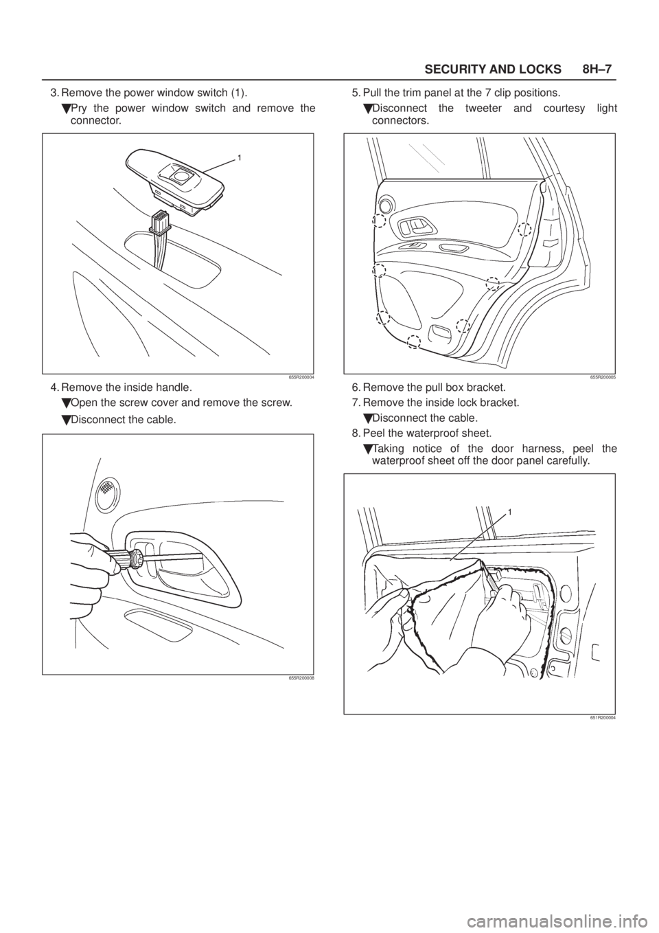
3. Remove the power window switch (1).
�Pry the power window switch and remove the
connector.
655R200004
4. Remove the inside handle.
�Open the screw cover and remove the screw.
�Disconnect the cable.
655R200008
5. Pull the trim panel at the 7 clip positions.
�Disconnect the tweeter and courtesy light
connectors.
655R200005
6. Remove the pull box bracket.
7. Remove the inside lock bracket.
�Disconnect the cable.
8. Peel the waterproof sheet.
�Taking notice of the door harness, peel the
waterproof sheet off the door panel carefully.
651R200004
Page 1958 of 2100
8H±8SECURITY AND LOCKS
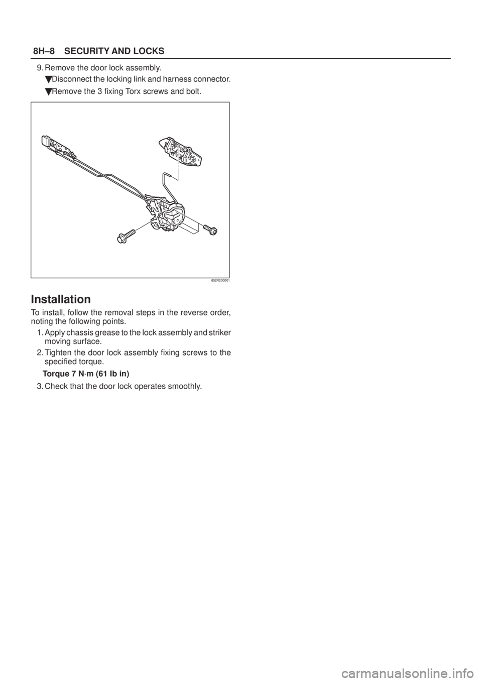
9. Remove the door lock assembly.
�Disconnect the locking link and harness connector.
�Remove the 3 fixing Torx screws and bolt.
652R200001
Installation
To install, follow the removal steps in the reverse order,
noting the following points.
1. Apply chassis grease to the lock assembly and striker
moving surface.
2. Tighten the door lock assembly fixing screws to the
specified torque.
Torque 7 N´m (61 Ib in)
3. Check that the door lock operates smoothly.
Page 1959 of 2100
SECURITY AND LOCKS8H±9
Rear Outside Handle
Rear Outside Handle and Associated Parts
655R200007
Legend
(1) Outside Handle
(2) Door Lock Assembly
(3) Pull Box Bracket
(4) Pull Box(5) Door Trim Panel
(6) Power Window Switch
(7) Inside Handle
(8) Inside Lock Bracket
(9) Waterproof Sheet
Removal
1. Disconnect the battery ground cable.
2. Remove the door trim panel.
�Refer to
Rear Door Lock Assembly in this section.
3. Peel the waterproof sheet.
�Taking notice of the door harness, peel the
waterproof sheet off the door panel carefully.
4. Disconnect the locking link and remove fixing bolts to
remove the outside handle.
Installation
To install, follow the removal steps in the reverse order,
noting the following points.
1. Check that the outside handle operates smoothly.
2. Tighten the outside handle fixing bolts to the specified
torque.
Torque 7 N´m (61 Ib in)
Page 1962 of 2100
 Key (Actual size)
(2) Key Code Tag(3) Position
(4) Level
One key is used for the ignition, door, and tailgate lock
cylinders. The keys are c")
8H±12SECURITY AND LOCKS
Key
Key Coding
730RX001
Legend
(1) Key (Actual size)
(2) Key Code Tag(3) Position
(4) Level
One key is used for the ignition, door, and tailgate lock
cylinders. The keys are cut on both edges to make them
reversible.
Key identification is obtained from the five character key
code stamped on the key code tag. From this key code,
the key code cutting combination can be determined from
a code list (available to owners of key cutting equipment
from suppliers).
If key codes are not available from records or tags, the
key code can be obtained from the right hand door lock
cylinder (if lock has not been replaced). Lock cylinders
supplied by the factory as service parts are unmarked.
If the original key is available, the key code cutting
combination can be determined by laying the key on the
diagram shown in the figure.Key Styles
730RX002
Legend
(1) Blank Key Style ªAº
(2) Blank Key Style ªBº
The keys come in styles A or B depending on the key code
cutting combination. When the first position in the
combination is a 1, 2 or 3, Style A is used. When the first
position is a 4, Style B (factory pre-cut key) is used.
Page 1963 of 2100

switch, door lock actuator for the front and rear door,
tailgate lock actuato")
SECURITY AND LOCKS8H±13
Power Door Lock System
General Description
The circuit consists of the door lock (& power window)
switch, door lock actuator for the front and rear door,
tailgate lock actuator and the door lock key switch.
The front door lock switch±LH is always provided with the
battery voltage.
The key or the inside lock button on both driver's and front
passenger's door can activate the lock mechanism of all
the doors (including the tailgate).
When the driver's door lock switch or the front
passenger's door lock switch is turned on, current flows
for about one second to the door lock actuator of each
door connected in parallel with the front door lock (&
power window) switch±LH to activate the actuator to lock
and unlock the doors.
Door Lock Key Switch
Removal and Installation
�Refer to the Front Door Lock Assembly removal and
installation steps in this section.
Front Door Lock Actuator
Removal and Installation
�Refer to the Front Door Lock Assembly removal and
installation steps in this section.
Rear Door Lock Actuator
Removal and Installation
�Refer to the Rear Door Lock Assembly removal and
installation steps in this section.
Tailgate Lock Actuator
Removal and Installation
�Refer to the Tailgate Lock Assembly removal and
installation steps in this section.
Page 1964 of 2100

8H±14SECURITY AND LOCKS
Anti-Theft System
General Description
The circuit consists of the starter switch, anti±theft &
keyless entry controller, anti±theft horn, front door and
tailgate key switch (detect and tamper) switch, door lock
actuator for each door, engine hood switch, clutch start
switch (M/T), ANTI±THEFT indicator light and mode
switch (A/T).
The system operates as follows: After locking the starter
switch and removing the starter key (this sets the alarm),
if the door is unlocked in any way other than with the
proper key, the headlights will start flashing, the horn
sounds, and the starter circuit is disabled. (However, the
engine hood and all the doors must be locked and closed.)
Once the system has been placed in the warning or alarm
condition, it can be released only when the starter switch
is shifted from ªOFFº to ªACCº by the starter key, or when
the lock of the front door or the tailgate is released (to
activate the detect switch) by the starter key.
Anti±Theft & Keyless Entry Control-
ler
Removal
1. Disconnect the battery ground cable.
2. Remove the glove box from the instrument panel
assembly (1).
�Refer to
the Instrument Panel Assembly in Body
Structure section.
3. Remove the anti±theft & keyless entry controller (2).
�Disconnect the connector.
�Remove two fixing screws.
826RW007
Installation
To install, follow the removal steps in the reverse order.
Anti±Theft Indicator
Removal and Installation
Refer to GPS in Entertainment section.
Anti±Theft Horn
Removal
1. Disconnect the battery ground cable.
2. Remove the anti±theft horn (1).
�Disconnect the connector.
�Remove a fixing bolt.
828RW001
Installation
To install, follow the removal steps in the reverse order.
 Outside Handle
(2) Door Lock Assembly
(3) Pull Box Bracket
(4) Pull Box(5) Door Trim")
 Outside Handle
(2) Door Lock Assembly
(3) Pull Box Bracket
(4) Pull Box(5) Door Trim Panel
(6")