Page 257 of 2100
REAR SUSPENSION3D±31
�Install the rubber bushing (Frame side) by using
Installer J±39215.
NOTE: When mounting rubber bushings, do not use
grease on bushings or any other nearby parts.
901RW061
3. Rubber bushing (Axle side)
�Remove the rubber bushing (Axle side) by using
remover J±39792.
901RW062
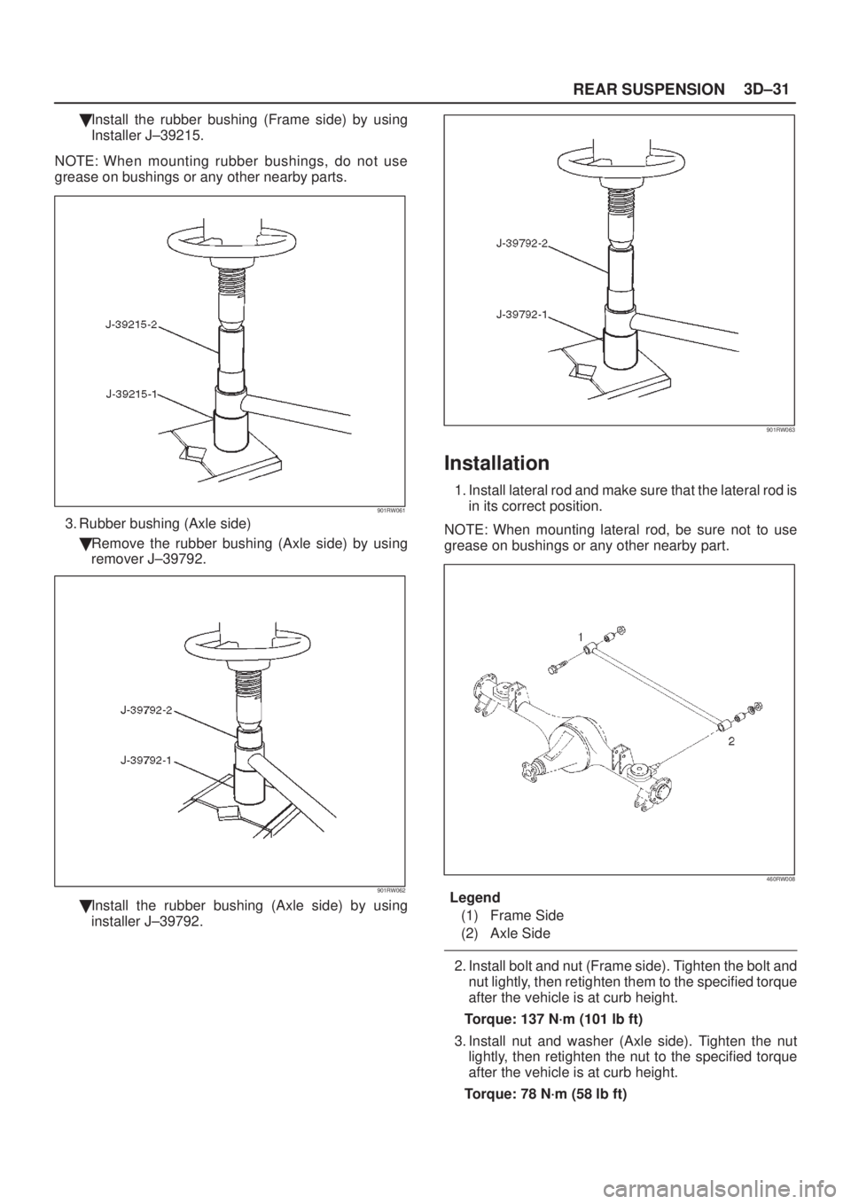
�Install the rubber bushing (Axle side) by using
installer J±39792.
901RW063
Installation
1. Install lateral rod and make sure that the lateral rod is
in its correct position.
NOTE: When mounting lateral rod, be sure not to use
grease on bushings or any other nearby part.
460RW008
Legend
(1) Frame Side
(2) Axle Side
2. Install bolt and nut (Frame side). Tighten the bolt and
nut lightly, then retighten them to the specified torque
after the vehicle is at curb height.
Torque: 137 N´m (101 lb ft)
3. Install nut and washer (Axle side). Tighten the nut
lightly, then retighten the nut to the specified torque
after the vehicle is at curb height.
Torque: 78 N´m (58 lb ft)
Page 258 of 2100
3D±32REAR SUSPENSION
Stabilizer Bar
Stabilizer Bar and Associated Parts
460R200003
Legend
(1) Bracket and Bolt
(2) Link(3) Nut
(4) Stabilizer Bar
(5) Rubber Bushing
Removal
1. Raise the vehicle and support the frame with suitable
safety stands.
2. Remove wheel and tire assembly. Refer to
Wheel in
this section.
3. Remove nut.
4. Remove link.
5. Remove bracket.
6. Remove rubber bushing.
Inspection and Repair
Make necessary correction or parts replacement if wear,
damage, corrosion or any other abnormal condition are
found through inspection.
Check the following parts:
�Stabilizer bar
�Rubber bushing
�Link
Page 259 of 2100
REAR SUSPENSION3D±33
Installation
1. Install rubber bushing.
2. Install bracket to axle housing and tighten to the
specified torque.
Torque: 25 N´m (18 lb ft)
3. Install link.
4. Install nut, then tighten the nut to the specified torque.
Torque: 50 N´m (37 lb ft)
460R200002
Page 260 of 2100
3D±34REAR SUSPENSION
Main Data and Specifications
General Specifications
Rear suspensionType5±Link, coil spring type with stabilizer bar.
Coil springFree length370.5 mm (14.59 in)
Spring diameter12.4 mm (0.49 in)
Coil diameter
(inner)105 mm (4.13 in)
Effective No. of
turns5.21
Total No. of turns6.71
Shock absorberTypeHydraulic, double acting, telescopic
Piston diameter30 mm (1.18 in)
Stroke159 mm (6.26 in)
Extended length518 mm (20.39 in)
Compressed
length359 mm (14.13 in)
Stabilizer barDiameter18 mm (0.71 in)
Page 261 of 2100
REAR SUSPENSION3D±35
Torque Specifications
E03R200006
Page 262 of 2100
3D±36REAR SUSPENSION
Special Tools
ILLUSTRATIONTOOL NO.
TOOL NAME
J±39214
Remover and Installer;
Trailing link bushing
J±43008
Remover and Installer;
Upper link bushing
J±39792
Remover and Installer;
Lateral rod bushing
(Axle side)
J±39215
Remover and Installer;
Lateral rod bushing
(Frame side)
Page 263 of 2100

WHEEL AND TIRE SYSTEM3E±1
AXIOM
SUSPENSION
WHEEL AND TIRE SYSTEM
CONTENTS
Service Precaution 3E±1. . . . . . . . . . . . . . . . . . . . . .
General Description 3E±2. . . . . . . . . . . . . . . . . . . . .
Diagnosis 3E±3. . . . . . . . . . . . . . . . . . . . . . . . . . . . . .
Wheel 3E±11. . . . . . . . . . . . . . . . . . . . . . . . . . . . . . . . .
Wheel and Associated Parts 3E±11. . . . . . . . . . . .
Removal 3E±11. . . . . . . . . . . . . . . . . . . . . . . . . . . . . Installation 3E±11. . . . . . . . . . . . . . . . . . . . . . . . . . . .
Tire 3E±12. . . . . . . . . . . . . . . . . . . . . . . . . . . . . . . . . . . .
Tire Replacement 3E±12. . . . . . . . . . . . . . . . . . . . . .
General Balance Procedure 3E±12. . . . . . . . . . . . . .
Balancing Wheel and Tire 3E±13. . . . . . . . . . . . . . . .
Main Data and Specifications 3E±14. . . . . . . . . . . . .
Service Precaution
WARNING: THIS VEHICLE HAS A SUPPLEMENTAL
RESTRAINT SYSTEM (SRS). REFER TO THE SRS
COMPONENT AND WIRING LOCATION VIEW IN
ORDER TO DETERMINE WHETHER YOU ARE
PERFORMING SERVICE ON OR NEAR THE SRS
COMPONENTS OR THE SRS WIRING. WHEN YOU
ARE PERFORMING SERVICE ON OR NEAR THE SRS
COMPONENTS OR THE SRS WIRING, REFER TO
THE SRS SERVICE INFORMATION. FAILURE TO
FOLLOW WARNINGS COULD RESULT IN POSSIBLE
AIR BAG DEPLOYMENT, PERSONAL INJURY, OR
OTHERWISE UNNEEDED SRS SYSTEM REPAIRS.CAUTION: Always use the correct fastener in the
proper location. When you replace a fastener, use
ONLY the exact part number for that application.
ISUZU will call out those fasteners that require a
replacement after removal. ISUZU will also call out
the fasteners that require thread lockers or thread
sealant. UNLESS OTHERWISE SPECIFIED, do not
use supplemental coatings (Paints, greases, or other
corrosion inhibitors) on threaded fasteners or
fastener joint interfaces. Generally, such coatings
adversely affect the fastener torque and the joint
clamping force, and may damage the fastener. When
you install fasteners, use the correct tightening
sequence and specifications. Following these
instructions can help you avoid damage to parts and
systems.
Page 264 of 2100
3E±2WHEEL AND TIRE SYSTEM
General Description
480R200001
Replacement wheels or tires must be equivalent to the
originals in load capacity, specified dimension and
mounting configuration. Improper size or type may affect
bearing life, brake performance, speedometer/odometer
calibration, vehicle ground clearance and tire clearance
to the body and chassis. All models are equipped with
metric sized tubeless steel belted radial tires. Correct tire
pressures and driving habits have an important influence
on tire life. Heavy cornering, excessively rapid
acceleration and unnecessary sharp braking increase
premature and uneven wear.
 Bracket and Bolt
(2) Link(3) Nut
(4) Stabilizer Bar
(5) Rubber Bushing
Removal
1. Raise the vehicle and s")

3. Install link.
4. Install nut, then t")

Spring diameter12.")


