Page 412 of 2100
4B2±33
DRIVE LINE CONTROL SYSTEM (TOD)
Getting Started
�Before operating the Isuzu PCMCIA card with the
Tech 2, the following steps must be performed:
1. The Isuzu 02 System PCMCIA card (1) inserts into
the Tech 2 (4).
2. Connect the SAE 16/19 adapter (2) to the DLC cable
(4).
3. Connect the DLC cable to the Tech 2 (4)
4. Mark sure the vehicle ignition is off.
5. Connect the Tech 2 SAE 16/19 adapter to the vehicle
DLC connector.
826R200011
6. The vehicle ignition turns on.
7. Power up the Tech 2.
8. Verify the Tech 2 power up display.
060RW009
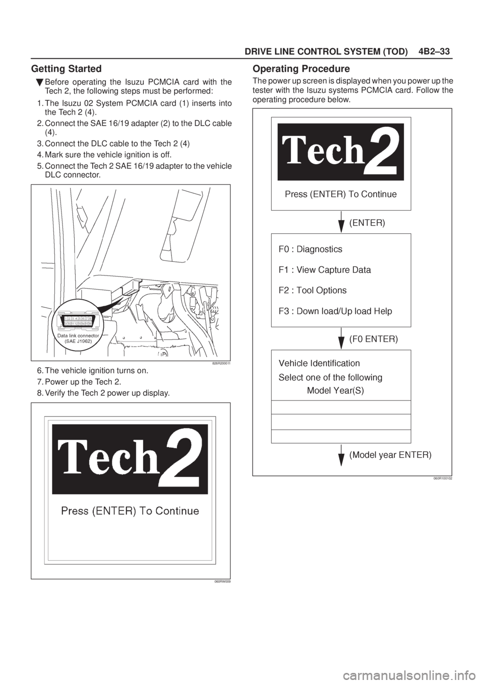
Operating Procedure
The power up screen is displayed when you power up the
tester with the Isuzu systems PCMCIA card. Follow the
operating procedure below.
060R100102
Page 477 of 2100
DRIVE LINE CONTROL SYSTEM (TOD) 4B2±98
Chart GThe trouble codes are displayed.
Function of circuitÐ
Fail condition
Indicator lamp state
TOD switch positionÐ
D04R200009
Page 633 of 2100
5A±14BRAKE CONTROL SYSTEM
Getting Started
�Before operating the Isuzu PCMCIA card with the
Tech 2, the following steps must be performed:
1. The Isuzu 98 System PCMCIA card (1) inserts into
the Tech 2 (4).
2. Connect the SAE 16/19 adapter (2) to the DLC cable
(3).
3. Connect the DLC cable to the Tech 2 (4).
4. Make sure the vehicle ignition is off.
5. Connect the Tech 2 SAE 16/19 adapter to the vehicle
DLC.
826R200011
6. The vehicle ignition turns on.
7. Power up the Tech 2.
8. Verify the Tech 2 power up display.
060RW009
Operating Procedure
The power up screen is displayed when you power up the
tester with the Isuzu systems PCMCIA card. Follow the
operating procedure below.
060R100102
Page 635 of 2100
�S")
5A±16BRAKE CONTROL SYSTEM
DATA LIST
The data displayed by DATA LIST are as follows:
Display
ContentOK/NG Criteria for Data
Front Left Wheel Speed
Front Right Wheel Speed
Rear Wheel Speedskm/h (MPH)�Start the vehicle and make sure of linear change in
each wheel speed.
�Turn each wheel by hand and make sure that each
speed data change.
Warning LampON/OFF�To be OFF usually
ABS StateON/OFF�To be OFF usually
ABS RelayActive/Inactive�To be Active usually
4 Wheel DriveActive/Inactive�2WD: Inactive
�4WD: Active
Brake SwitchActive/Inactive�Inactive (Released)
�Active (Pressed)
Brake Fluid LevelNormal or not�To be Normal usually
Return PumpActive/Inactive�To be Inactive usually
DRP (Dynamic Rear
Proportioning)Active/Inactive�To be Inactive usually
Rear Dump Valve CommandedActive/Inactive�To be Inactive usually
Rear Dump Valve Feedback
Rear Isolation Valve
Commanded
Rear Isolation Valve Feedback
FL Dump Valve CommandedActive/Inactive�To be Inactive usually
FL Dump Valve Feedback
FL Isolation Valve Commanded
FL Isolation Valve Feedback
FR Dump Valve CommandedActive/Inactive�To be Inactive usually
FR Dump Valve Feedback
FR Isolation Valve
Commanded
FR Isolation Valve Feedback
G±SensorVoltage�2.50V when vehicle is stopped
Battery VoltageVoltage�Between 10±16.9V
Page 655 of 2100

5A±36BRAKE CONTROL SYSTEM
Diagnosis By ªABSº Warning Light
Illumination Pattern
In the event that there is abnormality in the ªABSº warning
light illumination pattern while the key is in the ON position
or if the warning light is actuated while driving, refer to the
flow chart below for the correct diagnostic procedure.
No.
ConditionªABSº Warning Light Illumination PatternDiagnostic
1Warning light is
actuated normallyNormal
2Warning light is not litWarning light lighting circuit
trouble"Go to Chart B-1
3Warning light remains
ONDiagnostic trouble codes are
stored.
Display diagnostic trouble
codes and diagnose on a
code basis according to the
flow charts.
4Warning light is
actuated while drivingDiagnostic trouble codes are
stored.
Display diagnostic trouble
codes and diagnose on a
code basis according to the
flow charts.
5Warning light goes at
12 km/h (8 mph) or
higher (After repairing
the faulty part)Even after repairing the
faulty part the warning light
(W/L) dose not go out if
vehicle is at a stop.
Turn the ignition switch to the
ON position and drive the
vehicle at 12 km/h (8 mph) or
higher to make sure that the
warning light goes out.
Page 656 of 2100

When the warning light in the meter remains ON, the
EHCU stores the fault identification and disables the
ABS.
How to display and erase DTCs")
5A±37
BRAKE CONTROL SYSTEM
Diagnostic Trouble Codes (DTCs)
When the warning light in the meter remains ON, the
EHCU stores the fault identification and disables the
ABS.
How to display and erase DTCs:
NOTE:
�DTCs can be displayed also by TECH 2. Use
ªDiagnostic Trouble Codesº mode.1. How to start DTC display:
�Confirm that the vehicle has come to a complete
stop (with the wheels standing still) and that the
brake pedal is not depressed. (Unless these two
condition are satisfied, DTC display cannot be
started.)
�With IGN OFF, connect #12 terminal with #4
terminal or # 5 terminal (GND) . Then turn IGN ON.
The DLC is located behind the driver side kick panel
350R200001
�Keep #12 terminal connected with #4 terminal or # 5
terminal (GND) during DTC display. (If #12 terminal
is separated from #4 terminal or # 5 terminal (GND)
during display, display will stop.)
2. DTC display:
�DTC is displayed by blinking warning light.
�Double-digit display.
�First, normal DTC 12 is displayed three times and
then any other DTCs are displayed three times. (If
no other DTCs have been stored, the display of DTC
12 will be repeated.)3. How to erase code:
�Conduct brake switch ON/OFF operation 6 or more
times within 3 seconds of self-diagnosis startup.
�The code cannot be erased if more than 3 seconds
have passed since self-diagnosis startup, or if
self-diagnosis has started with brake switched on
(brake pedaled).
B05RW005
Page 657 of 2100
5A±38BRAKE CONTROL SYSTEM
4. Notes
�If the following should occur during Diagnostic
Trouble Code (DTC) display, the display will be
discontinued. After initial check, the status that is
under the control of ABS will be returned :
± The vehicle starts (The wheels turn) or the brake
pedal is depressed.
�Up to 3 different codes can be stored.
�If the ABS should turn OFF due to an intermittent
defect, the system will be restored at the next key
cycle, if the initial check finds no abnormality (when
IGN is switched from OFF to ON).
5. An example of DTC display
B05R100001
After displaying DTC 12 three times, one DTC after
another is displayed, starting with the most recent
one. (However, display is discontinued after about 5
minutes.)
B05R100002
The DTC 12 is displayed repeatedly. (display is
discontinued after about 5 minutes after)
Page 658 of 2100
. Warning light (W/L)
is not activated.
StepActionYe sNo
1Is W/L fuse disconnected?Replace fuse.
Go t")
5A±39
BRAKE CONTROL SYSTEM
Chart B-1 With the key in the ON position (Before starting the engine). Warning light (W/L)
is not activated.
StepActionYe sNo
1Is W/L fuse disconnected?Replace fuse.
Go to
Step 5Go to Step 2
2Is W/L burnt out?Replace W/L
bulb.
Go to
Step 5Go to Step 3
31. Turn the key off.
2. Disconnect coil integrated module connector (C-6).
3. Turn the key ON.
Is the check voltage between coil integrated module connector
(C-6) terminals 6 and 7 the battery voltage?
Go to Step 4
Repair harness
and connector.
Go to
Step 5
4Is there the continuity between coil integrated module connector
(C-6) terminals, 1 and 7 and body ground.Check harness
for suspected
disconnection
No fault found:
Replace EHCU.
Go to
Step 5
Repair harness
and connector.
Go to
Step 5
5Reconnect all components, ensure all components are properly
mounted.
Was this step finished?Repeat the ªBasic
diagnostic flow
chartº
Go to Step 5
Chart B-2 CPU Error (DTC 14 (Flash out) / C0271, C0272, C0273, C0284 (Serial
communications))
StepActionYe sNo
11. Turn the key off.
2. Disconnected coil integrated module connector.
3. Inspect coil integrated module ground.
Is there the continuity between the coil integrated module
connector terminals, 2 (C-5) and 7 (C-6) and body ground?
Go to Step 2
Repair the body
ground harness.
Go to
Step 3
21. Turn the key off, connect the coil integrated module connector.
2. Erase the trouble code.
3. Turn Ignition off, then on, to perform system self-check.
4. If warning light remains on, display trouble codes once again.
Is the trouble code the DTC 14 (Flash out) / C0271, C0272,
C0273, C0284 (Serial communications)?
Replace EHCU.
Go to
Step 3
Inspect in
accordance with
the DTC
displayed.
31. Reconnect all components, ensure all components are
properly mounted.
2. Clear diagnostic trouble code.
Was this step finished?
Repeat the ªBasic
diagnostic flow
chartº
Go to Step 3
 4B2±98
Chart GThe trouble codes are displayed.
Function of circuitÐ
Fail condition
Indicator lamp state
TOD switch positionÐ
D04R200009")

