Page 1700 of 2100
TRANSMISSION CONTROL SYSTEM (4L30±E)7A1±13
5. If problem solved: GO TO CHECK TRANS
INDICATOR.
NO: Replace Powertrain Control Module (PCM).
D07R200003
Tech 2 OBD II Connection
In order to access OBD II Powertrain Control Module
(PCM) data, use of the Tech 2 scan tool kit (7000086) is
required.
1. The electronic diagnosis equipment is composed of:
1. Tech 2 hand held scan tool unit (7000057) and
DLC cable (3000095).
901RW176
2. SAE 16/19 adaptor (3000098) (1), RS 232 loop
back connector (3000112) (2), and PCMCIA card
(3000117) (3).
F07RW033
Page 1701 of 2100
7A1±14
TRANSMISSION CONTROL SYSTEM (4L30±E)
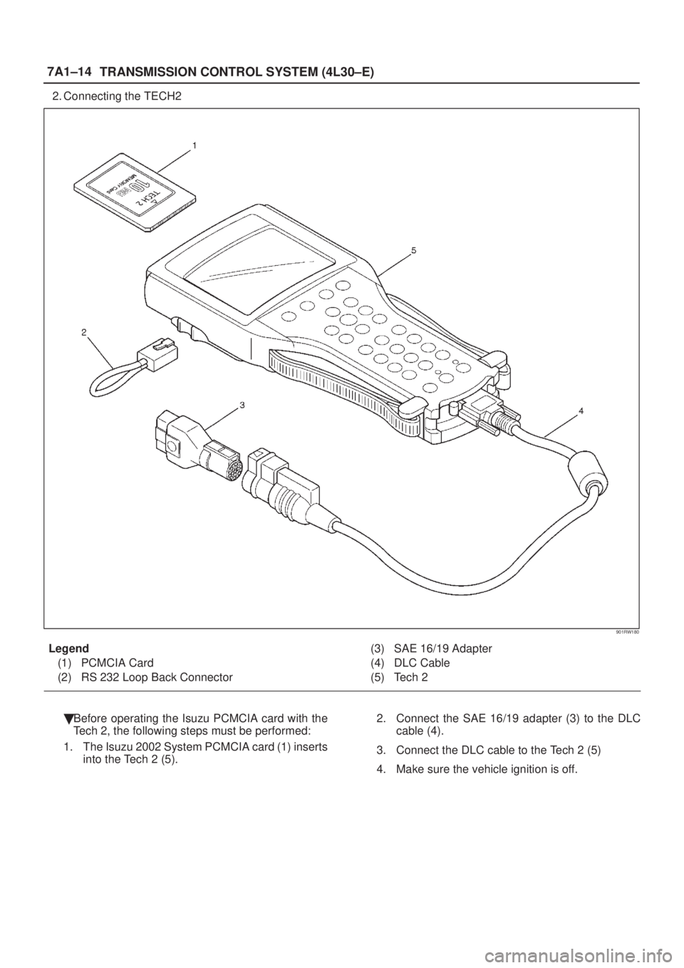
2. Connecting the TECH2
901RW180
Legend
(1) PCMCIA Card
(2) RS 232 Loop Back Connector(3) SAE 16/19 Adapter
(4) DLC Cable
(5) Tech 2
�Before operating the Isuzu PCMCIA card with the
Tech 2, the following steps must be performed:
1. The Isuzu 2002 System PCMCIA card (1) inserts
into the Tech 2 (5).2. Connect the SAE 16/19 adapter (3) to the DLC
cable (4).
3. Connect the DLC cable to the Tech 2 (5)
4. Make sure the vehicle ignition is off.
Page 1702 of 2100
TRANSMISSION CONTROL SYSTEM (4L30±E)7A1±15
5. Connect the Tech 2 SAE 16/19 adaptor to the
vehicle DLC.
826R200011
6. The vehicle ignition turns on.
7. Verify the Tech 2 power up display.
060RW009
NOTE: The RS232 Loop back connector is only to use for
diagnosis of Tech 2 and refer to
user guide of the Tech 2.
8. The power up screen is displayed when you
power up the tester with the Isuzu systems
PCMCIA card. Follow the operating procedure
below.
060R200032
Page 1703 of 2100
7A1±16
TRANSMISSION CONTROL SYSTEM (4L30±E)
060R200033
Once the test vehicle has been identified an ªApplication
(Powertrain) Menuº screen appears. Please select the
appropriate application.
The following table shows, which functions are used for
the available equipment versions.
F0: Diagnostic Trouble Codes
F0: Read DTC Info Ordered By Priority
F1: Clear DTC Information
F2: DTC Information
F1: Data Display
F0: Transmission Data
F2: Snap Shot
F3: Actuator Tests
F0: Lamps
F0: Check Light
F1: Winter Drive Lamp
F2: Power Drive Lamp
F3: AT Oil Temperature Lamp
F1: Solenoids
F0: Solenoid 1-2/3-4 Test
F1: Solenoid 2-3 Test
F2: TCC Solenoid
F3: Band Apply Solenoid
F4: Pressure Control Solenoid (PCS)
F4: Function Tests
F0: Reset Oil Life Monitor
Page 1704 of 2100
7A1±17
Diagnostic Trouble Codes
The purpose of the ªDiagnostic Trouble Codesº mode is to
display stored PCM trouble codes.
When ªDiagnostic Trouble Codesº is")
TRANSMISSION CONTROL SYSTEM (4L30±E)7A1±17
Diagnostic Trouble Codes
The purpose of the ªDiagnostic Trouble Codesº mode is to
display stored PCM trouble codes.
When ªDiagnostic Trouble Codesº is selected an
ªApplication Menuº screen appears.
Clear DTC Information
The purpose of the ªClear DTC Informationº mode is to
command the clearing of stored PCM trouble codes.
When ªClear DTC Informationº is selected, a ªClear DTC
Informationº, warning screen appears. This screen
informs you that by cleaning DTC's, ªall stored DTC
information in controller will be erasedº.
Do you want to clear DTC's (Yes/No).
Press either the Yes or No key when answering.
After clearing codes, confirm system operation by test
driving the vehicle.
Allow the vehicle to shift through all four forward gears in a
manner which attempts to repeat the failure condition.
NOTE: When the trouble has not been repaired and the
trouble code cannot be erased, check the vehicle again.
DTC Information
When ªDTC Informationº is selected, an ªApplication
Menuº appears with a list of DTC information function
keys addressing DTC specifics and their origins.
Function key selections may vary for particular vehicle
and/or system.
Data Display
The purpose of the ªData Displayº mode is to
continuously monitor data parameters.
The current actual values of all important sensors and
signals in the system are display through F1 mode.
When ªData Displayº is selected an ªApplication Menuº
appears. Please select either ªEngineº or ªTransmission
Data Displayº.
See ªTransmission Dataº on next page.
Snapshot
When ªSnapshotº is selected an ªApplication Menuº
appears.
When ªTransmission Snapshotº application is selected
from the ªApplication Menuº, a ªSnapshot Menuº
appears, displaying several options. ªSnapshotº options
may vary from one system to another.
ªSnapshotº allows a recording of all vehicle parameters.
There parameters may then be replayed at a future point
in time.
This action allows you to focus on making the condition
occur, rather than trying to view all of the data in
anticipation of the fault. The snapshot will collect
parameter information around a trigger point that you
select.
When a snapshot is taken. It is recorded onto the
PCMCIA memory card. When the Tech 2 is powered
down. Snapshots are not lost.
Actuator Tests
The purpose of ªActuator Testsº mode is to check for
correct operation of electronic system actuators.Lamps
You can operate the lamps by pressing the ON and OFF
buttons.
Preconditions: none
Solenoid
Solenoid 1-2/3-4, Solenoid 2-3, TCC Solenoid
You can operate the solenoids by pressing the ON and
OFF buttons.
Preconditions: P±N position, no vehicle speed, no engine
speed
Band Apply Solenoid
You can operate the solenoid by pressing the ON and
OFF buttons.
Preconditions: P-N position, idle engine speed, no vehicle
speed.
Pressure Control Solenoid (PCS)
You can set desired PCS Current using the ªIncrementº
(+25) and ªDecrementº (±25) button. The PC Solenoid
Data informs about PCS Current, Pressure and Duty
Cycle.
Preconditions: P±N position, no engine speed, no vehicle
speed
Reset Oil Life Monitor
Displays parameter ªOil Life Monitorº and resets to 100%
if Yes-button is pressed on Reset-question. ªNoº leaves
test.
Preconditions: no vehicle speed, no engine speed
NOTE:
Freeze Frame (Powertrain DTC A/B Type)
Freeze Frame is an element of the Diagnostic Manage-
ment System which stores various vehicle information at
the moment an emissions-related fault is stored in
memory and when the MIL is commanded on. These data
can help to identify the cause of a fault. Refer to
Storing
And Erasing Freeze Frame Data
for more detailed in-
formation.
Failure Records (Powertrain DTC C/D Type)
Failure Records data is an enhancement of the OBD II
Freeze Frame feature. Failure Records store the same
vehicle information as does Freeze Frame, but it will store
that information for any fault which is stored in on-board
memory, while Freeze Frame stores information only for
emission-related faults that command the MIL on.
Page 1705 of 2100

Transmission Data
Tech 2 stringUnitEngine running at idle
Ignition VoltageV12.8 ~ 14.1 V
Engine SpeedRPM750 ~ 900 RPM
Vehicle Speedkm/h, MPH0 MPH
AT Outpu")
7A1±18
TRANSMISSION CONTROL SYSTEM (4L30±E)
Transmission Data
Tech 2 stringUnitEngine running at idle
Ignition VoltageV12.8 ~ 14.1 V
Engine SpeedRPM750 ~ 900 RPM
Vehicle Speedkm/h, MPH0 MPH
AT Output Speed (Automatic Transmission)RPM0 RPM
AT Input Speed Ratio (Automatic Transmission)0.0
Throttle Position%0 %
AT Oil Temperature (Automatic Transmission)�C, �F70 ~ 80�C (158 ~ 176�F)
Transmission Temperature�C, �F75 ~ 11 0�C (167 ~ 230�F)
AT Oil Temperature Lamp (Automatic Transmission)On/OffOff
AT Oil Life Monitor (Automatic Transmission)%100 %
AT Oil Life Lamp (Automatic Transmission)On/Off(Not used)
Commanded Gear1
Current Gear1
Mode Switch AInactive/ActiveActive
Mode Switch BInactive/ActiveInactive
Mode Switch CInactive/ActiveInactive
Mode Switch GInactive/ActiveActive
Selector PositionPark
1±2 Shift Solenoid AOn/OffOff
2±3 Shift Solenoid BOn/OffOn
Solenoid Brake BandOn/OffOff
TCC Slip SpeedRPM750 ~ 900 RPM
TCC SolenoidOn/OffOff
TCC Duty Cycle%0 %
PCS Current (Pressure Control Solenoid)Aapprox. 1.0 A
PCS Duty Cycle (Pressure Control Solenoid)%approx. 45 ~ 60 %
Desired PCS Pressure (Pressure Control Solenoid)kPa43 ~ 52 kPa
Shift PressurekPa43 ~ 52 kPa
Brake SwitchOn/OffOn
Winter SwitchOn/OffOff
Winter Drive LampOn/OffOff
Power SwitchNormalNormal
Power Drive LampOff/OnOff
Emergency ModeInactive/ActiveInactive
ABS StatusOn/Off(Not used)
Page 1706 of 2100
7A1±19
OBD II Diagnostic Management System
Powertrain Control Module (PCM) Location
825R100018826RY002
Class 2 Serial Data Bus
OBD II technology requires a much m")
TRANSMISSION CONTROL SYSTEM (4L30±E)7A1±19
OBD II Diagnostic Management System
Powertrain Control Module (PCM) Location
825R100018826RY002
Class 2 Serial Data Bus
OBD II technology requires a much more sophisticated
PCM than does OBD I technology. The OBD II PCM
diagnostic management system not only monitors
systems and components that can impact emissions, but
they also run active tests on these systems and
components. The decision making functions of OBD II
PCMs have also greatly increased. To accommodate this
expansion in diagnostic complexity, Isuzu engineers have
designed the Class 2 serial data bus, which meets SAE
J1850 recommended practice for serial data.
ªSerial Dataº refers to information which is transferred in a
linear fashion ± over a single line, one bit at a time. A ªData
Busº is an electronic pathway through which serial data
travels.AXIOM previously used a 5 volt data bus called UART,
which is an acronym for ªUniversal Asynchronous
Receive and Transmitº. When neither the vehicle's
control module nor the diagnostic tool, such as a Tech 2,
are ªtalking,º the voltage level of the bus at rest is 5 volts.
The two computers talk to each other at a rate of 8,192
bits per second, by toggling or switching the voltage on
the data bus from 5 volts to ground.
Class 2 data, which is used on OBD II vehicles, is quite
different. Data is transferred at a rate of 10.4 kilobits per
second, and the voltage is toggled between zero and 7
volts.
Page 1707 of 2100

C07RT006
Class 2 data is also pulse width modulated. Each bit of
information can have one of two lengths: long or short. On
the other hand, UART data bits")
7A1±20
TRANSMISSION CONTROL SYSTEM (4L30±E)
C07RT006
Class 2 data is also pulse width modulated. Each bit of
information can have one of two lengths: long or short. On
the other hand, UART data bits come in only one length
(short). The pulse width modulation of Class 2 data allows
better utilization of the data line.
The message carried on Class 2 data streams are also
prioritized. This means that if two devices try to
communicate on the data line at the same time, only the
higher priority message will continue. The device with the
lower priority message must wait.
NOTE: The Class 2 data wire is always terminal 2 of the
new 16±terminal Data Link Connector (DLC).
16 ± Terminal Data Link Connector (DLC)
OBD II standardizes Data Link Connector (DLC)
configurations. The DLC, formerly referred to as the
ALDL, will be a 16±terminal connector found on the lower
left side of the driver's side instrument panel. All
manufacturers must conform to this 16±terminal
standard.
826R200011
7A1±13
5. If problem solved: GO TO CHECK TRANS
INDICATOR.
NO: Replace Powertrain Control Module (PCM).
D07R200003
Tech 2 OBD II Connection
In order to access OBD")
7A1±15
5. Connect the Tech 2 SAE 16/19 adaptor to the
vehicle DLC.
826R200011
6. The vehicle ignition turns on.
7. Verify the Tech 2 power up display.
060RW009
NO")

060R200033
Once the test vehicle has been identified an ªApplication
(Powertrain) Menuº screen appears. Please select the
appropriate application.
The f")