Page 1778 of 2100
 8A±17. . . . . . . . . . . . . . . . . . .
Removal and Installation 8A")
8A±2LIGHTING SYSTEM
Removal and Installation 8A±17. . . . . . . . . . . . . . .
Dimmer´Passing Switch
(Combination Switch) 8A±17. . . . . . . . . . . . . . . . . . .
Removal and Installation 8A±17. . . . . . . . . . . . . . .
Front Door Switch 8A±17. . . . . . . . . . . . . . . . . . . . . . .
Removal 8A±17. . . . . . . . . . . . . . . . . . . . . . . . . . . . .
Installation 8A±17. . . . . . . . . . . . . . . . . . . . . . . . . . . .
Rear Door Switch 8A±18. . . . . . . . . . . . . . . . . . . . . . .
Removal 8A±18. . . . . . . . . . . . . . . . . . . . . . . . . . . . .
Installation 8A±18. . . . . . . . . . . . . . . . . . . . . . . . . . . .
Tailgate Lock Switch 8A±18. . . . . . . . . . . . . . . . . . . . .
Removal 8A±18. . . . . . . . . . . . . . . . . . . . . . . . . . . . .
Installation 8A±18. . . . . . . . . . . . . . . . . . . . . . . . . . . .
Key Remind Switch (Starter Switch) 8A±19. . . . . . . Removal and Installation 8A±19. . . . . . . . . . . . . . .
Hazard Warning Light Switch 8A±19. . . . . . . . . . . . .
Removal 8A±19. . . . . . . . . . . . . . . . . . . . . . . . . . . . .
Installation 8A±19. . . . . . . . . . . . . . . . . . . . . . . . . . . .
Stoplight Switch 8A±20. . . . . . . . . . . . . . . . . . . . . . . . .
Removal and Installation 8A±20. . . . . . . . . . . . . . .
Turn Signal Light Switch
(Combination Switch) 8A±20. . . . . . . . . . . . . . . . . . .
Removal and Installation 8A±20. . . . . . . . . . . . . . .
Illumination Controller 8A±20. . . . . . . . . . . . . . . . . . . .
Removal 8A±20. . . . . . . . . . . . . . . . . . . . . . . . . . . . .
Installation 8A±20. . . . . . . . . . . . . . . . . . . . . . . . . . . .
Main Data and Specifications 8A±21. . . . . . . . . . . . .
Service Precaution
WARNING: THIS VEHICLE HAS A SUPPLEMENTAL
RESTRAINT SYSTEM (SRS). REFER TO THE SRS
COMPONENT AND WIRING LOCATION VIEW IN
ORDER TO DETERMINE WHETHER YOU ARE
PERFORMING SERVICE ON OR NEAR THE SRS
COMPONENTS OR THE SRS WIRING. WHEN YOU
ARE PERFORMING SERVICE ON OR NEAR THE SRS
COMPONENTS OR THE SRS WIRING, REFER TO
THE SRS SERVICE INFORMATION. FAILURE TO
FOLLOW WARNINGS COULD RESULT IN POSSIBLE
AIR BAG DEPLOYMENT, PERSONAL INJURY, OR
OTHERWISE UNNEEDED SRS SYSTEM REPAIRS.CAUTION: Always use the correct fastener in the
proper location. When you replace a fastener, use
ONLY the exact part number for that application.
ISUZU will call out those fasteners that require a
replacement after removal. ISUZU will also call out
the fasteners that require thread lockers or thread
sealant. UNLESS OTHERWISE SPECIFIED, do not
use supplemental coatings (Paints, greases, or other
corrosion inhibitors) on threaded fasteners or
fasteners joint interfaces. Generally, such coatings
adversely affect the fastener torque and the joint
clamping force, and may damage the fasteners.
When you install fasteners, use the correct
tightening sequence and specifications. Following
these instructions can help you avoid damage to
parts and systems.
Page 1786 of 2100
8A±10LIGHTING SYSTEM
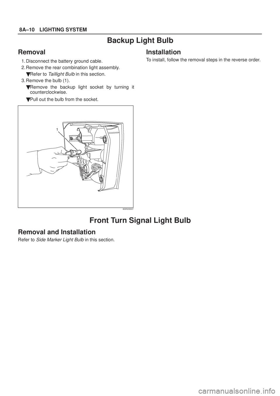
Backup Light Bulb
Removal
1. Disconnect the battery ground cable.
2. Remove the rear combination light assembly.
�Refer to
Taillight Bulb in this section.
3. Remove the bulb (1).
�Remove the backup light socket by turning it
counterclockwise.
�Pull out the bulb from the socket.
803R200007
Installation
To install, follow the removal steps in the reverse order.
Front Turn Signal Light Bulb
Removal and Installation
Refer to Side Marker Light Bulb in this section.
Page 1787 of 2100
LIGHTING SYSTEM8A±11
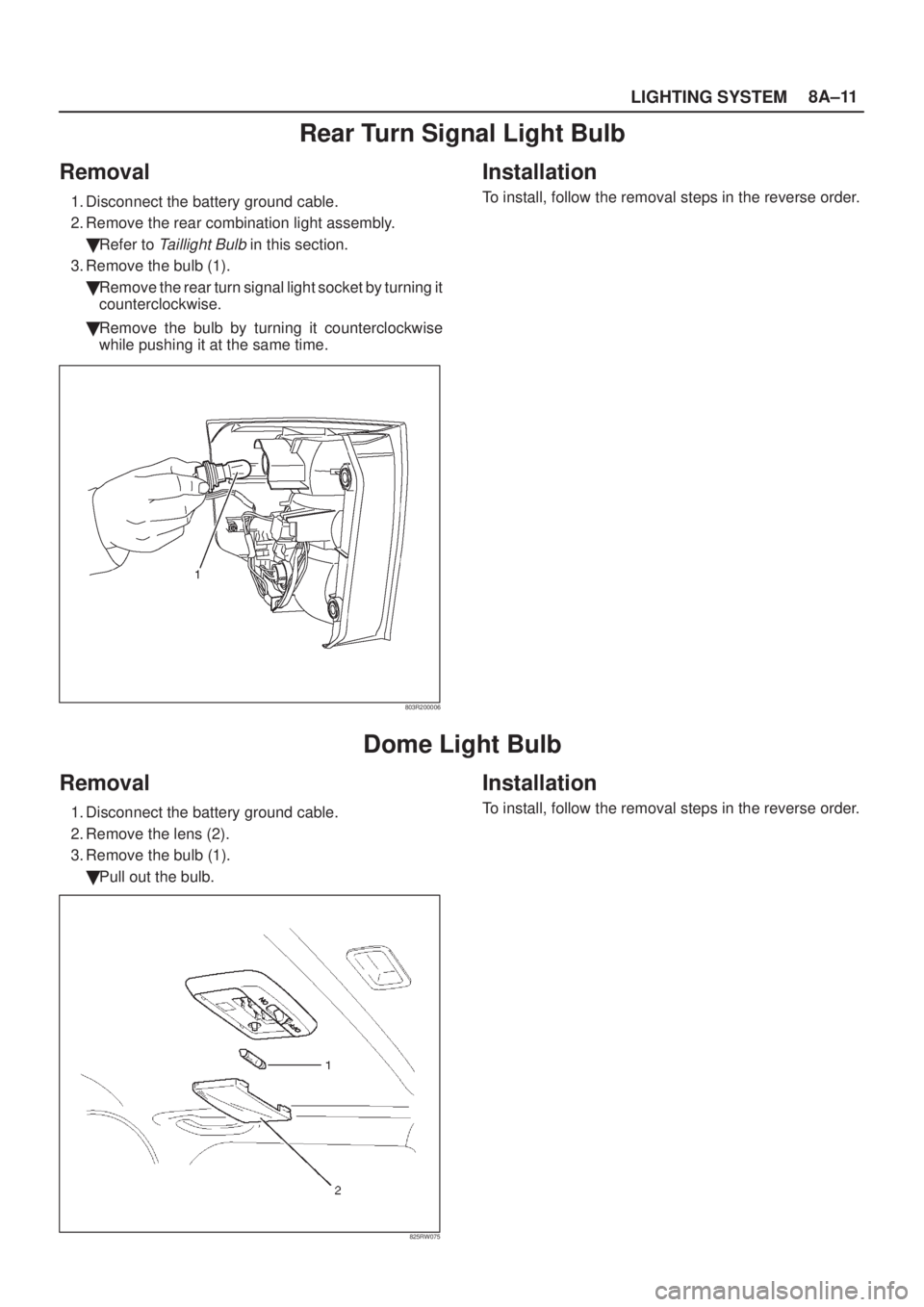
Rear Turn Signal Light Bulb
Removal
1. Disconnect the battery ground cable.
2. Remove the rear combination light assembly.
�Refer to
Taillight Bulb in this section.
3. Remove the bulb (1).
�Remove the rear turn signal light socket by turning it
counterclockwise.
�Remove the bulb by turning it counterclockwise
while pushing it at the same time.
803R200006
Installation
To install, follow the removal steps in the reverse order.
Dome Light Bulb
Removal
1. Disconnect the battery ground cable.
2. Remove the lens (2).
3. Remove the bulb (1).
�Pull out the bulb.
825RW075
Installation
To install, follow the removal steps in the reverse order.
Page 1796 of 2100
8A±20LIGHTING SYSTEM
Stoplight Switch
Removal and Installation
Refer to Stoplight Switch in Brake section.
Turn Signal Light Switch (Combination Switch)
Removal and Installation
Refer to Combination Switch in Steering section.
Illumination Controller
Removal
1. Disconnect the battery ground cable.
2. Remove the meter cluster panel cover assembly (2).
�Refer to
Instrument Panel Assembly in Body
Structure
section.
3. Remove the illumination controller (1).
�Disconnect the controller connector.
�Remove the controller knob (4).
�Remove the nut (3).
�Remove the controller from the back side of the
meter cluster panel assembly.
825R200027
Installation
To install, follow the removal steps in the reverse order.
Page 1797 of 2100
LIGHTING SYSTEM8A±21
Main Data and Specifications
Light and Bulb Specifications
801R200020
Legend
(1) High Mounted Stoplight
(2) Luggage Room Light
(3) Vanity Mirror Illumination Light
(4) Map Light
(5) Dome Light
(6) Meter(7) Front Turn Signal Light/Front Side Marker
Light/Parking Light
(8) Headlight
(9) Courtesy Light
(10) Taillight/Stoplight
(11) Backup Light
(12) Rear Turn Signal Light
(13) License Plate Light
Page 1798 of 2100

8A±22LIGHTING SYSTEM
Light NameBulb No.Rated
PowerNumber of
BulbsLens ColorRemarks
Headlight9005/900660w/51w2WhiteHalogen
Front Turn signal Light/
Front Side Marker Light/Parking Light1157NA27w/8w2Amber
Rear Turn Signal Light744021w2Amber
Backup Light92118w2White
Taillight/Stoplight744321w/5w2Red
High Mounted Stoplight92118w2Red
License Plate Light (Tailgate type)1685w2White
Map LightÐ8w2White
Dome LightÐ10w1White
Luggage Room LightÐ5w1White
Courtesy LightÐ3.4w4White
Check TransÐ1.4w1RedMeter
A/T Oil TempÐ1.4w1RedMeter
Cruise SetÐ1.4w1GreenMeter
Power DriveÐ1.4w1AmberMeter
Winter DriveÐ1.4w1GreenMeter
Turn SignalÐ1.4w2GreenMeter
Check TODÐ1.4w1RedMeter
High BeamÐ1.4w1BlueMeter
ABSÐ1.4w1AmberMeter
Seat BeltÐ2w1RedMeter
Indicator/Warning
Malfunction Indicator
(Check Engine)Ð1.4w1AmberMeter
Indicator/Warning
LightLow FuelÐ1.4w1AmberMeterg
Reduced PowerÐ1.4w1AmberMeter
Sports ModeÐ1.4w1GreenMeter
TOD FrontÐ1.1w1GreenMeter
TOD AutoÐ1.1w1GreenMeter
TOD RearÐ1.1w1GreenMeter
Oil PressureÐ1.4w1RedMeter
Brake SystemÐ1.4w1RedMeter
ChargeÐ1.4w1RedMeter
A/T Shift PositionÐ1.1w7
P,N,D,3,2,L
:Green
R: Amber
Meter
Air BagÐ2w1RedMeter
Illumination LightMeterÐ3.4w4Meter
Shift leverÐ1.4w1WhiteShift lever
Vanity MirrorÐ2w2WhiteSun Visor
Cigarette LighterÐ1.4w1WhiteCigarette
Lighter
AshtrayÐ1.4w1WhiteAshtray
Page 1821 of 2100
.
�Refer to
MID (1) in this section.
�Remove the control unit (3) from the bracke")
ENTERTAINMENT8C±9
MID Control Unit
Removal
1. Disconnect the battery ground cable.
2. Remove the MID control unit (3).
�Refer to
MID (1) in this section.
�Remove the control unit (3) from the bracket (2).
CAUTION: When the battery is disconnected, the
MID control unit directional data is lost (the control
unit returns to its start-up condition). When the
battery is reconnected, the display will be erroneous
until the control unit receives a clear GPS satellite
signal and resets its directional data.
After reconnecting the battery, wait until the satellite
mark indicator turns on. Select an area where there
are no high buildings or other obstacles to electro-
magnetic waves. Drive the vehicle in a straight line at
a speed exceeding 32 km/h (20 mph) for at least 20 se-
conds.
D08R200055
Installation
To install, follow the removal steps in the reverse order.
CAUTION: When installing the MID control unit,
turn the face with part number (4) stamped on the
MID control unit toward the front of vehicle.
Page 1833 of 2100

ENTERTAINMENT8C±21
Other Trouble Symptom
ConditionPossible causeCorrection
Elapsed time does not displayAn open circuit between GPS
receiver and MID control unit.Repair an open circuit.
Fuel consumption does not displayMID control unit and/or DISPLAY
not functioning.Replace the MID control unit and/or
DISPLAY.
Possible turning distance does not
changeAn open circuit between MID control
unit No.I-13±6 terminal and PCM
No.E35±48 terminal.Repair an open circuit.
Average fuel consumption does not
displayAn open circuit between MID control
unit No.I-13±5 terminal and PCM
No.E35±8 or MID control unit
NO.I-13±15 terminal and vehicle
speed sensor terminal No.E43±3.Repair an open circuit.
Current fuel consumption does not
displayRefer to average fuel consumption
items.Repair an open circuit.
Compass does not changeAn open circuit between MID control
unit and GPS receiver or insufficient
signal output of gyro sensor.Repair an open circuit and/or replace
gyro sensor.
CALENDER does not displayMID control unit and/or display not
functioning.Replace the MID control unit and/or
DISPLAY.
SERVICE does not changeAn open circuit of the vehicle speed
sensor.Repair an open circuit.
Units cannot be changedMID not functioning.Replace the MID control unit.

Removal and Installation
Refer to Combination")
 High Mounted Stoplight
(2) Luggage Room Light
(3) Vanity Mirror Illumination Light
(4) Map Light")