Page 2069 of 2100
9J1±19
RESTRAINT CONTROL SYSTEM
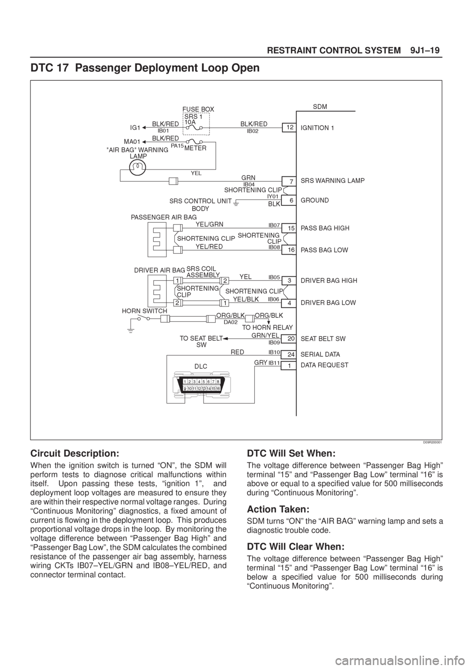
DTC 17 Passenger Deployment Loop Open
D09R200001
Circuit Description:
When the ignition switch is turned ªONº, the SDM will
perform tests to diagnose critical malfunctions within
itself. Upon passing these tests, ªignition 1º, and
deployment loop voltages are measured to ensure they
are within their respective normal voltage ranges. During
ªContinuous Monitoringº diagnostics, a fixed amount of
current is flowing in the deployment loop. This produces
proportional voltage drops in the loop. By monitoring the
voltage difference between ªPassenger Bag Highº and
ªPassenger Bag Lowº, the SDM calculates the combined
resistance of the passenger air bag assembly, harness
wiring CKTs IB07±YEL/GRN and IB08±YEL/RED, and
connector terminal contact.
DTC Will Set When:
The voltage difference between ªPassenger Bag Highº
terminal ª15º and ªPassenger Bag Lowº terminal ª16º is
above or equal to a specified value for 500 milliseconds
during ªContinuous Monitoringº.
Action Taken:
SDM turns ªONº the ªAIR BAGº warning lamp and sets a
diagnostic trouble code.
DTC Will Clear When:
The voltage difference between ªPassenger Bag Highº
terminal ª15º and ªPassenger Bag Lowº terminal ª16º is
below a specified value for 500 milliseconds during
ªContinuous Monitoringº.
Page 2071 of 2100
9J1±21
RESTRAINT CONTROL SYSTEM
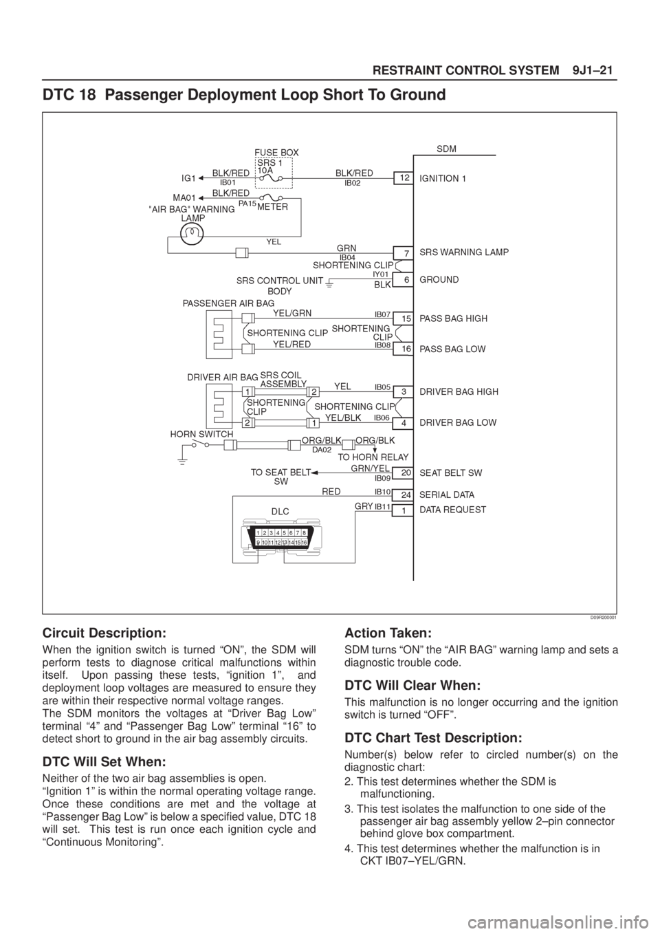
DTC 18 Passenger Deployment Loop Short To Ground
D09R200001
Circuit Description:
When the ignition switch is turned ªONº, the SDM will
perform tests to diagnose critical malfunctions within
itself. Upon passing these tests, ªignition 1º, and
deployment loop voltages are measured to ensure they
are within their respective normal voltage ranges.
The SDM monitors the voltages at ªDriver Bag Lowº
terminal ª4º and ªPassenger Bag Lowº terminal ª16º to
detect short to ground in the air bag assembly circuits.
DTC Will Set When:
Neither of the two air bag assemblies is open.
ªIgnition 1º is within the normal operating voltage range.
Once these conditions are met and the voltage at
ªPassenger Bag Lowº is below a specified value, DTC 18
will set. This test is run once each ignition cycle and
ªContinuous Monitoringº.
Action Taken:
SDM turns ªONº the ªAIR BAGº warning lamp and sets a
diagnostic trouble code.
DTC Will Clear When:
This malfunction is no longer occurring and the ignition
switch is turned ªOFFº.
DTC Chart Test Description:
Number(s) below refer to circled number(s) on the
diagnostic chart:
2. This test determines whether the SDM is
malfunctioning.
3. This test isolates the malfunction to one side of the
passenger air bag assembly yellow 2±pin connector
behind glove box compartment.
4. This test determines whether the malfunction is in
CKT IB07±YEL/GRN.
Page 2073 of 2100
9J1±23
RESTRAINT CONTROL SYSTEM
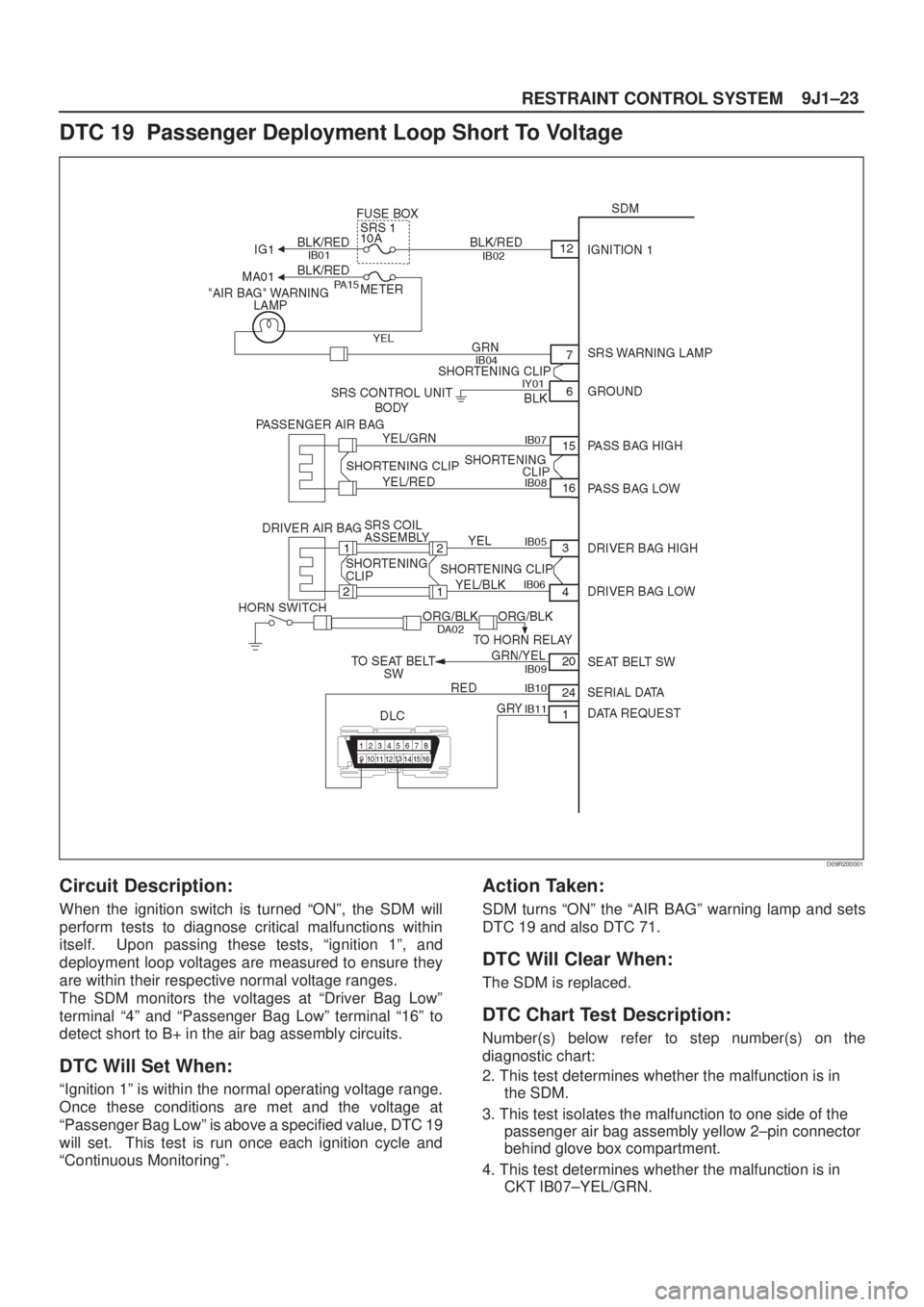
DTC 19 Passenger Deployment Loop Short To Voltage
D09R200001
Circuit Description:
When the ignition switch is turned ªONº, the SDM will
perform tests to diagnose critical malfunctions within
itself. Upon passing these tests, ªignition 1º, and
deployment loop voltages are measured to ensure they
are within their respective normal voltage ranges.
The SDM monitors the voltages at ªDriver Bag Lowº
terminal ª4º and ªPassenger Bag Lowº terminal ª16º to
detect short to B+ in the air bag assembly circuits.
DTC Will Set When:
ªIgnition 1º is within the normal operating voltage range.
Once these conditions are met and the voltage at
ªPassenger Bag Lowº is above a specified value, DTC 19
will set. This test is run once each ignition cycle and
ªContinuous Monitoringº.
Action Taken:
SDM turns ªONº the ªAIR BAGº warning lamp and sets
DTC 19 and also DTC 71.
DTC Will Clear When:
The SDM is replaced.
DTC Chart Test Description:
Number(s) below refer to step number(s) on the
diagnostic chart:
2. This test determines whether the malfunction is in
the SDM.
3. This test isolates the malfunction to one side of the
passenger air bag assembly yellow 2±pin connector
behind glove box compartment.
4. This test determines whether the malfunction is in
CKT IB07±YEL/GRN.
Page 2075 of 2100
9J1±25
RESTRAINT CONTROL SYSTEM
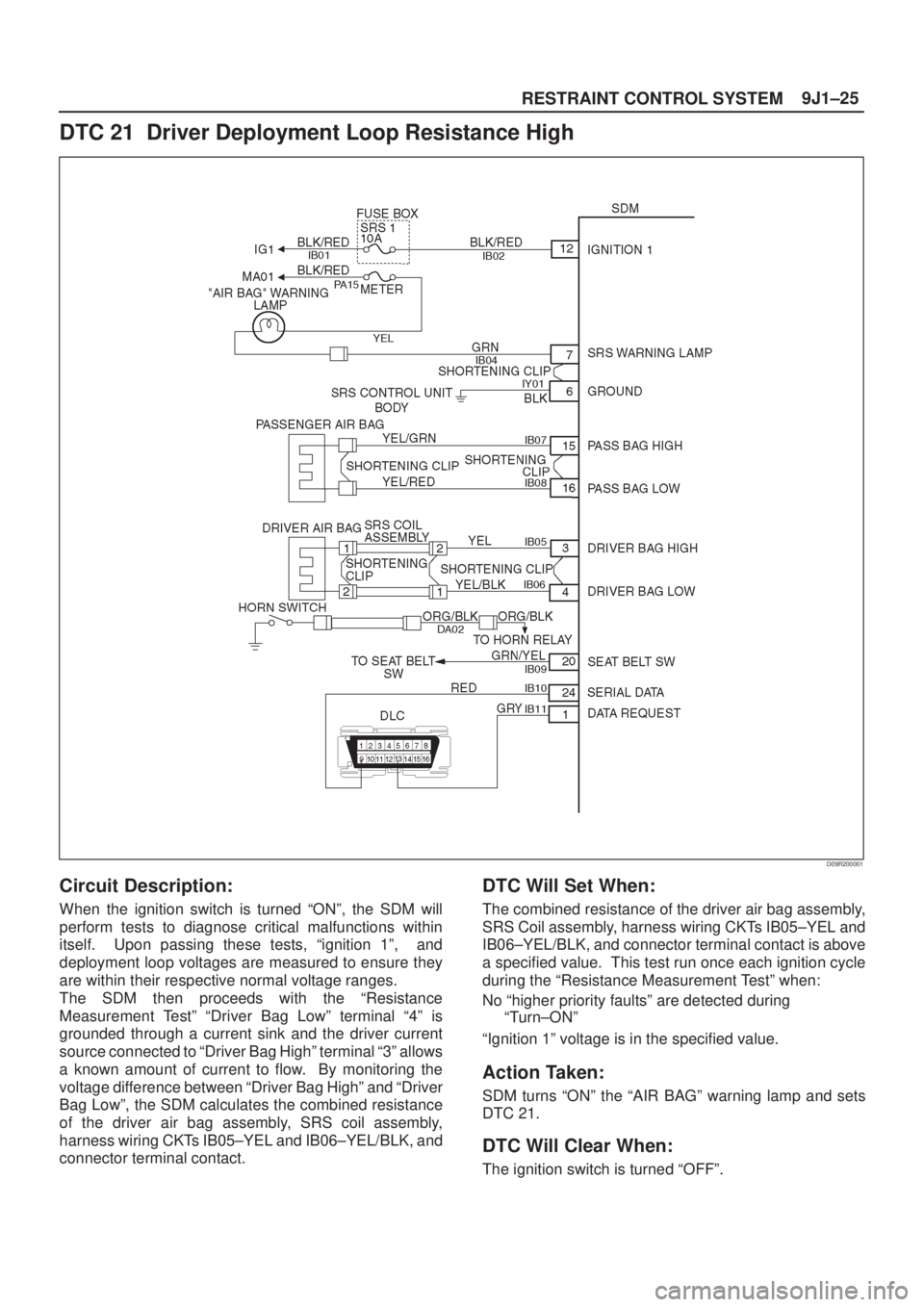
DTC 21 Driver Deployment Loop Resistance High
D09R200001
Circuit Description:
When the ignition switch is turned ªONº, the SDM will
perform tests to diagnose critical malfunctions within
itself. Upon passing these tests, ªignition 1º, and
deployment loop voltages are measured to ensure they
are within their respective normal voltage ranges.
The SDM then proceeds with the ªResistance
Measurement Testº ªDriver Bag Lowº terminal ª4º is
grounded through a current sink and the driver current
source connected to ªDriver Bag Highº terminal ª3º allows
a known amount of current to flow. By monitoring the
voltage difference between ªDriver Bag Highº and ªDriver
Bag Lowº, the SDM calculates the combined resistance
of the driver air bag assembly, SRS coil assembly,
harness wiring CKTs IB05±YEL and IB06±YEL/BLK, and
connector terminal contact.
DTC Will Set When:
The combined resistance of the driver air bag assembly,
SRS Coil assembly, harness wiring CKTs IB05±YEL and
IB06±YEL/BLK, and connector terminal contact is above
a specified value. This test run once each ignition cycle
during the ªResistance Measurement Testº when:
No ªhigher priority faultsº are detected during
ªTurn±ONº
ªIgnition 1º voltage is in the specified value.
Action Taken:
SDM turns ªONº the ªAIR BAGº warning lamp and sets
DTC 21.
DTC Will Clear When:
The ignition switch is turned ªOFFº.
Page 2076 of 2100
RESTRAINT CONTROL SYSTEM 9J1±26
DTC Chart Test Description:
Number(s) below refer to step number(s) on the
diagnostic chart:
2. This test determines whether the malfunction is in
the SDM.
3. This test verifies proper connection of the yellow
2±pin connector at the base of the steering column.
4. This test checks for proper contact and/or corrosion
of the 2±pin connector terminals at the base of
steering column.
5. This test isolate the malfunction to one side of the
SRS coil assembly yellow 2±pin connector located
at the base of the steering column.
6. This test determines whether the malfunction is due
to high resistance in the wiring.
7. This test determines whether the malfunction is in
the SRS coil assembly or the driver air bag
assembly.
Diagnostic Aids:
An intermittent condition is likely to be caused by a poor
connection at terminals ª1º and ª2º of the SRS coil 2±pin
connector at the base of the steering column, terminal ª1º
and ª2º of the driver air bag assembly 2±pin connector at
the top of the steering column, SDM terminals ª3º and ª4º
or a poor wire to terminal connection in CKT IB05±YEL or
IB06±YEL/BLK. The test for this diagnostic trouble code
is only run while the ªAIR BAGº warning lamp is
performing the bulb check, unless DTC 17 or DTC 26 is
detected. When a scan tool ªClear Codesº command is
issued and the malfunction is still present, the DTC will not
reappear until the next ignition cycle.
Page 2078 of 2100
RESTRAINT CONTROL SYSTEM 9J1±28
DTC 22 Driver Deployment Loop Resistance Low
D09R200001
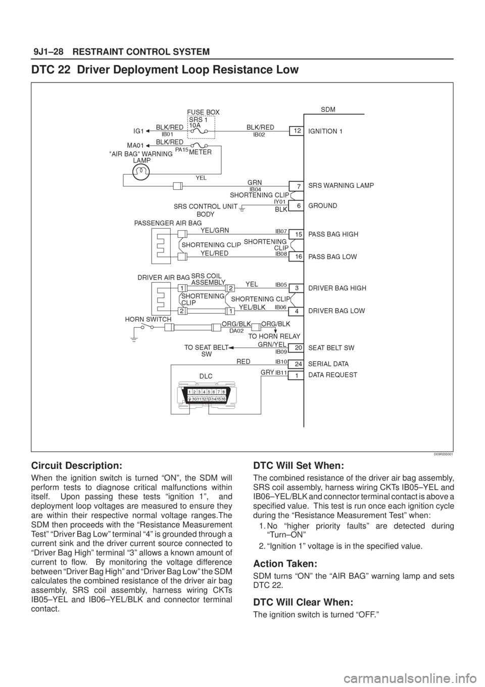
Circuit Description:
When the ignition switch is turned ªONº, the SDM will
perform tests to diagnose critical malfunctions within
itself. Upon passing these tests ªignition 1º, and
deployment loop voltages are measured to ensure they
are within their respective normal voltage ranges.The
SDM then proceeds with the ªResistance Measurement
Testº ªDriver Bag Lowº terminal ª4º is grounded through a
current sink and the driver current source connected to
ªDriver Bag Highº terminal ª3º allows a known amount of
current to flow. By monitoring the voltage difference
between ªDriver Bag Highº and ªDriver Bag Lowº the SDM
calculates the combined resistance of the driver air bag
assembly, SRS coil assembly, harness wiring CKTs
IB05±YEL and IB06±YEL/BLK and connector terminal
contact.
DTC Will Set When:
The combined resistance of the driver air bag assembly,
SRS coil assembly, harness wiring CKTs IB05±YEL and
IB06±YEL/BLK and connector terminal contact is above a
specified value. This test is run once each ignition cycle
during the ªResistance Measurement Testº when:
1. No ªhigher priority faultsº are detected during
ªTurn±ONº
2. ªIgnition 1º voltage is in the specified value.
Action Taken:
SDM turns ªONº the ªAIR BAGº warning lamp and sets
DTC 22.
DTC Will Clear When:
The ignition switch is turned ªOFF.º
Page 2079 of 2100
9J1±29
RESTRAINT CONTROL SYSTEM
DTC Chart Test Description:
Number(s) below refer to step number(s) on the
diagnostic chart:
2. This test determines whether the malfunction is in
the SDM.
3. This test verifies proper connection of the yellow
2±pin connector at the base of the steering column.
4. This test checks for proper operation of the shorting
clip in the yellow 2±pin connector.
5. This test isolate the malfunction to one side of the
SRS coil assembly yellow 2±pin connector located
at the base of steering column.
6. This test determines whether the malfunction is due
to shorting in the wiring.
7. This test determines whether the malfunction is in
the SRS coil assembly or the driver air bag
assembly.
Diagnostic Aids:
An intermittent condition is likely to be caused by a short
between CKT IB05±YEL or IB06±YEL/BLK or a
malfunctioning shorting clip on the driver air bag
assembly or SRS coil assembly which would require
replacement of the component. The test for this
diagnostic trouble code is only run while the ªAIR BAGº
warning lamp is performing the bulb check, unless DTC
17 or DTC 26 is detected. When a scan tool ªClear
Codesº command is issued and the malfunction is still
present, the DTC will not reappear until the next ignition
cycle.
Page 2081 of 2100
9J1±31
RESTRAINT CONTROL SYSTEM
DTC 24 Driver Deployment Loop Short To Ground
D09R200001
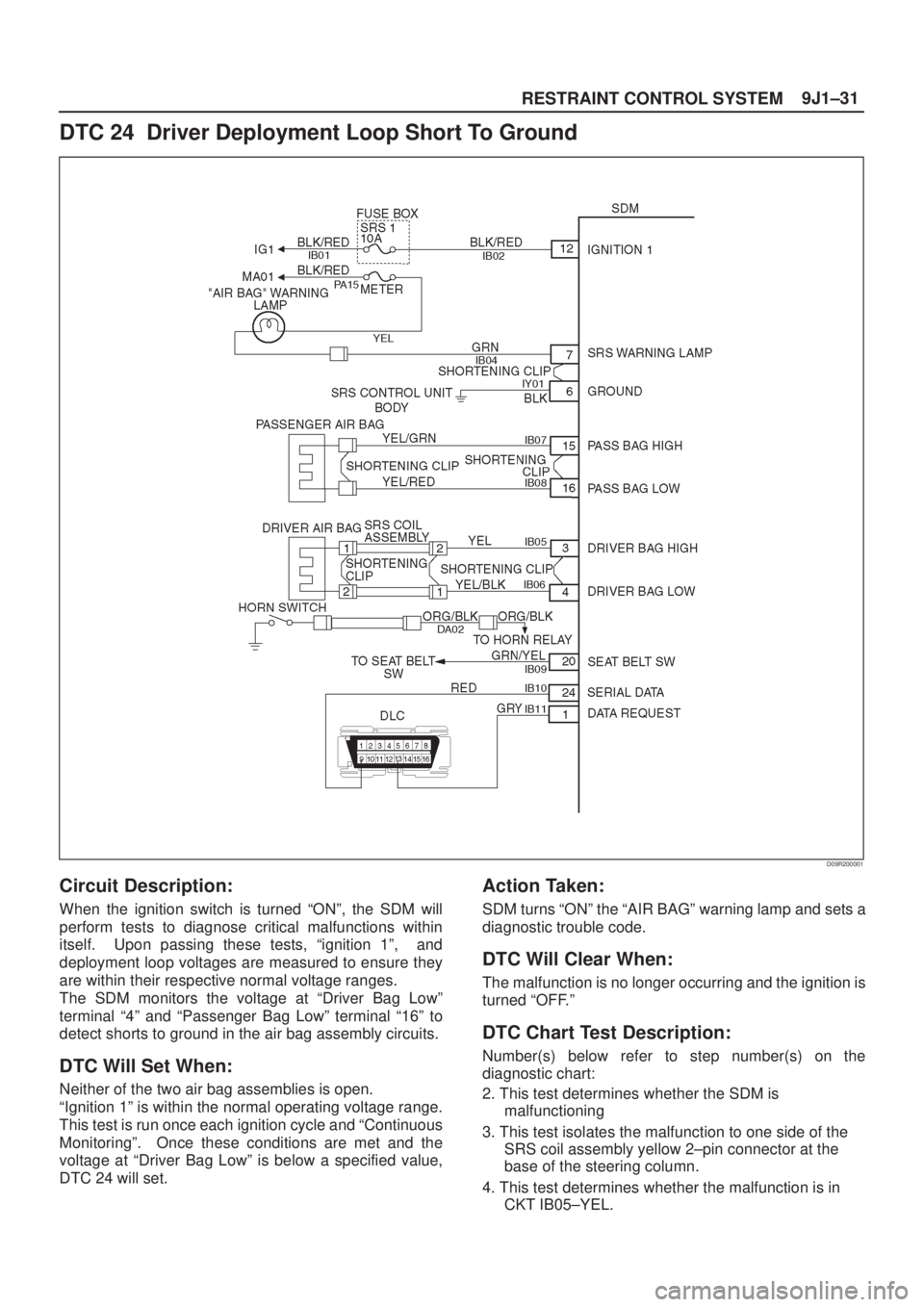
Circuit Description:
When the ignition switch is turned ªONº, the SDM will
perform tests to diagnose critical malfunctions within
itself. Upon passing these tests, ªignition 1º, and
deployment loop voltages are measured to ensure they
are within their respective normal voltage ranges.
The SDM monitors the voltage at ªDriver Bag Lowº
terminal ª4º and ªPassenger Bag Lowº terminal ª16º to
detect shorts to ground in the air bag assembly circuits.
DTC Will Set When:
Neither of the two air bag assemblies is open.
ªIgnition 1º is within the normal operating voltage range.
This test is run once each ignition cycle and ªContinuous
Monitoringº. Once these conditions are met and the
voltage at ªDriver Bag Lowº is below a specified value,
DTC 24 will set.
Action Taken:
SDM turns ªONº the ªAIR BAGº warning lamp and sets a
diagnostic trouble code.
DTC Will Clear When:
The malfunction is no longer occurring and the ignition is
turned ªOFF.º
DTC Chart Test Description:
Number(s) below refer to step number(s) on the
diagnostic chart:
2. This test determines whether the SDM is
malfunctioning
3. This test isolates the malfunction to one side of the
SRS coil assembly yellow 2±pin connector at the
base of the steering column.
4. This test determines whether the malfunction is in
CKT IB05±YEL.