Page 2059 of 2100
9J1±9
RESTRAINT CONTROL SYSTEM
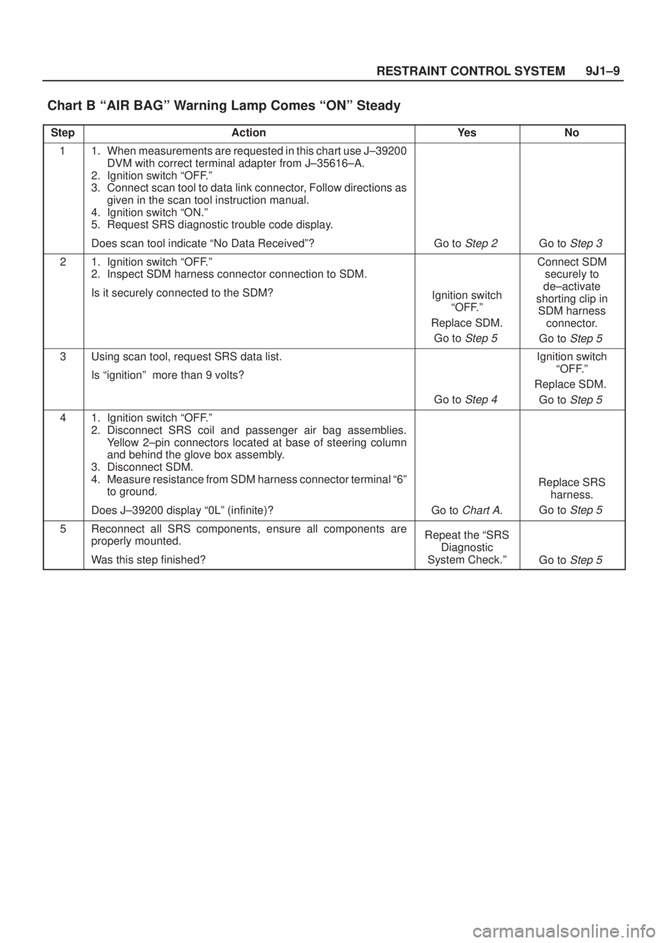
Chart B ªAIR BAGº Warning Lamp Comes ªONº Steady
StepActionYe sNo
11. When measurements are requested in this chart use J±39200
DVM with correct terminal adapter from J±35616±A.
2. Ignition switch ªOFF.º
3. Connect scan tool to data link connector, Follow directions as
given in the scan tool instruction manual.
4. Ignition switch ªON.º
5. Request SRS diagnostic trouble code display.
Does scan tool indicate ªNo Data Receivedº?
Go to Step 2 Go to Step 3
21. Ignition switch ªOFF.º
2. Inspect SDM harness connector connection to SDM.
Is it securely connected to the SDM?
Ignition switch
ªOFF.º
Replace SDM.
Go to
Step 5
Connect SDM
securely to
de±activate
shorting clip in
SDM harness
connector.
Go to
Step 5
3Using scan tool, request SRS data list.
Is ªignitionº more than 9 volts?
Go to Step 4
Ignition switch
ªOFF.º
Replace SDM.
Go to
Step 5
41. Ignition switch ªOFF.º
2. Disconnect SRS coil and passenger air bag assemblies.
Yellow 2±pin connectors located at base of steering column
and behind the glove box assembly.
3. Disconnect SDM.
4. Measure resistance from SDM harness connector terminal ª6º
to ground.
Does J±39200 display ª0Lº (infinite)?
Go to Chart A.
Replace SRS
harness.
Go to
Step 5
5Reconnect all SRS components, ensure all components are
properly mounted.
Was this step finished?Repeat the ªSRS
Diagnostic
System Check.º
Go to Step 5
Page 2060 of 2100
RESTRAINT CONTROL SYSTEM 9J1±10
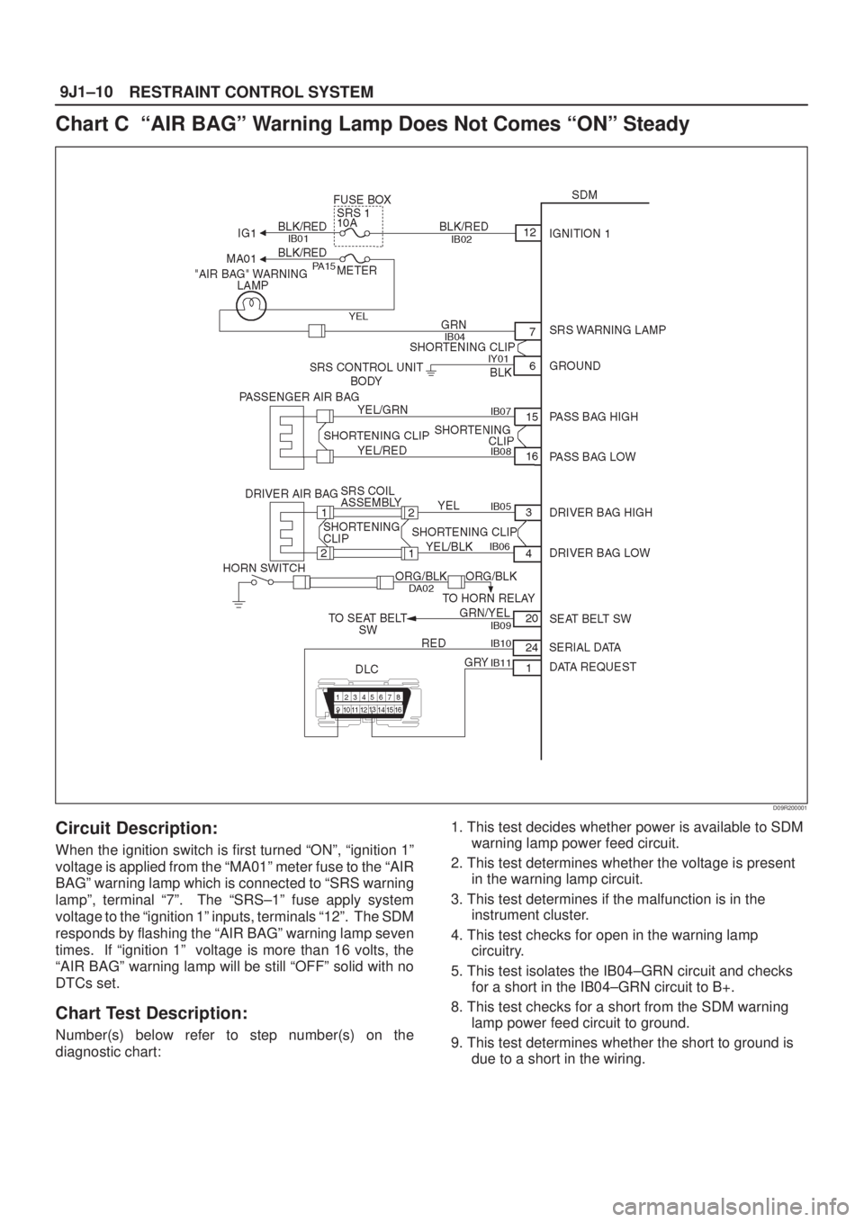
Chart C ªAIR BAGº Warning Lamp Does Not Comes ªONº Steady
D09R200001
Circuit Description:
When the ignition switch is first turned ªONº, ªignition 1º
voltage is applied from the ªMA01º meter fuse to the ªAIR
BAGº warning lamp which is connected to ªSRS warning
lampº, terminal ª7º. The ªSRS±1º fuse apply system
voltage to the ªignition 1º inputs, terminals ª12º. The SDM
responds by flashing the ªAIR BAGº warning lamp seven
times. If ªignition 1º voltage is more than 16 volts, the
ªAIR BAGº warning lamp will be still ªOFFº solid with no
DTCs set.
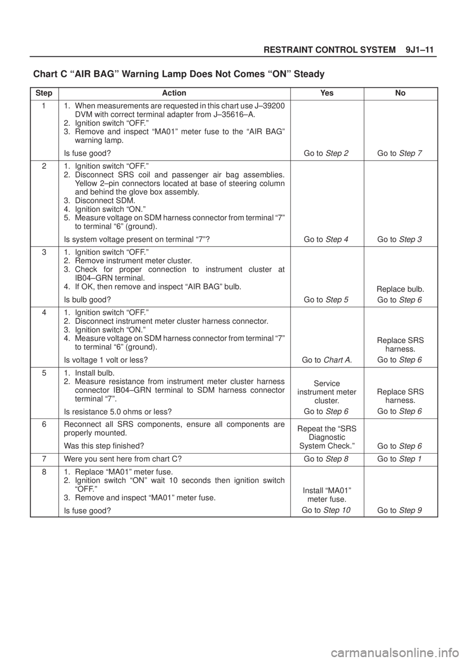
Chart Test Description:
Number(s) below refer to step number(s) on the
diagnostic chart:1. This test decides whether power is available to SDM
warning lamp power feed circuit.
2. This test determines whether the voltage is present
in the warning lamp circuit.
3. This test determines if the malfunction is in the
instrument cluster.
4. This test checks for open in the warning lamp
circuitry.
5. This test isolates the IB04±GRN circuit and checks
for a short in the IB04±GRN circuit to B+.
8. This test checks for a short from the SDM warning
lamp power feed circuit to ground.
9. This test determines whether the short to ground is
due to a short in the wiring.
Page 2061 of 2100
9J1±11
RESTRAINT CONTROL SYSTEM
Chart C ªAIR BAGº Warning Lamp Does Not Comes ªONº Steady
StepActionYe sNo
11. When measurements are requested in this chart use J±39200
DVM with correct terminal adapter from J±35616±A.
2. Ignition switch ªOFF.º
3. Remove and inspect ªMA01º meter fuse to the ªAIR BAGº
warning lamp.
Is fuse good?
Go to Step 2 Go to Step 7
21. Ignition switch ªOFF.º
2. Disconnect SRS coil and passenger air bag assemblies.
Yellow 2±pin connectors located at base of steering column
and behind the glove box assembly.
3. Disconnect SDM.
4. Ignition switch ªON.º
5. Measure voltage on SDM harness connector from terminal ª7º
to terminal ª6º (ground).
Is system voltage present on terminal ª7º?
Go to Step 4 Go to Step 3
31. Ignition switch ªOFF.º
2. Remove instrument meter cluster.
3. Check for proper connection to instrument cluster at
IB04±GRN terminal.
4. If OK, then remove and inspect ªAIR BAGº bulb.
Is bulb good?
Go to Step 5
Replace bulb.
Go to
Step 6
41. Ignition switch ªOFF.º
2. Disconnect instrument meter cluster harness connector.
3. Ignition switch ªON.º
4. Measure voltage on SDM harness connector from terminal ª7º
to terminal ª6º (ground).
Is voltage 1 volt or less?
Go to Chart A.
Replace SRS
harness.
Go to
Step 6
51. Install bulb.
2. Measure resistance from instrument meter cluster harness
connector IB04±GRN terminal to SDM harness connector
terminal ª7º.
Is resistance 5.0 ohms or less?
Service
instrument meter
cluster.
Go to
Step 6
Replace SRS
harness.
Go to
Step 6
6Reconnect all SRS components, ensure all components are
properly mounted.
Was this step finished?Repeat the ªSRS
Diagnostic
System Check.º
Go to Step 6
7Were you sent here from chart C?Go to Step 8 Go to Step 1
81. Replace ªMA01º meter fuse.
2. Ignition switch ªONº wait 10 seconds then ignition switch
ªOFF.º
3. Remove and inspect ªMA01º meter fuse.
Is fuse good?
Install ªMA01º
meter fuse.
Go to
Step 10 Go to Step 9
Page 2062 of 2100
RESTRAINT CONTROL SYSTEM 9J1±12
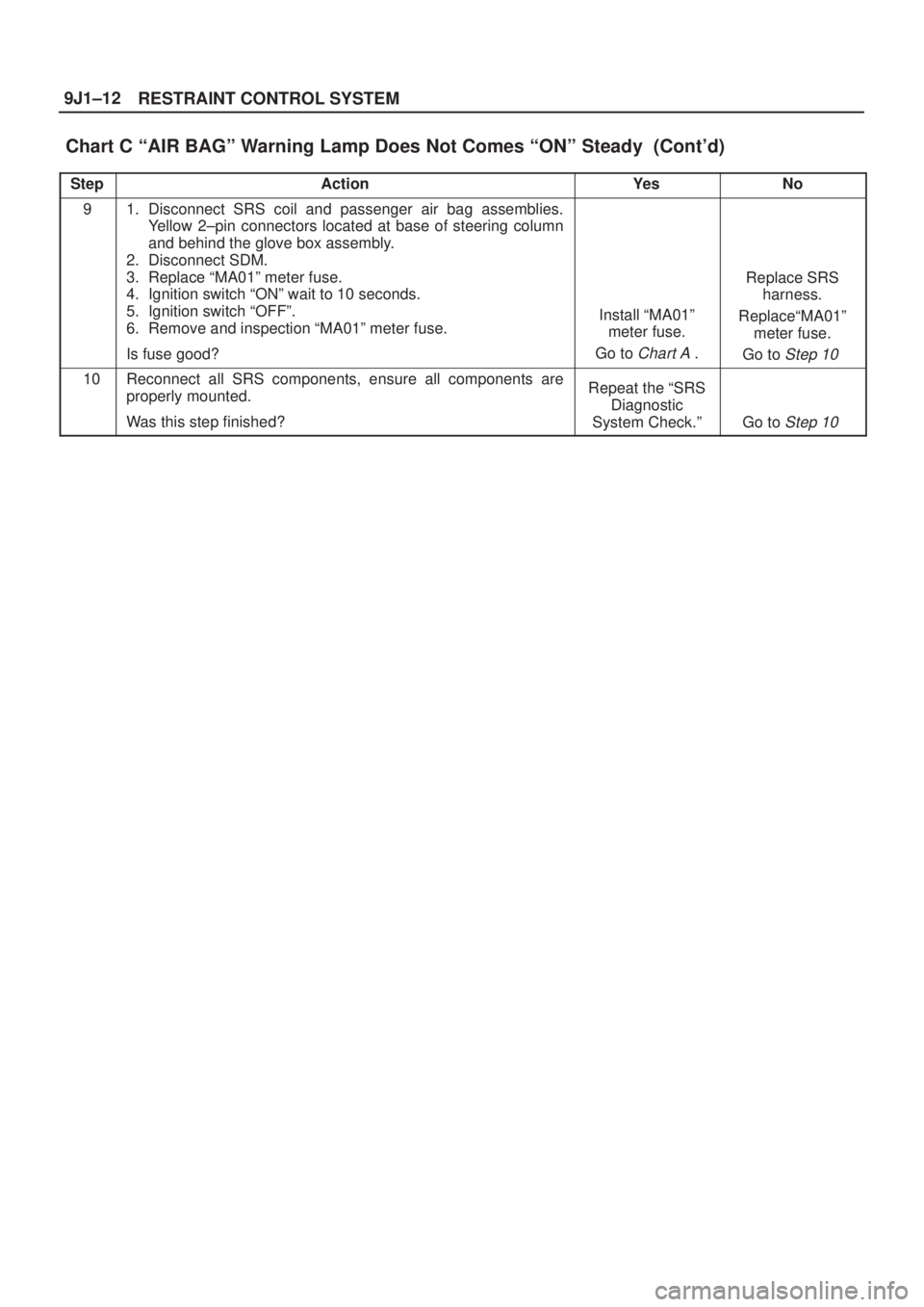
Chart C ªAIR BAGº Warning Lamp Does Not Comes ªONº Steady (Cont'd)
StepNo Ye s Action
91. Disconnect SRS coil and passenger air bag assemblies.
Yellow 2±pin connectors located at base of steering column
and behind the glove box assembly.
2. Disconnect SDM.
3. Replace ªMA01º meter fuse.
4. Ignition switch ªONº wait to 10 seconds.
5. Ignition switch ªOFFº.
6. Remove and inspection ªMA01º meter fuse.
Is fuse good?
Install ªMA01º
meter fuse.
Go to
Chart A .
Replace SRS
harness.
ReplaceªMA01º
meter fuse.
Go to
Step 10
10Reconnect all SRS components, ensure all components are
properly mounted.
Was this step finished?Repeat the ªSRS
Diagnostic
System Check.º
Go to Step 10
Page 2063 of 2100
9J1±13
RESTRAINT CONTROL SYSTEM
DTC 15 Passenger Deployment Loop Resistance High
D09R200001
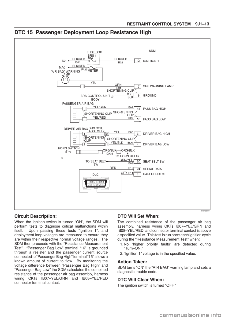
Circuit Description:
When the ignition switch is turned ªONº, the SDM will
perform tests to diagnose critical malfunctions within
itself. Upon passing these tests ªignition 1º, and
deployment loop voltages are measured to ensure they
are within their respective normal voltage ranges. The
SDM then proceeds with the ªResistance Measurement
Testº. ªPassenger Bag Lowº terminal ª16º is grounded
through a resister and the passenger current source
connected to ªPassenger Bag Highº terminal ª15º allows a
known amount of current to flow. By monitoring the
voltage difference between ªPassenger Bag Highº and
ªPassenger Bag Lowº the SDM calculates the combined
resistance of the passenger air bag assembly, harness
wiring CKTs IB07±YEL/GRN and IB08±YEL/RED
connector terminal contact.
DTC Will Set When:
The combined resistance of the passenger air bag
assembly, harness wiring CKTs IB07±YEL/GRN and
IB08±YEL/RED, and connector terminal contact is above
a specified value. This test is run once each ignition cycle
during the ªResistance Measurement Testº when:
1. No ªhigher priority faultsº are detected during
ªTurn±ON.º
2. ªIgnition 1º voltage is in the specified value.
Action Taken:
SDM turns ªONº the ªAIR BAGº warning lamp and sets a
diagnostic trouble code.
DTC Will Clear When:
The ignition switch is turned ªOFF.º
Page 2064 of 2100
RESTRAINT CONTROL SYSTEM 9J1±14
DTC Chart Test Description:
Number(s) below refer to step number(s) on the
diagnostic chart:
2. This test determines whether the malfunction is in
the SDM.
3. This test verifies proper connection of the yellow
2±pin connector.
4. This test checks for proper contact and/or corrosion
of the yellow 2±pin connector terminals.
5. The test checks for a malfunctioning passenger air
bag assembly.
6. This test determines whether the malfunction is due
to high resistance in the wiring.
Diagnostic Aids:
An intermittent condition is likely to be caused by a poor
connection at the passenger air bag assembly harness
connector terminals ª1º and ª2º, SDM terminal ª15º and
ª16º, or a poor wire to terminal connection in CKTs
IB07±YEL/GRN and IB08±YEL/RED. This test for this
diagnostic trouble code is only run while the ªAIR BAGº
warning lamp is performing the bulb check, unless DTC
17 or DTC 26 is detected. When a scan tool ªClear
Codesº command is issued and the malfunction is still
present, the DTC will not reappear until the next ignition
cycle.
Page 2066 of 2100
RESTRAINT CONTROL SYSTEM 9J1±16
DTC 16 Passenger Deployment Loop Resistance Low
D09R200001
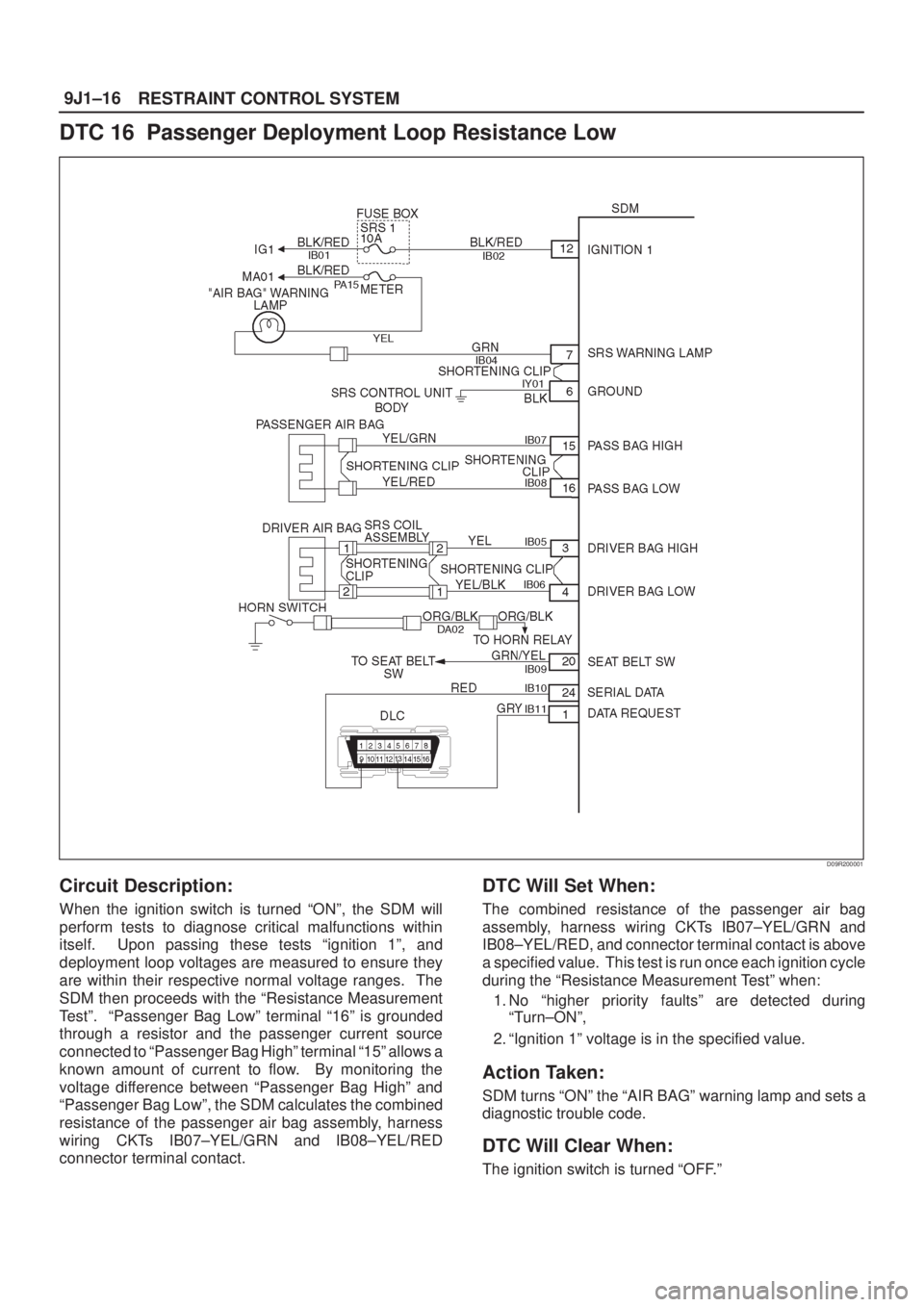
Circuit Description:
When the ignition switch is turned ªONº, the SDM will
perform tests to diagnose critical malfunctions within
itself. Upon passing these tests ªignition 1º, and
deployment loop voltages are measured to ensure they
are within their respective normal voltage ranges. The
SDM then proceeds with the ªResistance Measurement
Testº. ªPassenger Bag Lowº terminal ª16º is grounded
through a resistor and the passenger current source
connected to ªPassenger Bag Highº terminal ª15º allows a
known amount of current to flow. By monitoring the
voltage difference between ªPassenger Bag Highº and
ªPassenger Bag Lowº, the SDM calculates the combined
resistance of the passenger air bag assembly, harness
wiring CKTs IB07±YEL/GRN and IB08±YEL/RED
connector terminal contact.
DTC Will Set When:
The combined resistance of the passenger air bag
assembly, harness wiring CKTs IB07±YEL/GRN and
IB08±YEL/RED, and connector terminal contact is above
a specified value. This test is run once each ignition cycle
during the ªResistance Measurement Testº when:
1. No ªhigher priority faultsº are detected during
ªTurn±ONº,
2. ªIgnition 1º voltage is in the specified value.
Action Taken:
SDM turns ªONº the ªAIR BAGº warning lamp and sets a
diagnostic trouble code.
DTC Will Clear When:
The ignition switch is turned ªOFF.º
Page 2067 of 2100
9J1±17
RESTRAINT CONTROL SYSTEM
DTC Chart Test Description:
Number(s) below refer to step number(s) on the
diagnostic chart:
2. This test determines whether the malfunction is in
the SDM.
3. This test verifies connection of the yellow 2±pin
connector.
4. This test cheeks for proper operation of the shorting
clip in the yellow 2±pin connector.
5. The test checks for a malfunction passenger air bag
assembly.
6. This test determines whether the malfunctioning is
due to shorting in the wiring.
Diagnostic Aids:
An intermittent condition is likely to be caused by a short
between CKTs IB07±YEL/GRN and IB08±YEL/RED, or a
malfunctioning shorting clip on the passenger air bag
assembly which would require replacement of the air bag
assembly. The test for this diagnostic trouble code is only
run while ªAIR BAGº warning lamp is performing the bulb
check, unless DTC 17 or DTC 26 is detected. When a
scan tool ªClear Codesº command is issued and the
malfunction is still present, the DTC will not reappear until
the next ignition cycle.