Page 1944 of 2100
8G±6SEATS
19. Remove the seat belt buckle assembly.
20. Remove the trim cover and pad (Seat cushion side)
21. Remove the seat heater and connector (Seat cushion
side).
22. Remove the power seat harness.
Installation
To install, follow the removal steps in the reverse order,
noting the following points:
1. Tighten the reclining device fixing bolts to the
specified torque.
Torque: 46 N´m (34 lb ft)
2. Tighten the seat adjuster fixing bolts to the specified
torque.
Torque: 21 N´m (15 lb ft) to seat cushion
Torque: 39 N´m (29 lb ft) to body
3. Tighten the seat belt buckle assembly fixing bolts to
the specified torque.
Torque: 29 N´m (22 lb ft)
Page 1946 of 2100

8G±8SEATS
Removal
1. Remove the hinge covers.
2. Remove the seat cushion fixing bolts.
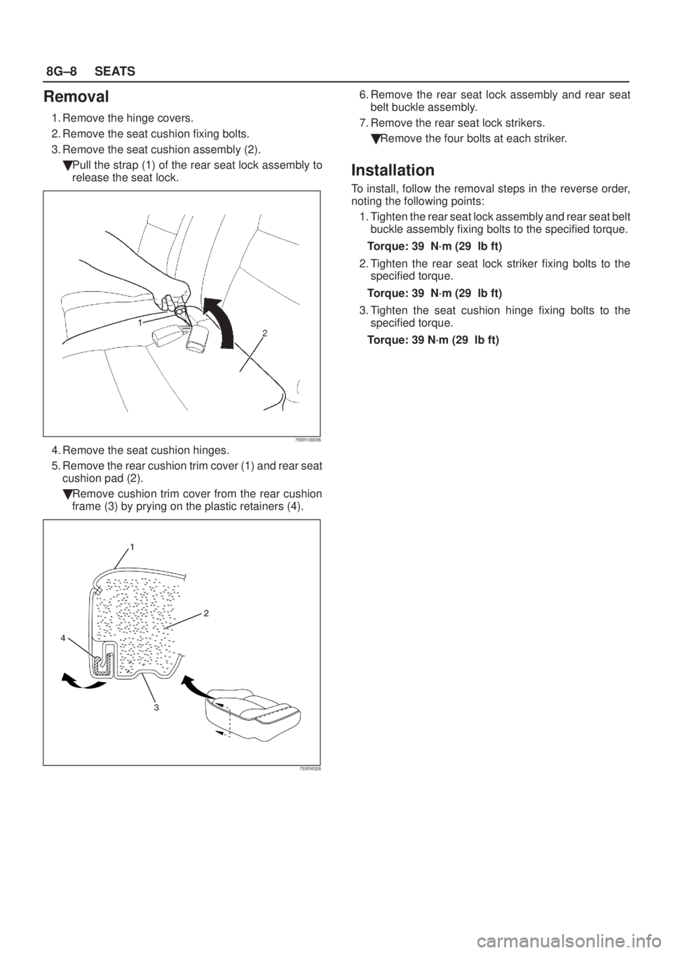
3. Remove the seat cushion assembly (2).
�Pull the strap (1) of the rear seat lock assembly to
release the seat lock.
755R100006
4. Remove the seat cushion hinges.
5. Remove the rear cushion trim cover (1) and rear seat
cushion pad (2).
�Remove cushion trim cover from the rear cushion
frame (3) by prying on the plastic retainers (4).
755RX028
6. Remove the rear seat lock assembly and rear seat
belt buckle assembly.
7. Remove the rear seat lock strikers.
�Remove the four bolts at each striker.
Installation
To install, follow the removal steps in the reverse order,
noting the following points:
1. Tighten the rear seat lock assembly and rear seat belt
buckle assembly fixing bolts to the specified torque.
Torque: 39 N´m (29 lb ft)
2. Tighten the rear seat lock striker fixing bolts to the
specified torque.
Torque: 39 N´m (29 lb ft)
3. Tighten the seat cushion hinge fixing bolts to the
specified torque.
Torque: 39 N´m (29 lb ft)
Page 1947 of 2100
SEATS8G±9
Rear Seat Back Assembly and Associated Parts
755R200005
Legend
(1) Headrest
(2) Seat Back Assembly
(3) Guide Holder
(4) Release Knob(5) Seat Lock Cover
(6) Seat Lock Striker
(7) Side Hinge
(8) Body Floor Panel
(9) Center Hinge
Removal
1. Pull the release knob and pull the seat back assembly
forward.
2. Remove the seat lock covers.
�Remove the three screws from each side.
3. Remove the luggage floor carpets.
�Pull the nine carpet fixing clips from the backside of
the seat back assembly.4. Remove the seat back assembly.
�Remove the four fixing bolts at each seat back.
5. Remove the headrests.
6. Remove the release knobs.
�Turn the knob counterclockwise to remove it.
7. Remove the trim covers.
8. Remove the guide holders.
9. Remove the side hinges.
�Remove the one fixing nut at each side hinge.
Page 1948 of 2100
8G±10SEATS
10. Remove the center hinge.
�Remove the two fixing bolts.
Installation
To install, follow the removal steps in the reverse order,
noting the following points:
1. Tighten the center hinge fixing bolts to the specified
torque.
Torque: 39 N´m (29 lb ft)
2. Tighten the side hinge fixing nuts to the specified
torque.
Torque: 29 N´m (22 lb ft)
3. Tighten the side lock striker fixing bolts to the
specified torque.
Torque: 19 N´m (14 lb ft)
Page 2009 of 2100
9A±8SEAT BELT SYSTEM
Rear Center Seat Belt / Buckle Assembly
Rear Center Seat Belt / Buckle Assembly and Associated Parts
755R200006
Legend
(1) Rear Seat Lock Assembly(2) Rear Seat Belt Buckle Assembly
(3) Rear Cushion Frame Assembly
Removal
1. Remove the rear cushion frame assembly.
�Refer to Rear Seat Assembly in Seats section.
2. Remove the rear seat lock assembly and rear seat
belt buckle assembly.
Installation
To install, follow the removal steps in the reverse order,
noting the following point.
1. Tighten the rear seat lock assembly and rear seat belt
buckle assembly fixing bolts to the specified torque.
Torque: 39 N´m (29 lb ft)
NOTE: Removal and installation procedure of rear center
seat belt assembly same as rear seat belt buckle
assembly procedures.
Page 2030 of 2100

SUPPLEMENTAL RESTRAINT SYSTEM 9J±16
WARNING: FAILURE TO FOLLOW PROPER SRS AIR
BAG ASSEMBLY DISPOSAL PROCEDURES CAN
RESULT IN AIR BAG DEPLOYMENT WHICH MAY
CAUSE PERSONAL INJURY. UNDEPLOYED AIR
BAG ASSEMBLIES MUST NOT BE DISPOSED OF
THROUGH NORMAL REFUSE CHANNELS. THE
UNDEPLOYED AIR BAG ASSEMBLY CONTAINS
SUBSTANCES THAT CAN CAUSE SEVERE ILLNESS
OR PERSONAL INJURY IF THE SEALED CONTAINER
IS DAMAGED DURING DISPOSAL. DISPOSAL IN
ANY MANNER INCONSISTENT WITH PROPER
PROCEDURES MAY BE A VIOLATION OF FEDERAL,
STATE AND/OR LOCAL LAWS.
1. Turn ignition switch to ªLOCKº, remove key and put
on safety glasses.
2. Remove all loose objects from front seats.
3. Disconnect SRS coil assembly, yellow 2±pin
connector located at the base of the steering column.
4. Cut the SRS coil assembly yellow 2±pin harness
connector from the vehicle leaving at least 16 cm (six
inches) of wire at the connector.
5. Strip 1/2 inch (13 mm) of insulation from yellow±green
and yellow±black wire lead of the connector.
6. Cut two 30 feet (900 cm) deployment wires from 18
gauge (0.8 mm�) or thicker multi±strand wire. These
wires will be used to fabricate the driver deployment
harness.
7. Strip 1/2 inch (13 mm) of insulation from both ends of
the wires cut in the previous step.
8. Short the wires by twisting together one end from
each. Deployment wires shall remain shorted and not
be connected to a power source until the air bag is to
be deployed.
WARNING: FAILURE TO FOLLOW PROCEDURES IN
THE ORDER LISTED COULD RESULT IN PERSONAL
INJURY. NEVER CONNECT DEPLOYMENT WIRES
TO ANY POWER SOURCE BEFORE CONNECTING
DEPLOYMENT WIRES TO THE AIR BAG ASSEMBLY
LEADS. DEPLOYMENT WIRES SHALL REMAIN
SHORTED AND NOT BE CONNECTED TO A POWER
SOURCE UNTIL THE AIR BAG IS TO BE DEPLOYED.
THE AIR BAG ASSEMBLY WILL IMMEDIATELY
DEPLOY THE AIR BAG WHEN A POWER SOURCE IS
CONNECTED TO IT. WEAR SAFETY GLASSES
THROUGHOUT THIS ENTIRE DEPLOYMENT AND
DISPOSAL PROCEDURE.
9. Twist together one connector wire lead to one
deployment wire. The connection should be
mechanically secure.
10. Bend twisted connection made in the previous step
flat and wrap tightly with electrical tape to insulate and
secure.
11. Twist together, bend and tape the remaining
connector wire lead to the remaining deployment
wire.
12. Connect the deployment harness to the driver air bag
assembly, yellow 2±pin connector at the base of the
steering column. Route deployment harness out the
driver side of the vehicle.WARNING: DEPLOYMENT WIRES SHALL REMAIN
SHORTED AND NOT BE CONNECTED TO A POWER
SOURCE UNTIL THE AIR BAG IS TO BE DEPLOYED.
THE AIR BAG ASSEMBLY WILL IMMEDIATELY
DEPLOY THE AIR BAG WHEN A POWER SOURCE IS
CONNECTED TO IT.
CONNECTING THE DEPLOYMENT WIRES TO THE
POWER SOURCE SHOULD ALWAYS BE THE FINAL
STEP IN THE AIR BAG ASSEMBLY DEPLOYMENT
PROCEDURE.
FAILURE TO FOLLOW PROCEDURES IN THE OR-
DER LISTED COULD RESULT IN PERSONAL INJURY.
13. Disconnect passenger air bag assembly, yellow 2±pin
connector located behind glove box assembly.
14. Cut the passenger air bag assembly harness
connector from the vehicle leaving at least six inches
(16 cm) of wire at the connector.
15. Strip 1/2 inch (13 mm) of insulation from yellow±green
and yellow±red wire lead of the connector.
16. Cut two 30 feet (900 cm) deployment wires from 18
gauge (0.8 mm�) or thicker multi±strand wire. These
wires will be used to fabricate the passenger
deployment harness.
17. Strip 1/2 inch (13 mm) of insulation from both ends of
the wires cut in the previous step.
18. Short the wires by twisting together one end from
each. Deployment wires shall remain shorted and not
be connected to a power source until the air bag is to
be deployed.
WARNING: FAILURE TO FOLLOW PROCEDURES IN
THE ORDER LISTED COULD RESULT IN PERSONAL
INJURY. NEVER CONNECT DEPLOYMENT WIRES
TO ANY POWER SOURCE BEFORE CONNECTING
DEPLOYMENT WIRES TO THE AIR BAG ASSEMBLY
LEADS. DEPLOYMENT WIRES SHALL REMAIN
SHORTED AND NOT BE CONNECTED TO A POWER
SOURCE UNTIL THE AIR BAG IS TO BE DEPLOYED.
THE AIR BAG ASSEMBLY WILL IMMEDIATELY
DEPLOY THE AIR BAG WHEN SAFETY GLASSES
THROUGHOUT THIS ENTIRE DEPLOYMENT AND
DISPOSAL PROCEDURE.
19. Twist together one connector wire lead to one
deployment wire. The connection should be
mechanically secure.
20. Bend twisted connection made in the previous step
flat and wrap tightly with electrical tape to insulate and
secure.
21. Twist together, bend and tape the remaining
connector wire lead to the remaining deployment
wire.
22. Connect the deployment harness to the passenger air
bag assembly, yellow 2±pin connector located behind
the glove box assembly. Route deployment harness
out the passenger side of the vehicle.
WARNING: DEPLOYMENT WIRES SHALL REMAIN
SHORTED AND NOT BE CONNECTED TO A POWER
SOURCE UNTIL THE AIR BAG IS TO BE DEPLOYED.
THE AIR BAG ASSEMBLY WILL IMMEDIATELY
DEPLOY THE AIR BAG WHEN A POWER SOURCE IS
CONNECTED TO IT. CONNECTING THE