Page 1663 of 2100
7A±79 AUTOMATIC TRANSMISSION (4L30±E)
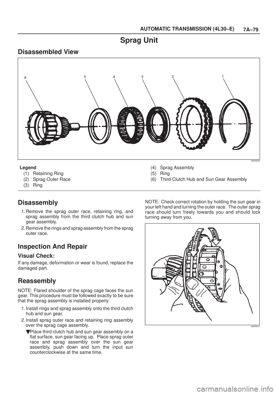
Sprag Unit
Disassembled View
248RS009
Legend
(1) Retaining Ring
(2) Sprag Outer Race
(3) Ring(4) Sprag Assembly
(5) Ring
(6) Third Clutch Hub and Sun Gear Assembly
Disassembly
1. Remove the sprag outer race, retaining ring, and
sprag assembly from the third clutch hub and sun
gear assembly.
2. Remove the rings and sprag assembly from the sprag
outer race.
Inspection And Repair
Visual Check:
If any damage, deformation or wear is found, replace the
damaged part.
Reassembly
NOTE: Flared shoulder of the sprag cage faces the sun
gear. This procedure must be followed exactly to be sure
that the sprag assembly is installed properly.
1. Install rings and sprag assembly onto the third clutch
hub and sun gear.
2. Install sprag outer race and retaining ring assembly
over the sprag cage assembly.
�Place third clutch hub and sun gear assembly on a
flat surface, sun gear facing up. Place sprag outer
race and sprag assembly over the sun gear
assembly, push down and turn the input sun
counterclockwise at the same time. NOTE: Check correct rotation by holding the sun gear in
your left hand and turning the outer race. The outer sprag
race should turn freely towards you and should lock
turning away from you.
248RS010
Page 1664 of 2100
7A±80
AUTOMATIC TRANSMISSION (4L30±E)
Second Clutch
Disassembled View
247RW001
Legend
(1) Retaining Ring
(2) Ring Gear
(3) Retaining Ring
(4) Spacer
(5) Clutch Plates(6) Waved Washer
(7) Retaining Ring
(8) Spring Seat
(9) Springs
(10) Piston Assembly
(11) Second Clutch Drum
Disassembly
1. Remove retaining ring (1) from second clutch drum
(11).
2. Remove ring gear (2), retaining ring (3), and spacer
(4).
3. Remove clutch plates (5) and waved washer (6).
4. Remove retaining ring (7) using J±23327 compressor
to compress the spring seat (8).
5. Remove spring seat (8), springs (9) and piston
assembly (10) from second clutch drum (11).
247RS006
Page 1665 of 2100
7A±81 AUTOMATIC TRANSMISSION (4L30±E)
Inspection And Repair
Visual Check:
If any damage, deformation or wear is found, replace the
damaged part.
Operation Check:
Shake the piston and listen for check ball movement.
Movement indicates proper check ball operation.
Replace the piston if the check ball is missing or falls out.
Reassembly
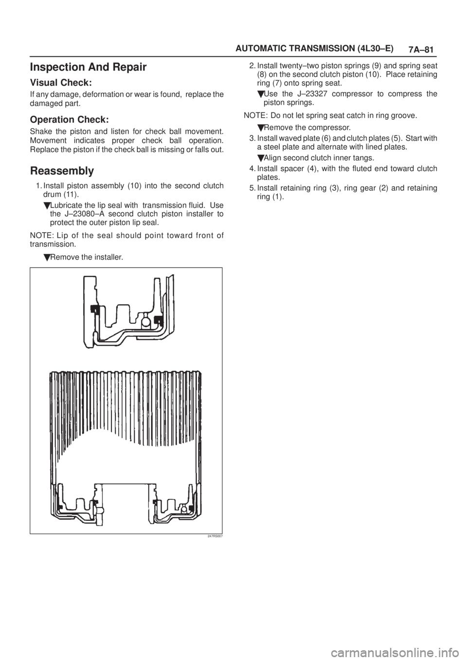
1. Install piston assembly (10) into the second clutch
drum (11).
�Lubricate the lip seal with transmission fluid. Use
the J±23080±A second clutch piston installer to
protect the outer piston lip seal.
NOTE: L ip o f t h e seal should point toward front of
transmission.
�Remove the installer.
247RS007
2. Install twenty±two piston springs (9) and spring seat
(8) on the second clutch piston (10). Place retaining
ring (7) onto spring seat.
�Use the J±23327 compressor to compress the
piston springs.
NOTE: Do not let spring seat catch in ring groove.
�Remove the compressor.
3. Install waved plate (6) and clutch plates (5). Start with
a steel plate and alternate with lined plates.
�Align second clutch inner tangs.
4. Install spacer (4), with the fluted end toward clutch
plates.
5. Install retaining ring (3), ring gear (2) and retaining
ring (1).
Page 1668 of 2100
7A±84
AUTOMATIC TRANSMISSION (4L30±E)
Reverse Clutch Piston And Center Support
Disassembled View
242RY001
Legend
(1) Retaining Ring
(2) Spring Seat
(3) Springs
(4) Piston Assembly
(5) Center Support
(6) Gasket
(7) Transfer Plate
(8) Gasket(9) Restrictor
(10) Retainer Plate
(11) Plug
(12) Spring
(13) Overrun Lock Out Valve
(14) Retainer Plate
(15) Plug
(16) Spring
(17) Reverse Lock Out Control Valve
Disassembly
1. Install the J±23327 compressor tool on spring seat,
then compress the spring seat.
�Remove retaining ring (1).
NOTE: Do not over±stress the springs and seat, as this
will cause damage to the spring seat.
�Remove the compressor tool.
Page 1670 of 2100
7A±86
AUTOMATIC TRANSMISSION (4L30±E)
Overrun Clutch And Turbine Shaft
Disassembled View
252RW005
Legend
(1) Snap Ring
(2) Overdrive Carrier Assembly
(3) Sun Gear
(4) Turbine Shaft
(5) Snap Ring
(6) Backing Plate
(7) Clutch Plates(8) Snap Ring
(9) Overrun Roller Clutch Cam
(10) Roller Clutch Assembly
(11) Overrun Clutch Release Spring Retainer
(12) Diaphragm Spring
(13) Piston Assembly
(14) Overrun Clutch Drum
(15) Turbine Shaft Seal Rings
Page 1671 of 2100
7A±87 AUTOMATIC TRANSMISSION (4L30±E)
Disassembly
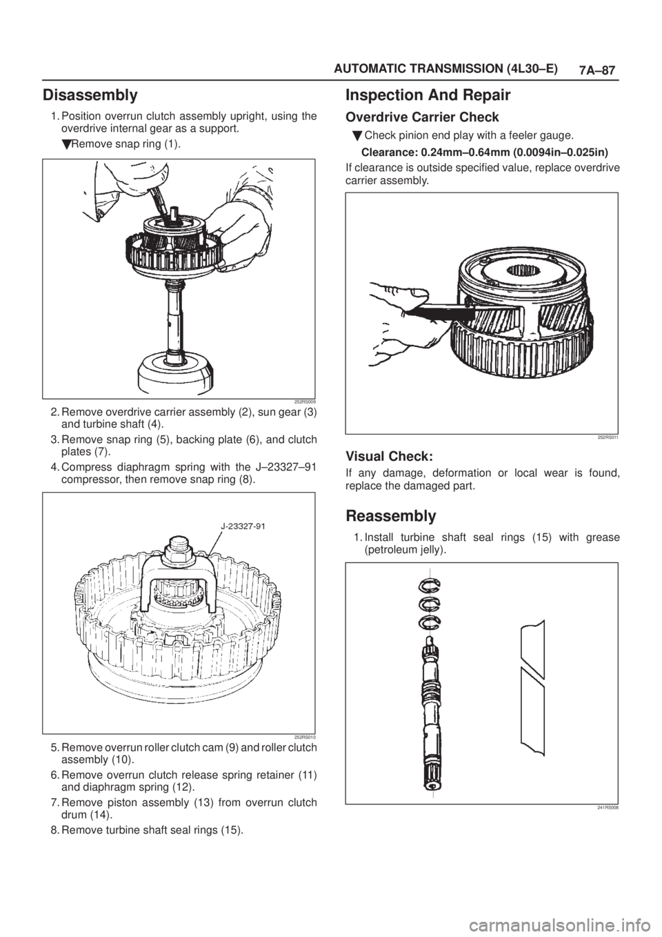
1. Position overrun clutch assembly upright, using the
overdrive internal gear as a support.
�Remove snap ring (1).
252RS009
2. Remove overdrive carrier assembly (2), sun gear (3)
and turbine shaft (4).
3. Remove snap ring (5), backing plate (6), and clutch
plates (7).
4. Compress diaphragm spring with the J±23327±91
compressor, then remove snap ring (8).
252RS010
5. Remove overrun roller clutch cam (9) and roller clutch
assembly (10).
6. Remove overrun clutch release spring retainer (11)
and diaphragm spring (12).
7. Remove piston assembly (13) from overrun clutch
drum (14).
8. Remove turbine shaft seal rings (15).
Inspection And Repair
Overdrive Carrier Check
�Check pinion end play with a feeler gauge.
Clearance: 0.24mm±0.64mm (0.0094in±0.025in)
If clearance is outside specified value, replace overdrive
carrier assembly.
252RS011
Visual Check:
If any damage, deformation or local wear is found,
replace the damaged part.
Reassembly
1. Install turbine shaft seal rings (15) with grease
(petroleum jelly).
241RS008
Page 1672 of 2100
7A±88
AUTOMATIC TRANSMISSION (4L30±E)
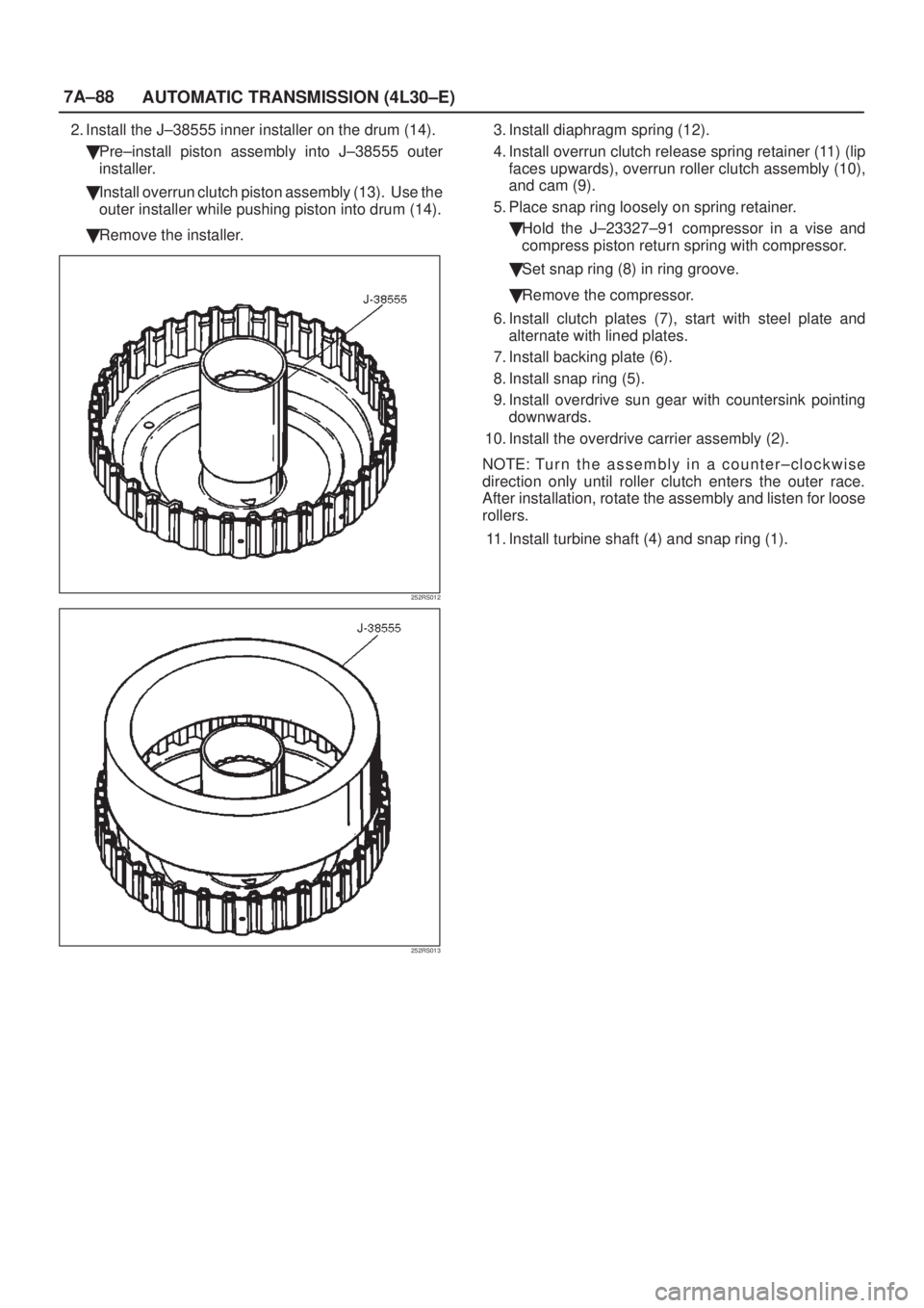
2. Install the J±38555 inner installer on the drum (14).
�Pre±install piston assembly into J±38555 outer
installer.
�Install overrun clutch piston assembly (13). Use the
outer installer while pushing piston into drum (14).
�Remove the installer.
252RS012
252RS013
3. Install diaphragm spring (12).
4. Install overrun clutch release spring retainer (11) (lip
faces upwards), overrun roller clutch assembly (10),
and cam (9).
5. Place snap ring loosely on spring retainer.
�Hold the J±23327±91 compressor in a vise and
compress piston return spring with compressor.
�Set snap ring (8) in ring groove.
�Remove the compressor.
6. Install clutch plates (7), start with steel plate and
alternate with lined plates.
7. Install backing plate (6).
8. Install snap ring (5).
9. Install overdrive sun gear with countersink pointing
downwards.
10. Install the overdrive carrier assembly (2).
NOTE: Tu r n t h e a s sembly in a counter±clockwise
direction only until roller clutch enters the outer race.
After installation, rotate the assembly and listen for loose
rollers.
11. Install turbine shaft (4) and snap ring (1).
Page 1673 of 2100
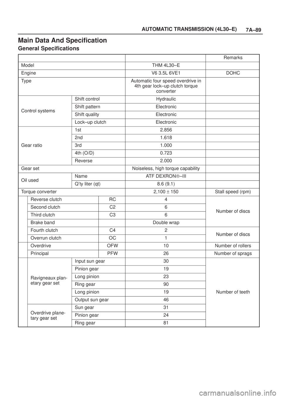
7A±89 AUTOMATIC TRANSMISSION (4L30±E)
Main Data And Specification
General Specifications
Remarks
ModelTHM 4L30±E
EngineV6 3.5L 6VE1DOHC
TypeAutomatic four speed overdrive in
4th gear lock±up clutch torque
converter
Shift controlHydraulic
Control systemsShift patternElectronicControl systemsShift qualityElectronic
Lock±up clutchElectronic
1st2.856
2nd1.618
Gear ratio3rd1.000
4th (O/D)0.723
Reverse2.000
Gear setNoiseless, high torque capability
Oil usedNameATF DEXRON)±IIIOil usedQ'ty liter (qt)8.6 (9.1)
Torque converter2,100 + 150Stall speed (rpm)
Reverse clutchRC4
Second clutchC26Number of discsThird clutchC36Number of discs
Brake bandDouble wrap
Fourth clutchC42Number of discsOverrun clutchOC1Number of discs
OverdriveOFW10Number of rollers
PrincipalPFW26Number of sprags
Input sun gear30
Pinion gear19
Ravigneaux plan-Long pinion23g
etary gear setRing gear90
Long pinion19Number of teeth
Output sun gear46
Odi l
Sun gear31
Overdrive plane-
tary gear setPinion gear24tary gear set
Ring gear81