Page 1650 of 2100
7A±66
AUTOMATIC TRANSMISSION (4L30±E)
242RW004
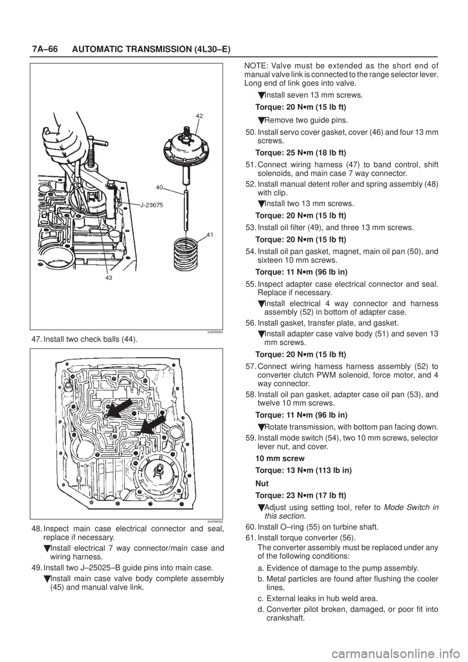
47. Install two check balls (44).
244RW002
48. Inspect main case electrical connector and seal,
replace if necessary.
�Install electrical 7 way connector/main case and
wiring harness.
49. Install two J±25025±B guide pins into main case.
�Install main case valve body complete assembly
(45) and manual valve link.NOTE: Valve must be extended as the short end of
manual valve link is connected to the range selector lever.
Long end of link goes into valve.
�Install seven 13 mm screws.
Torque: 20 Nwm (15 lb ft)
�Remove two guide pins.
50. Install servo cover gasket, cover (46) and four 13 mm
screws.
Torque: 25 Nwm (18 lb ft)
51. Connect wiring harness (47) to band control, shift
solenoids, and main case 7 way connector.
52. Install manual detent roller and spring assembly (48)
with clip.
�Install two 13 mm screws.
Torque: 20 Nwm (15 lb ft)
53. Install oil filter (49), and three 13 mm screws.
Torque: 20 Nwm (15 lb ft)
54. Install oil pan gasket, magnet, main oil pan (50), and
sixteen 10 mm screws.
Torque: 11 Nwm (96 lb in)
55. Inspect adapter case electrical connector and seal.
Replace if necessary.
�Install electrical 4 way connector and harness
assembly (52) in bottom of adapter case.
56. Install gasket, transfer plate, and gasket.
�Install adapter case valve body (51) and seven 13
mm screws.
Torque: 20 Nwm (15 lb ft)
57. Connect wiring harness harness assembly (52) to
converter clutch PWM solenoid, force motor, and 4
way connector.
58. Install oil pan gasket, adapter case oil pan (53), and
twelve 10 mm screws.
Torque: 11 Nwm (96 lb in)
�Rotate transmission, with bottom pan facing down.
59. Install mode switch (54), two 10 mm screws, selector
lever nut, and cover.
10 mm screw
Torque: 13 Nwm (113 lb in)
Nut
Torque: 23 Nwm (17 lb ft)
�Adjust using setting tool, refer to
Mode Switch in
this section.
60. Install O±ring (55) on turbine shaft.
61. Install torque converter (56).
The converter assembly must be replaced under any
of the following conditions:
a. Evidence of damage to the pump assembly.
b. Metal particles are found after flushing the cooler
lines.
c. External leaks in hub weld area.
d. Converter pilot broken, damaged, or poor fit into
crankshaft.
Page 1653 of 2100
7A±69 AUTOMATIC TRANSMISSION (4L30±E)
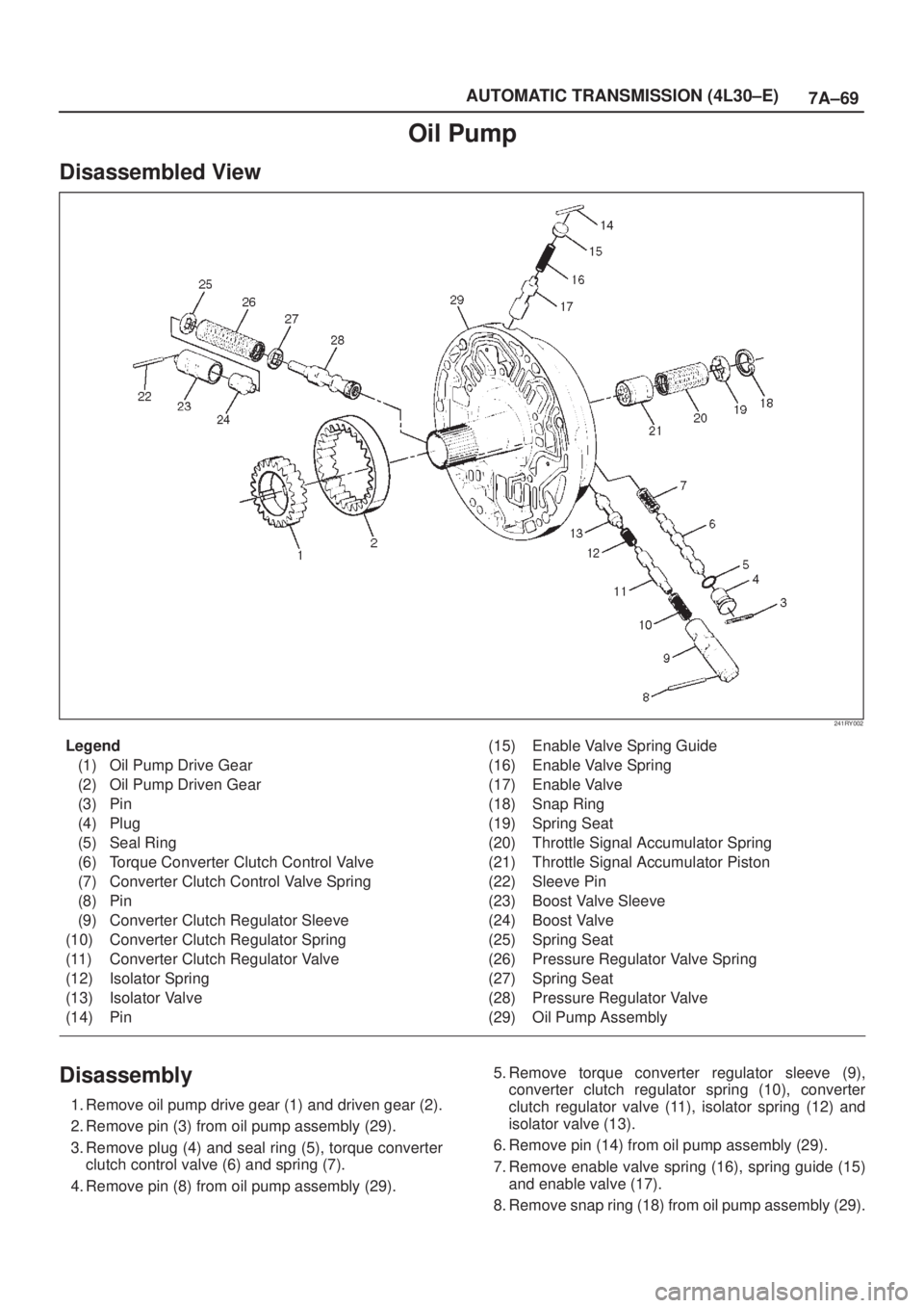
Oil Pump
Disassembled View
241RY002
Legend
(1) Oil Pump Drive Gear
(2) Oil Pump Driven Gear
(3) Pin
(4) Plug
(5) Seal Ring
(6) Torque Converter Clutch Control Valve
(7) Converter Clutch Control Valve Spring
(8) Pin
(9) Converter Clutch Regulator Sleeve
(10) Converter Clutch Regulator Spring
(11) Converter Clutch Regulator Valve
(12) Isolator Spring
(13) Isolator Valve
(14) Pin(15) Enable Valve Spring Guide
(16) Enable Valve Spring
(17) Enable Valve
(18) Snap Ring
(19) Spring Seat
(20) Throttle Signal Accumulator Spring
(21) Throttle Signal Accumulator Piston
(22) Sleeve Pin
(23) Boost Valve Sleeve
(24) Boost Valve
(25) Spring Seat
(26) Pressure Regulator Valve Spring
(27) Spring Seat
(28) Pressure Regulator Valve
(29) Oil Pump Assembly
Disassembly
1. Remove oil pump drive gear (1) and driven gear (2).
2. Remove pin (3) from oil pump assembly (29).
3. Remove plug (4) and seal ring (5), torque converter
clutch control valve (6) and spring (7).
4. Remove pin (8) from oil pump assembly (29).5. Remove torque converter regulator sleeve (9),
converter clutch regulator spring (10), converter
clutch regulator valve (11), isolator spring (12) and
isolator valve (13).
6. Remove pin (14) from oil pump assembly (29).
7. Remove enable valve spring (16), spring guide (15)
and enable valve (17).
8. Remove snap ring (18) from oil pump assembly (29).
Page 1654 of 2100
7A±70
AUTOMATIC TRANSMISSION (4L30±E)
9. Remove spring seat (19), spring (20) and throttle
signal accumulator piston (21).
10. Remove sleeve pin (22) from oil pump assembly (29).
11. Remove boost valve sleeve (23), boost valve (24),
spring seat (25), valve spring (26), spring seat (27),
and pressure regulator valve (28).
Inspection And Repair
Visual Check:
If any damage, deformation or wear is found, replace the
damaged part.
Reassembly
1. Lubricate and preinstall pressure regulator spring
seat (27) on valve (28), with the flat side against
shoulder.
2. Install pressure regulator valve (28) and spring seat
(27) assembly, valve spring (26), and spring seat (25)
with the flat side away from spring to oil pump
assembly (29).
3. Assemble boost valve (24) into sleeve (23).
4. Install boost valve and sleeve assembly, and sleeve
pin (22) to oil pump assembly (29).
5. Install throttle signal accumulator piston (21), spring
(20), and spring seat (19), with the flat side away from
the spring, and snap ring (18) to oil pump assembly
(29).
6. Install enable valve (17), spring guide (15), enable
valve spring (16) and retainer pin (14) to oil pump
assembly (29).
7. Assemble torque converter regulator spring (10) and
torque converter regulator valve (11) into sleeve (9).
8. Install isolator valve (13), isolator valve spring (12)
and the torque converter regulator sleeve and valve
assembly into the oil pump assembly (29).
9. Install torque converter clutch control valve spring (7),
torque converter clutch control valve (6), plug (4) and
seal ring (5), and retainer pin (3) to oil pump assembly
(29).
10. Install oil pump driven gear (2) and drive gear (1).
Page 1657 of 2100
7A±73 AUTOMATIC TRANSMISSION (4L30±E)
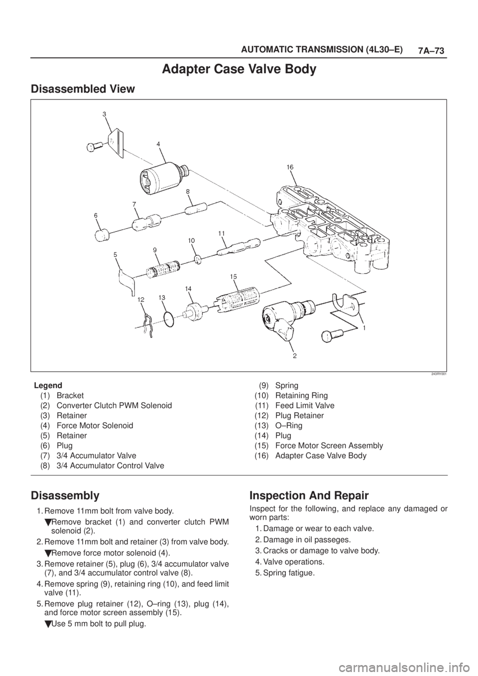
Adapter Case Valve Body
Disassembled View
243RY001
Legend
(1) Bracket
(2) Converter Clutch PWM Solenoid
(3) Retainer
(4) Force Motor Solenoid
(5) Retainer
(6) Plug
(7) 3/4 Accumulator Valve
(8) 3/4 Accumulator Control Valve(9) Spring
(10) Retaining Ring
(11) Feed Limit Valve
(12) Plug Retainer
(13) O±Ring
(14) Plug
(15) Force Motor Screen Assembly
(16) Adapter Case Valve Body
Disassembly
1. Remove 11mm bolt from valve body.
�Remove bracket (1) and converter clutch PWM
solenoid (2).
2. Remove 11mm bolt and retainer (3) from valve body.
�Remove force motor solenoid (4).
3. Remove retainer (5), plug (6), 3/4 accumulator valve
(7), and 3/4 accumulator control valve (8).
4. Remove spring (9), retaining ring (10), and feed limit
valve (11).
5. Remove plug retainer (12), O±ring (13), plug (14),
and force motor screen assembly (15).
�Use 5 mm bolt to pull plug.
Inspection And Repair
Inspect for the following, and replace any damaged or
worn parts:
1. Damage or wear to each valve.
2. Damage in oil passeges.
3. Cracks or damage to valve body.
4. Valve operations.
5. Spring fatigue.
Page 1658 of 2100
7A±74
AUTOMATIC TRANSMISSION (4L30±E)
Reassembly
1. Install force motor screen assembly (15), plug (14),
O±ring (13), and plug retainer (12).
2. Install feed limit valve (11), retaining ring (10), and
spring (9).
3. Install 3/4 accumulator control valve (8), 3/4
accumulator valve (7), plug (6), and retainer (5).
4. Install force motor solenoid (4).
�Place solenoid terminals pointing towards mating
face.
�Install retainer (3) and bolt.
Torque: 10 Nwm (87 lb in)
5. Install converter clutch PWM solenoid (2) with two
O±rings (2) and bracket (1) to valve body.
�Install bolt.
Torque: 10 Nwm (87 lb in)
Page 1659 of 2100
7A±75 AUTOMATIC TRANSMISSION (4L30±E)
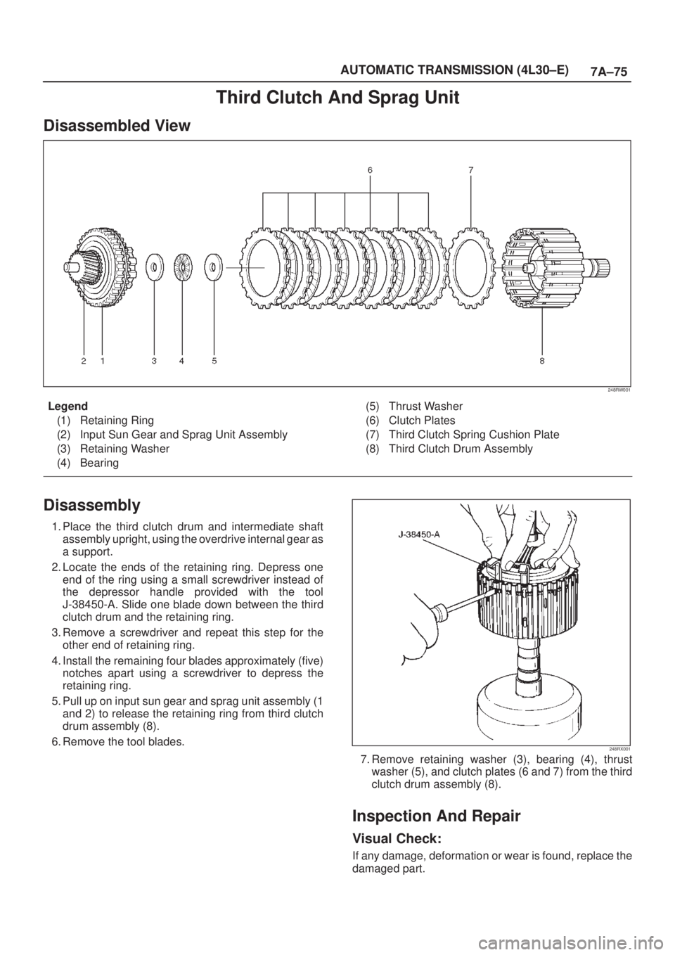
Third Clutch And Sprag Unit
Disassembled View
248RW001
Legend
(1) Retaining Ring
(2) Input Sun Gear and Sprag Unit Assembly
(3) Retaining Washer
(4) Bearing(5) Thrust Washer
(6) Clutch Plates
(7) Third Clutch Spring Cushion Plate
(8) Third Clutch Drum Assembly
Disassembly
1. Place the third clutch drum and intermediate shaft
assembly upright, using the overdrive internal gear as
a support.
2. Locate the ends of the retaining ring. Depress one
end of the ring using a small screwdriver instead of
the depressor handle provided with the tool
J-38450-A. Slide one blade down between the third
clutch drum and the retaining ring.
3. Remove a screwdriver and repeat this step for the
other end of retaining ring.
4. Install the remaining four blades approximately (five)
notches apart using a screwdriver to depress the
retaining ring.
5. Pull up on input sun gear and sprag unit assembly (1
and 2) to release the retaining ring from third clutch
drum assembly (8).
6. Remove the tool blades.
248RX001
7. Remove retaining washer (3), bearing (4), thrust
washer (5), and clutch plates (6 and 7) from the third
clutch drum assembly (8).
Inspection And Repair
Visual Check:
If any damage, deformation or wear is found, replace the
damaged part.
Page 1660 of 2100
7A±76
AUTOMATIC TRANSMISSION (4L30±E)
Reassembly
1. Place third clutch drum and intermediate shaft
assembly upright, using the overdrive internal gear as
a support.
2. Install third clutch spring cushion plate (7), bevel face
down.
3. Install third clutch plates (6) into third clutch drum
assembly (8). Start with the steel clutch plate and
alternate with lined plates.
4. Install thrust washer (5), bearing (4), and retaining
washer (3).
5. Fully engage the hub splines of the input sun gear and
sprag unit assembly (2) into the third clutch inner
tangs.
�Simultaneously rotate the outer sprag race to
engage into the third clutch drum assembly (8).
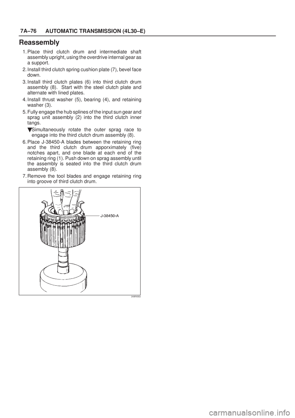
6. Place J-38450-A blades between the retaining ring
and the third clutch drum apporximately (five)
notches apart, and one blade at each end of the
retaining ring (1). Push down on sprag assembly until
the assembly is seated into the third clutch drum
assembly (8).
7. Remove the tool blades and engage retaining ring
into groove of third clutch drum.
248RX002
Page 1661 of 2100
7A±77 AUTOMATIC TRANSMISSION (4L30±E)
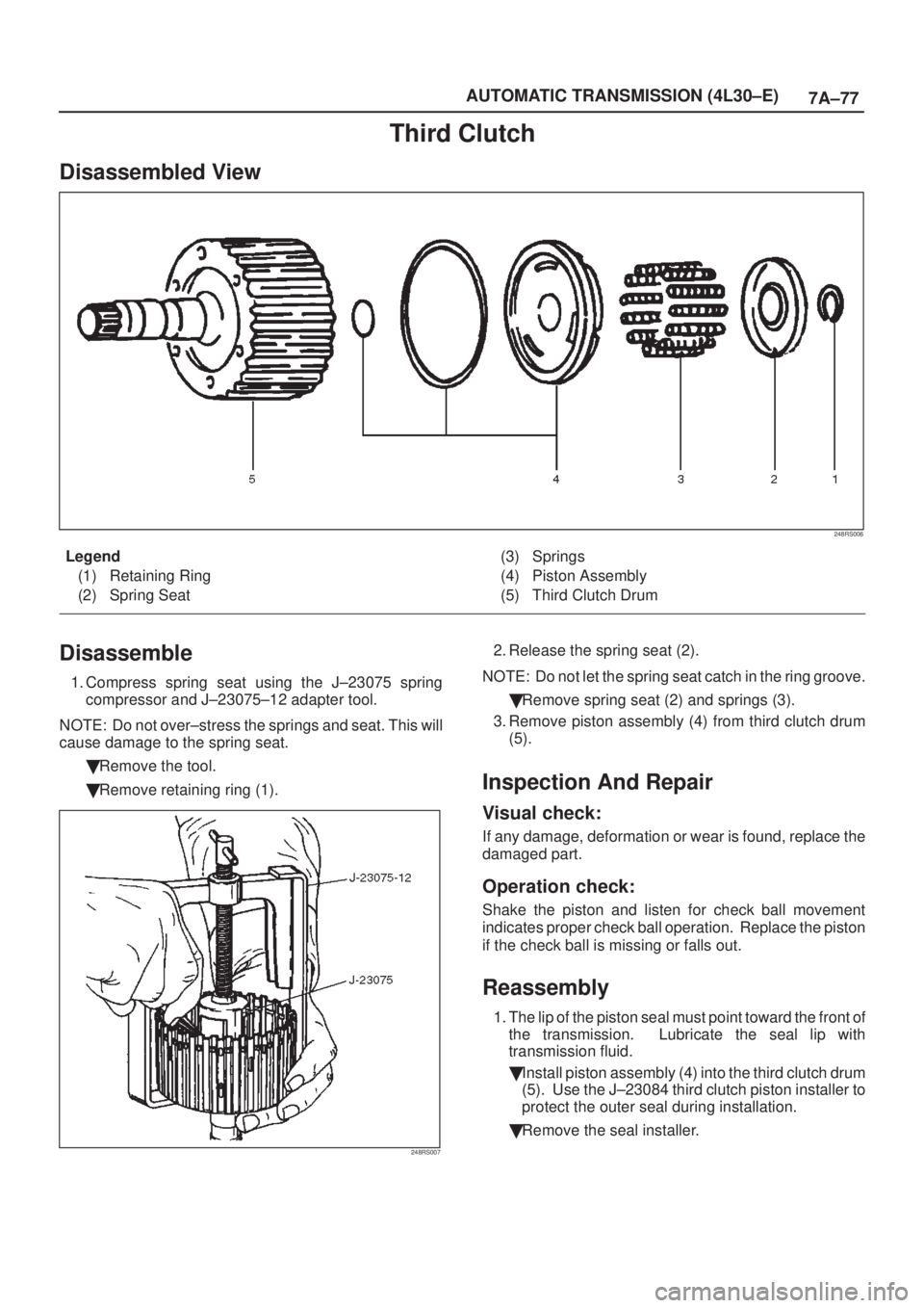
Third Clutch
Disassembled View
248RS006
Legend
(1) Retaining Ring
(2) Spring Seat(3) Springs
(4) Piston Assembly
(5) Third Clutch Drum
Disassemble
1. Compress spring seat using the J±23075 spring
compressor and J±23075±12 adapter tool.
NOTE: Do not over±stress the springs and seat. This will
cause damage to the spring seat.
�Remove the tool.
�Remove retaining ring (1).
248RS007
2. Release the spring seat (2).
NOTE: Do not let the spring seat catch in the ring groove.
�Remove spring seat (2) and springs (3).
3. Remove piston assembly (4) from third clutch drum
(5).
Inspection And Repair
Visual check:
If any damage, deformation or wear is found, replace the
damaged part.
Operation check:
Shake the piston and listen for check ball movement
indicates proper check ball operation. Replace the piston
if the check ball is missing or falls out.
Reassembly
1. The lip of the piston seal must point toward the front of
the transmission. Lubricate the seal lip with
transmission fluid.
�Install piston assembly (4) into the third clutch drum
(5). Use the J±23084 third clutch piston installer to
protect the outer seal during installation.
�Remove the seal installer.