Page 542 of 2100

4C±45 DRIVE SHAFT SYSTEM
General Description
This publication contains essential removal, installation,
adjustment and maintenance procedures.
The front axle utilizes a central disconnect type front
axle/transfer case system.The drive axles are completely flexible assemblies,
consisting of inner and outer constant velocity (CV) drive
shaft joints connected by an axle shaft.
For description of front propeller shaft and universal joint,
refer to
Front Propeller Shaft in this section.
Diagnosis
ConditionPossible causeCorrection
Oil Leak At Front AxleWorn or defective oil seal.Replace the oil seal.
Front axle housing cracked.Repair or replace.
Oil Leak At Pinion ShaftToo much gear oil.Correct the oil level.
Oil seal worn or defective.Replace the oil seal.
Pinion flange loose or damaged.Tighten or replace.
Noises In Front Axle Drive Shaft
JointBroken or worn drive shaft joints and
bellows (BJ and DOJ).Replace the drive shaft joints and
bellows.
ªClankº When Accelerating From
ªCoastºLoose drive shaft joint to output shaft
bolts.Tighten.
Damaged inner drive shaft joint.Replace.
Shudder or Vibration During
Acceleration
Excessive drive shaft joint angle.Repair.
AccelerationWorn or damaged drive shaft joints.Replace.
Sticking spider assembly (inner drive
shaft joint).Lubricate or replace.
Sticking joint assembly (outer drive
shaft joint).Lubricate or replace.
Vibration At Highway SpeedsOut of balance or out of round tires.Balance or replace.
Front end out of alignment.Align.
Noises in Front AxleInsufficient gear oil.Replenish the gear oil.
Wrong or poor grade gear oil.Replace the gear oil.
Drive pinion to ring gear backlash
incorrect.Adjust the backlash.
Worn or chipped ring gear, pinion
gear or side gear.Replace the ring gear, pinion gear or
side gear.
Pinion shaft bearing worn.Replace the pinion shaft bearing.
Hub unit bearing worn.Replace the hub unit bearing.
Differential bearing loose or worn.Tighten or replace.
Wanders and PullsIncorrect front alignment.Adjust the front alignment.
Steering unit loose or worn.Tighten or replace.
Tire worn or improperly inflated.Adjust the inflation or replace.
Front or rear suspension parts loose
or broken.Tighten or replace.
Front Wheel ShimmyHub unit bearing worn.Replace.
Incorrect front alignment.Adjust the front alignment.
Worn ball joint or bush.Replace the ball joint or bush.
Steering unit loose or worn.Tighten or replace.
Tire worn or improperly inflated.Replace or adjust the inflation.
Shock absorber worn.Replace the shock absorber.
Page 543 of 2100
4C±46
DRIVE SHAFT SYSTEM
Front Hub and Disc (2WD Model)
Disassembled View
411R200011
Legend
(1) Disc Rotor
(2) Hub unit, Bearing(3) Wheel Pin
(4) Bolt
Disassembly
1. Raise the vehicle with a jack. Support the frame with
chassis stands.
2. Remove the brake caliper from the bracket. Secure
the caliper with a wire so that it does not interfere with
the work process.
Refer to
Front disc caliper assembly in Section 5C of this
Manual.
3. Remove the disk rotor
Apply penetrating oil to the bearing and disc rotor contact
surfaces if the surfaces are stuck together because of
rust.
4. Inspect the hub unit bearing. Refer to
Inspection
below.
5. Use a dial gauge to measure the bearing axial rattle.
Bearing axial rattle: 0.05 mm max
411R200002
Page 544 of 2100

4C±47 DRIVE SHAFT SYSTEM
If abnormal conditions are discovered during
inspection, go to Step 6. If there are no abnormal
conditions, reassemble the front disc rotor and
caliper.
NOTE: Hub, wheel bearing and spindle is integrated to
the hub unit bearing so it must not be disassembled. If it
has abnormal rattle or noise, replace the hub unit bearing.
6. Remove the ABS sensor connector.
411R200004
Legend
(1) ABS Sensor Connector
(2) Bolt
7. Remove the 4 bolts fixing the hub unit bearing to the
knuckle.
Apply penetrating oil to the bearing and knuckle contact
surfaces if the surfaces are stuck together because of
rust.
8. Temporarily install long bolts to 2 of the fixing bolt
holes (the bolts must have the same diameter and
thread width).
9. Strike the long bolts with a hammer to loosen and
remove the hub unit bearing from the knuckle.
Take care not to drop the bearing.10. If necessary, replace the wheel pin in the following
manner.
�Place hub on a suitable work surface and remove
wheel studs, as required, using a hammer.
411RS004
Inspection
Inspect the parts listed below for abrasion, breakage, and
other abnormal conditions.
Repair, or replace the parts as required.
�Disc
�Caliper
�Wheel pin
�Hub unit bearing
Page 545 of 2100
4C±48
DRIVE SHAFT SYSTEM
Reassembly
1. Install wheel pin.
411RS005
�Place hub on a wood workbench or a block of wood
approx. 6º by 6º to protect the wheel stud ends and
threads.
�Install wheel stud, using a hammer.
NOTE: Be sure wheel stud is started squarely and seats
completely.
2. Install the hub unit bearing to the knuckle.
Tighten the bolts to the specified torque.
Hub unit bearing bolt
Torque: 103+10 N´m (10.5 + 1 kg´m)
If there is rust on the bearing and knuckle contact
surfaces, use sandpaper to remove it before installation.
3. Install the ABS sensor connector.
4. Install the disc rotor.
5. Install the brake caliper to the bracket.
Refer to
Front disc caliper assembly in Section 5C of this
Manual.
Page 546 of 2100
4C±49 DRIVE SHAFT SYSTEM
Front Hub and Disc (4WD Model)
Disassembled View
411R200010
Legend
(1) Disc Rotor
(2) Hub Unit, Bearing(3) Wheel Pin
(4) ABS Sensor Ring
(5) Bolt
Disassembly
1. Move the transfer case lever to the 2WD position.
2. Raise the vehicle with a jack. Support the frame with
chassis stands.
3. Remove the brake caliper from the bracket. Secure
the caliper with a wire that it does not interfare with the
work process.Refer to
Front disc caliper assembly in Section 5C of this
Manual.
4. Remove the disk rotor.
Apply penetrating oil to the bearing and disc rotor contact
surfaces if the surfaces are stuck together because of
rust.
5. Inspect the hub unit bearing. Refer to
inspection
below.
Page 547 of 2100

4C±50
DRIVE SHAFT SYSTEM
6. Use a dial gauge to measure the bearing axial rattle.
Bearing axial rattle: 0.05 mm max
411R200002If abnormal conditins are discovered during
inspection, go to Step 7. If there are no abnormal
conditions, reassemble the front discrotor and
caliper.
NOTE: Hub, wheel bearing and spindle is integrated to
the hub unit bearing so it must not be disassembled. If it
has abnormal rattle or noize, replace the hub unit bearing.
7. Loosen the caulking around the front drive shaft nuts.
8. Remove the nuts and discard them (they cannot be
reused).
9. Remove the 4 bolts fixing the hub unit bearing to the
knuckle.
Apply penetrating oil to the bearing and knuckle contact
surfaces if the surfaces are stuck together because of
rust.
10. Temporarily install long bolts to 2 of the fixing bolt
holes (the bolts must have the same diameter and
thread width).
411R200012
Legend
(1) Bolt
11. Strike the long bolts with a hammer to loosen and
remove the hub unit bearing from the knuckle.
�Take care not to strike the front drive shaft.
�Take care not to drop the bearing.
12. Remove the ABS rotor sensor from the bearing.
13. If necessary, replace the wheel pin in the following
manner.
�Place hub on a suitable work surface and remove
wheel studs, as required, using a hammer.
411RS004
Inspection
Inspect the parts listed below for abrasion, breakage, and
other abnormal conditions.
Repair or replace the parts as required.
�Disc
�Caliper
�Drive shaft oil seal
�ABS sensor rotor
�Wheel pin
�Hub unit bearing
Page 548 of 2100

4C±51 DRIVE SHAFT SYSTEM
Reassembly
1. Install the wheel pin.
�Place hub on a wood workbench or a block of wood
approx. 6º by 6º to protect the wheel stud ends and
threads.
�Install the wheel stud, using a hammer.
NOTE: Be sure wheel stud is started squarely and seats
completely.
411RS005
2. Install the ABS rotor sensor to the hub unit bearing.
Tighten the bolts to the specified torque.
ABS rotor sensor bolt
Torque: 18.7+5 N´m (1.9+0.5 kg´m)
3. Install the hub unit bearing to the knuckle. Tighten the
bolts to the specified torque.
Hub unit bearing bolt
Torque: 103+10 N´m (10.5+1 kg´m)
If there is rust on the bearing and knuckle contact
surfaces, use sandpaper to remove it before installation.
Take care not to push the front drive shaft and oil seal out
of position.
4. Hand tighten the front drive shaft nuts.
Use new nuts.
5. Install the disc rotor.
6. Install the brake caliper to the bracket.
Refer to
Front disc caliper assembly in Section 5C of this
Manual.7. Tighten the front drive shaft nuts to the specified
torque.
Front drive shaft nut
Torque: 245+19.6 N´m (25+2 kg´m)
411R200005
8. Caulk the front drive shaft nuts.
The caulking must be free of cracks.
411R200006
Page 549 of 2100
4C±52
DRIVE SHAFT SYSTEM
Front Drive Shaft Joint
Front Drive Shaft Joints
Replacement
�Refer to Front Drive Axle Assembly Replacement in
this section, and refer to
Front Hub and Disc Overhaul
in Suspension section.
Front Hub Bearing Preload Check
Check the hub bearing preload at the wheel pin.
New bearing and New oil seal:
24.5 N (4.4 ± 5.5 lb)
Used bearing and New oil seal:
11.8± 17.7 N(2.6 ± 4.0 lb)
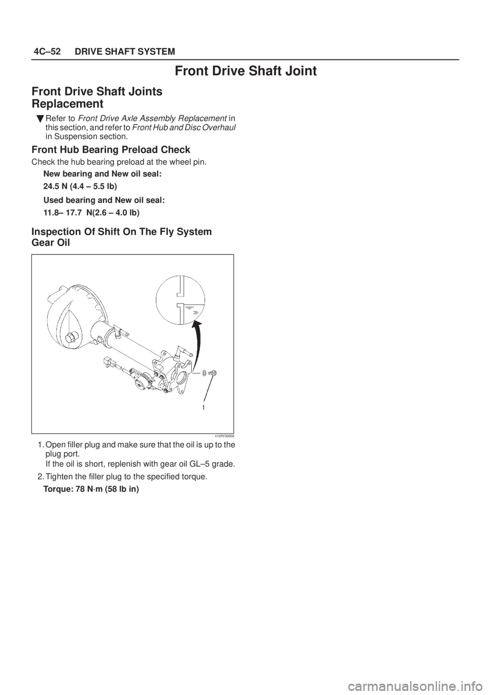
Inspection Of Shift On The Fly System
Gear Oil
412RY00008
1. Open filler plug and make sure that the oil is up to the
plug port.
If the oil is short, replenish with gear oil GL±5 grade.
2. Tighten the filler plug to the specified torque.
Torque: 78 N´m (58 lb in)

Disassembled View
411R200011
Legend
(1) Disc Rotor
(2) Hub unit, Bearing(3) Wheel Pin
(4) Bolt
Disassembly
1. Raise the vehicle with a jack. Su")


Disassembled View
411R200010
Legend
(1) Disc Rotor
(2) Hub Unit, Bearing(3) Wheel Pin
(4) ABS Sensor Ring
(5) Bolt
Disassembly
1. Move the tran")