7A1±22
TRANSMISSION CONTROL SYSTEM (4L30±E)
IMPORTANT:Only four Fail Records can be stored.
Each Fail Record is for a different DTC. It is possible that
there will not be Fail Records for every DTC if multiple
DTCs are set.
Clear DTC
NOTE: If you clear the DTC (Diagnostic Trouble Codes)
you will not be able to read any codes recorded during the
last occurrence.
NOTE: To use the DTC again to identify a problem, you
will need to reproduce the fault or the problem. This may
require a new test drive or just turning the ignition on (this
depends on the nature of the fault).
1. If you have a Tech 2:
1. Connect the Tech 2 if it is still not connected GO
THROUGH Tech 2 OBD II CONNECTION.
2. Push ªF1: Clear DTC Informationº in the
Application Menu and answer ªYesº to the
question ªDo you want to clear DTC's?º
a. When a malfunction still exists and the Tech 2
displays ª4L30E CODES NOT CLEAREDº. This
means that the problem is still there or that the
recovery was not done. Please GO TO DTC
CHECK.
b. When a malfunction has been repaired and the
recovery is done. The Tech 2 displays ª4L30E
CODES CLEAREDº.
2. If you have no Tech 2:
Disconnect the PCM battery feed as necessary.
DTC Check
1. Diagnostic Trouble Codes (DTC) have been identified
by Tech 2.
2. You have written the list of the DTCs. The order of the
malfunctions has no meanings for this PCM. Usually
only one or two malfunctions should be set for a given
problem.
3. Check directly the DTCs you identified. The DTCs are
sorted by number. Refer to
Diagnostic Trouble Code
(DTC) Identification in this section.
PCM Precaution
The PCM can be damaged by:
1. Electrostatic discharge
2. The short circuit of some terminals to voltage or to
ground.
Electrostatic Discharge Damage Description:
1. Electronic components used to control systems are
often designed to carry very low voltage, and are very
susceptible to damage caused by electrostatic
discharge. It is possible for less than 100 volts of
static electricity to cause damage to some electronic
components. By comparison, it takes as much as
4,000 volts for a person to even feel the zap of a static
discharge.2. There are several ways for a person to become
statically charged. The most common methods of
charging are by friction and induction. An example of
charging by friction is a person sliding across a car
seat, in which a charge of as much as 25,000 volts
can build up. Charging by induction occurs when a
person with well insulated shoes stands near a highly
charged object and momentarily touches ground.
Charges for the same polarity are drained off, leaving
the person highly charged with the opposite polarity.
Static charges of either type can cause damage,
therefore, it is important to use care when handling
and testing electronic components.
NOTICE: To prevent possible electrostatic
discharge damage:
1. Do not touch the PCM connector pins or soldered
components on the PCM circuit board.
2. Be sure to follow the guidelines listed below if
servicing any of these electronic components:
3. Do not open the replacement part package until it is
time to install the part.
4. Avoid touching electrical terminals of the part.
5. Before removing the part from its package, ground
the package to a known good ground on the vehicle.
6. Always touch a known good ground before handling
the part. This step should be repeated before
installing the part if the part has been handled while
sliding across the seat, while sitting down from a
standing position or while walking some distance.
Information On PCM
1. The Powertrain Control Module (PCM) is located in
the center console and is the control center of the
electronic transmission control system.
2. The PCM must be maintained at a temperature below
85� (185�F) at all times. This is most essential if the
vehicle is put through a paint baking process. The
PCM will become inoperative if its temperature
exceeds 85�C (185�F). Therefore, it is
recommended that the PCM be removed or that
temporary insulation be placed around the PCM
during the time the vehicle is in a paint oven or other
high temperature process.
3. The PCM is designed to process the various inputs
and then respond by sending the appropriate
electrical signals to control transmission upshift,
downshift, shift feel and torque converter clutch
engagement.
4. The PCM constantly interprets information from the
various sensors, and controls the systems that affect
transmission and vehicle performance. By analyzing
operational problems, the PCM is able to perform a
diagnostic function by displaying DTC(s) and aid the
technician in making repairs.
7A1±54
TRANSMISSION CONTROL SYSTEM (4L30±E)
�The PCM will illuminate the CHECK TRANS Lamp.
�Turn force motor OFF.
Conditions For Clearing The DTC/CHECK
TRANS Lamp
�The PCM will turn ªoffº the CHECK TRANS Lamp
after three consecutive ignition cycles without a
failure reported.
�The DTC can be cleared from PCM memory by using
a scan tool.
�The DTC can also be cleared from memory when the
vehicle has made 40 warmup cycles without a failure
reported.
�The PCM will cancel the DTC Actions Taken items
when the fault conditions no longer exist and the
ignition is cycles ªoffº long enough to power down the
PCM.
Diagnostic Aids
�Check for intermittent output speed sensor circuit
problems.
�Check for possible incorrect calibration. (PCM part
No., tire specification, and rear axle ratio)
Test Description
The numbers below refer to the step numbers on the
diagnostic chart:
3. This step checks for possible low fluid level causing
slipping resulting in an undefined gear ratio.
4. This step checks for correct gear ratios for
commanded gears.
5. This step checks for low line pressure.
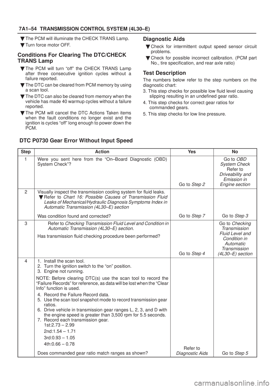
DTC P0730 Gear Error Without Input Speed
StepActionYe sNo
1Were you sent here from the ªOn±Board Diagnostic (OBD)
System Checkº?
Go to Step 2
Go to OBD
System Check
Refer to
Driveability and
Emission in
Engine section
2Visually inspect the transmission cooling system for fluid leaks.
�Refer to
Chart 16: Possible Causes of Transmission Fluid
Leaks of Mechanical/Hydraulic Diagnosis Symptoms Index in
Automatic Transmission (4L30±E) section
Was condition found and corrected?Go to Step 7Go to Step 3
3Refer to Checking Transmission Fluid Level and Condition in
Automatic Transmission (4L30±E) section.
Has transmission fluid checking procedure been performed?
Go to Step 4
Go to Checking
Transmission
Fluid Level and
Condition in
Automatic
Transmission
(4L30±E) section
41. Install the scan tool.
2. Turn the ignition switch to the ªonº position.
3. Engine not running.
NOTE: Before clearing DTC(s) use the scan tool to record the
ªFailure Recordsº for reference, as data will be lost when the ªClear
Infoº function is used.
4. Record the Failure Record data.
5. Use the scan tool snapshot mode to record transmission gear
ratios.
6. Drive vehicle in transmission gear ranges L, 2, 3, and D with
the engine speed is greater than 3,500 rpm for 5.5 seconds.
7. Record each transmission gear.
1st:2.73 ± 2.99
2nd:1.54 ± 1.71
3rd:0.93 ± 1.05
4th:0.66 ± 0.78
Does commanded gear ratio match ranges as shown?
Refer to
Diagnostic AidsGo to Step 5

IMPORTANT:Only four Fail Records can be stored.
Each Fail Record is for a different DTC. It is possible that
there will not be Fail Records for every DTC")