2002 ISUZU AXIOM power steering
[x] Cancel search: power steeringPage 320 of 2100

4A1±7 DIFFERENTIAL (FRONT)
3. Tighten the mounting bolts and nuts to the specified
torque.
Torque: 168 N´m (124 lb ft)
412R200004
4. Install the right side knuckle with lower control arm to
the upper control arm.
Refer to
Knuckle in Suspension section.
CAUTION: Carefully insert the drive shaft into the
knuckle, to avoid damaging the oil seal.
5. Align the bolt hole of the lower control arm, then install
the bolts and nuts.
NOTE: Adjust the buffer clearance before tightening the
bolts and nuts of the lower control arm.
6. Install the hose of the shift on the fly.
7. Install the actuator connector of the shift on the fly.
8. Install the tie-rod end of the power steering unit to the
knuckle, tighten the nut to the specified torque.
Torque: 118 N´m (87 lb ft)
9. Install lower bolts and nuts of the shock absorber,
tighten it to the specified torque.
Torque: 93 N´m (69 lb ft)
10. Install lower nuts of the stabilizer link, tighten it to the
specified torque.
11. Install the suspension crossmember.
12. Install the torsion bar.
Refer to
Torsion Bar in Suspension section.
13. Install the front propeller shaft.
Refer to
Front Propeller Shaft in this section.
14. Install the hub and disc assembly and adjust the
bearing preload.
Refer to
Front Hub and Disc in this section.
15. Install the wheel speed sensor of the antilock brake
system.
16. Install the brake caliper. Tighten the bolt of the caliper
bracket to the specified torque.
Torque: 50 N´m (37 lb ft)
17. Install the stone guard.18. Install the tire and wheel.
19. Lower the vehicle, adjust the trim height.
Refer to
Trim Height Adjustment in Steering section.
20. Tighten the bolts and nuts of the lower control arm to
the specified torque.
Refer to
Lower Control Arm in Suspension section.
Page 395 of 2100

DRIVE LINE CONTROL SYSTEM (TOD) 4B2±16
How to Clear The Trouble Code
The trouble codes saved to the control unit can be deleted
by the following procedure if the starter switch is being in
the OFF position.
1. Short-circuit terminal 8 of the self-diagnostic
connector to GND (terminal 4 or 5).
2. Turn on the starter switch while maintaining the state
of step1, and stop short-circuiting terminal 8 to GND
within five seconds.
826R200011
3. If the conditions shown in steps 1 and 2 are met, the
trouble codes saved to the control unit are cleared.
(After the codes are completely deleted, the code 12
that indicates the normal condition is continuously
displayed.)
Precautions on Diagnosis
Replacement of Control Unit
The control unit itself rarely fails. In most cases, the
harnesses have failed (i.e. short-circuit) to cause
secondary troubles. Other cases include that the cause
has been unknown due to intermittent occurrence of
troubles and the troubles are removed accidentally along
with replacement of control unit, resulting in misjudgment
of cause. Therefore, before replacing the control unit,
check the connector joints and whether the unspecified
current flows in the control unit due to short-circuit
between harnesses.
Trouble Intermittently Observed
Troubles intermittently observed are mostly attributable
to temporary imperfect connection of harnesses and
connectors.
When such troubles are found, check the associated
circuit according to the following procedure.
1. Check whether improper connectors are plugged in
or connector terminals are completely engaged.
2. Check whether the terminals are deformed or
damaged. If yes, remove the deformation or damage
and connect the terminals securely.3. It is likely that wires in the harness are falsely broken.
Therefore, in examination of failed harness circuit,
shake the harness for check to such extent that the
harness will not be damaged.
Test Run of Failed TOD Vehicle
If the TOD indicator lamps experienced faulty operation
even once in the past, the failed portion can be identified
by use of the procedure ªDiagnosis from Trouble Codesº
or ªTrouble Diagnosis Depending on the Status of TOD
Indicatorº. If the troubles that are only recognized as
abnormal phenomena of the vehicle by the driver are
observed, conduct the test run in the following procedure
to reproduce the faulty phenomena and diagnose the fault
for each phenomenon.
1. Start the engine, and check that the TOD indicator
lamps are turned on for about two seconds for initial
check; the CHECK lamp goes off; and the TOD
indicator lamps display the specified drive mode. (If
the CHECK lamp starts blinking, read the trouble
codes and identify the failed portion.)
2. While keeping the vehicle standstill, operate the TOD
switch to change the modes: 2H mode"TOD
mode"4L mode"TOD mode"2H mode. Check
that the TOD indicator lamps correctly display the
status whenever the mode is changed. If the
transition status is displayed during the shift
operation, run the vehicle a little to complete shifting.
3. Slowly start the vehicle in the TOD mode, and add the
power to accelerate to at least 40 km/h (25 mph)and
maintain the speed for about two minutes. Apply the
brake to completely stop the vehicle. Repeat this test
pattern at least three times.
4. Turn the steering to the right end (or left end) in the
TOD mode, and slowly start the vehicle and make a
circle five times. Next, conduct the same test in the 2H
mode.
5. Slowly start the vehicle in the TOD mode, and
accelerate to at least 40 km/h (25 mph). Keep the
established speed, carefully change the mode in the
sequence ªTOD mode"2H mode "TOD modeº
while checking that the shift is complete in each mode
change. After the test, apply the brake to completely
stop the vehicle.
6. Slowly start the vehicle in the TOD mode, and
accelerate to at least 40 km/h (25 mph). Apply the
brake strongly so that the ABS works, and completely
stop the vehicle.
7. Slowly start the vehicle in the 4L mode, and
accelerate to at least 20 km/h (13 mph). Apply the
brake to completely stop the vehicle.
If the CHECK lamp starts blinking during the test run, read
the trouble codes and give appropriate maintenance
according to the diagnostic procedure. If the TOD
indicator lamps are lit abnormally during the run, check
the lighting condition and give appropriate maintenance
according to the diagnostic procedure. Even if the
phenomena are not observed, try to reproduce the
abnormal state reported by the customer to the possible
extent.
Page 483 of 2100

DRIVE LINE CONTROL SYSTEM (TOD) 4B2±104
StepActionYe sNo
1Are the front and rear tires in specified size?
Go to Step 2
Replace the tires
with specified
ones, and service
the new tires.
Go to
Step 16
2Is the tire pressure correct?
Go to Step 3
Inflate the tires
with specified
pressure.
Go to
Step 16
3Are the tires free from abnormal wear?
Go to Step 4
Replace the tires
with specified
ones, and service
the new tires.
Go to
Step 16
4Are different types of tires used?
Go to Step 5
Replace the tires
with specified
ones, and service
the new tires.
Go to
Step 16
51. Start the engine.
2. Select the TOD switch to the TOD position.
3. Fully turn the steering to the left (or right) end, and select the D
range and start the creep run.
Does the tight corner braking occur? Is the judder with chug-chug
sound observed? * Use caution on the operation.
Go to Step 6 Go to Step 11
61. Select the TOD switch to the 2H position.
2. Fully turn the steering to the left (or right) end, and select the D
range and start the creep run.
Does the tight corner braking occur? Is the judder with chug-chug
sound observed? * Use caution on the operation.
Go to Step 7 Go to Step 14
7Is an LSD mounted to the rear differential? Go to Step 8 Go to Step 9
8Is the genuine LSD oil used in the rear differential?
Go to Step 9
Replace the
differential oil.
Go to
Step 16
9Does the engine output the power correctly?
Go to Step 10
Check the
engine.
Go to
Step 16
10Do the speed sensors work correctly? (Check trouble codes.)The ECU has
failed. Replace
the ECU.
Go to
Step 16
Replace the
speed sensors.
Go to
Step 16
11Is the tight corner braking observed only when the brake is
applied?
Go to Step 12
Conduct full
steering under
WOT.
Go to
Step 5
121. Turn on the starter switch.
Is 8 ~ 10 V observed between terminals 33 and 47?
Go to Step 13
Repair the circuit
of the ECU
connector
terminal 33 (ABS
IN).
Go to
Step 16
Page 698 of 2100

5C±18
POWER±ASSISTED BRAKE SYSTEM
Brake Pedal and Associated Parts
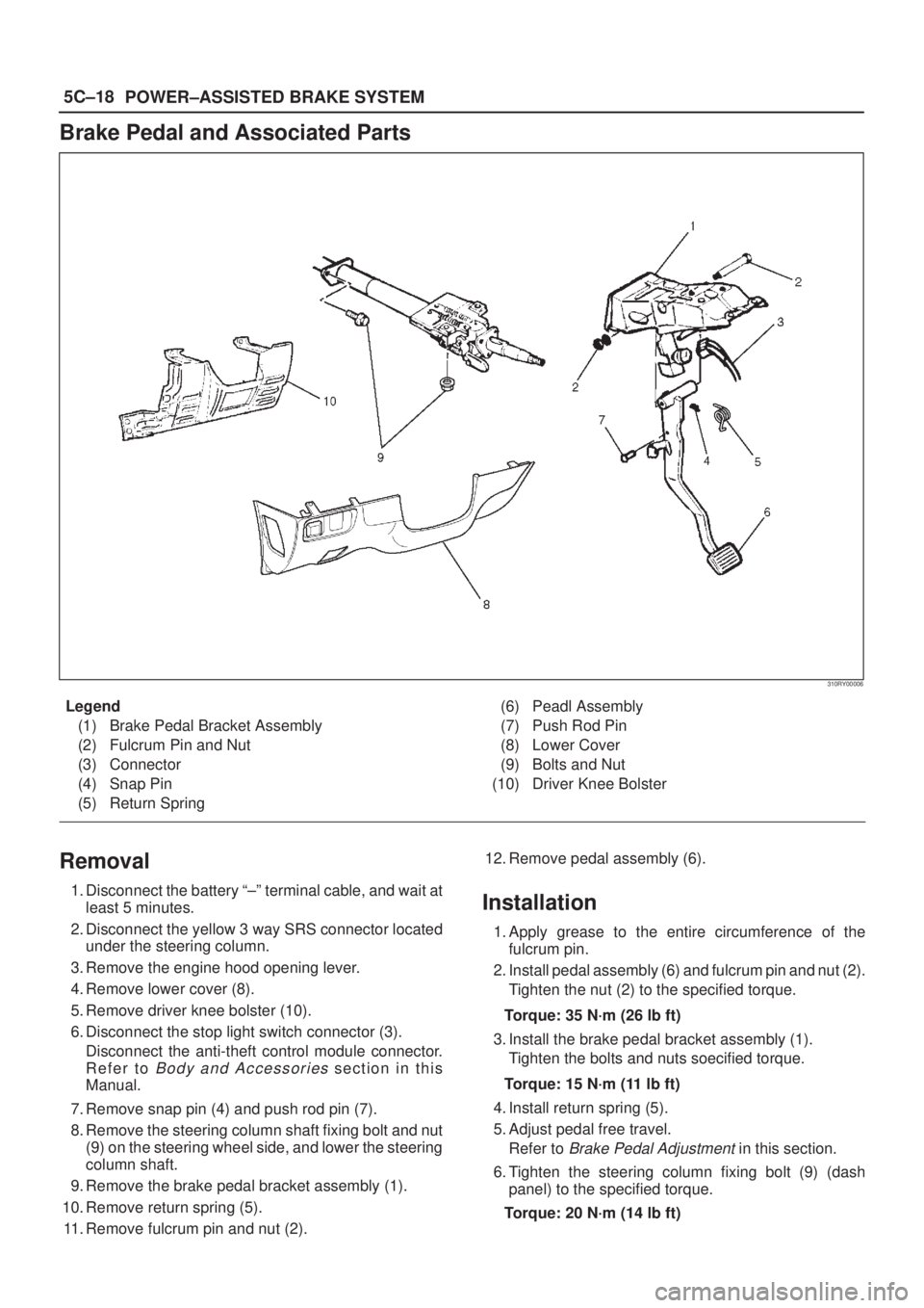
310RY00006
Legend
(1) Brake Pedal Bracket Assembly
(2) Fulcrum Pin and Nut
(3) Connector
(4) Snap Pin
(5) Return Spring(6) Peadl Assembly
(7) Push Rod Pin
(8) Lower Cover
(9) Bolts and Nut
(10) Driver Knee Bolster
Removal
1. Disconnect the battery ª±º terminal cable, and wait at
least 5 minutes.
2. Disconnect the yellow 3 way SRS connector located
under the steering column.
3. Remove the engine hood opening lever.
4. Remove lower cover (8).
5. Remove driver knee bolster (10).
6. Disconnect the stop light switch connector (3).
Disconnect the anti-theft control module connector.
Refer to
Body and Accessories section in this
Manual.
7. Remove snap pin (4) and push rod pin (7).
8. Remove the steering column shaft fixing bolt and nut
(9) on the steering wheel side, and lower the steering
column shaft.
9. Remove the brake pedal bracket assembly (1).
10. Remove return spring (5).
11. Remove fulcrum pin and nut (2).12. Remove pedal assembly (6).
Installation
1. Apply grease to the entire circumference of the
fulcrum pin.
2. Install pedal assembly (6) and fulcrum pin and nut (2).
Tighten the nut (2) to the specified torque.
Torque: 35 N´m (26 lb ft)
3. Install the brake pedal bracket assembly (1).
Tighten the bolts and nuts soecified torque.
Torque: 15 N´m (11 lb ft)
4. Install return spring (5).
5. Adjust pedal free travel.
Refer to
Brake Pedal Adjustment in this section.
6. Tighten the steering column fixing bolt (9) (dash
panel) to the specified torque.
Torque: 20 N´m (14 lb ft)
Page 699 of 2100

5C±19 POWER±ASSISTED BRAKE SYSTEM
7. Tighten the steering column fixing nut (9) (Cross
Beam) to the specified torque.
Torque: 17 N´m (12 lb ft)
8. Apply grease to the entire circumference of the Push
rod pin (7).
9. Install push rod pin (7).
10. Install snap pin (4).
11. Connect the anti-theft control module connector.
Refer to
Body and Accessories section in this
manual.12. Connect the stop light switch connector (3).
13. Install driver knee bolster (10) and lower cover (8).
14. Install the engine hood opening lever.
15. Connect the yellow 3 way SRS connector located
under the steering column.
16. Connect the battery ª±º terminal cable.
Stoplight Switch
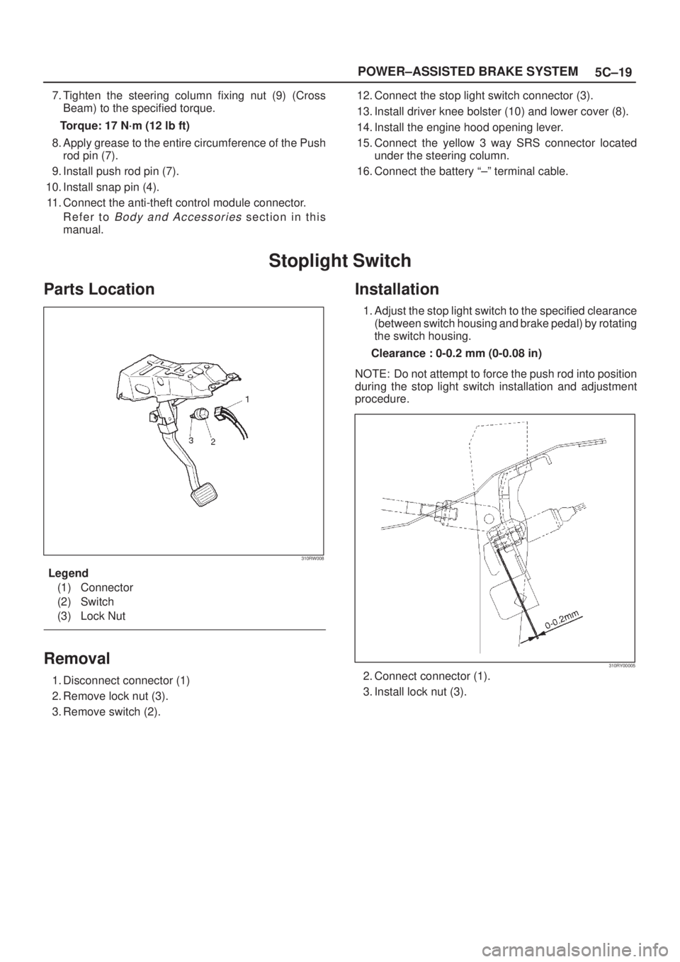
Parts Location
310RW008
Legend
(1) Connector
(2) Switch
(3) Lock Nut
Removal
1. Disconnect connector (1)
2. Remove lock nut (3).
3. Remove switch (2).
Installation
1. Adjust the stop light switch to the specified clearance
(between switch housing and brake pedal) by rotating
the switch housing.
Clearance : 0-0.2 mm (0-0.08 in)
NOTE: Do not attempt to force the push rod into position
during the stop light switch installation and adjustment
procedure.
310RY00005
2. Connect connector (1).
3. Install lock nut (3).
Page 758 of 2100

5C±78
POWER±ASSISTED BRAKE SYSTEM
Brake Pedal and Associated Parts
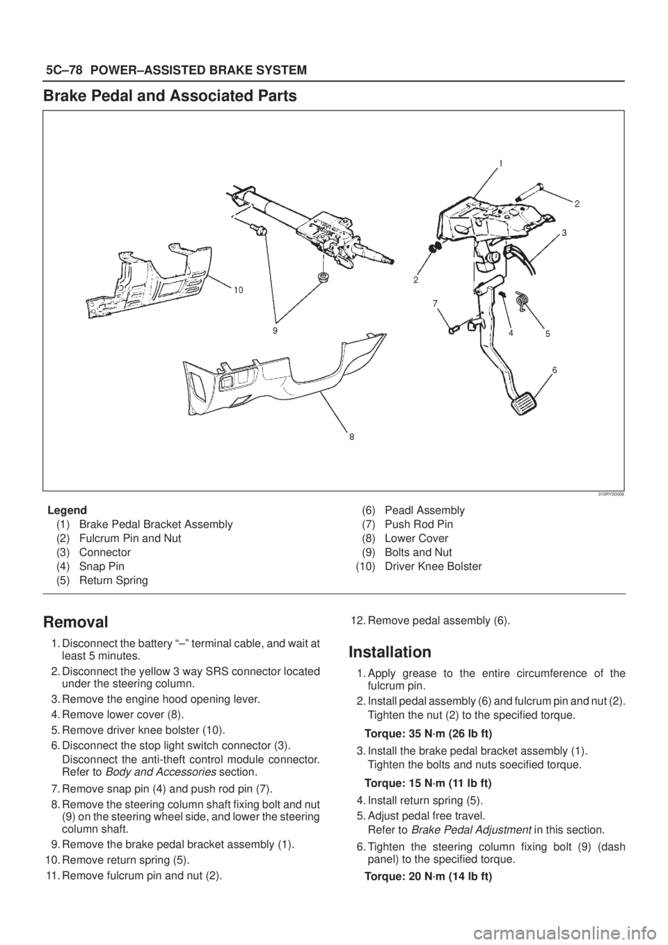
310RY00006
Legend
(1) Brake Pedal Bracket Assembly
(2) Fulcrum Pin and Nut
(3) Connector
(4) Snap Pin
(5) Return Spring(6) Peadl Assembly
(7) Push Rod Pin
(8) Lower Cover
(9) Bolts and Nut
(10) Driver Knee Bolster
Removal
1. Disconnect the battery ª±º terminal cable, and wait at
least 5 minutes.
2. Disconnect the yellow 3 way SRS connector located
under the steering column.
3. Remove the engine hood opening lever.
4. Remove lower cover (8).
5. Remove driver knee bolster (10).
6. Disconnect the stop light switch connector (3).
Disconnect the anti-theft control module connector.
Refer to
Body and Accessories section.
7. Remove snap pin (4) and push rod pin (7).
8. Remove the steering column shaft fixing bolt and nut
(9) on the steering wheel side, and lower the steering
column shaft.
9. Remove the brake pedal bracket assembly (1).
10. Remove return spring (5).
11. Remove fulcrum pin and nut (2).12. Remove pedal assembly (6).
Installation
1. Apply grease to the entire circumference of the
fulcrum pin.
2. Install pedal assembly (6) and fulcrum pin and nut (2).
Tighten the nut (2) to the specified torque.
Torque: 35 N´m (26 lb ft)
3. Install the brake pedal bracket assembly (1).
Tighten the bolts and nuts soecified torque.
Torque: 15 N´m (11 lb ft)
4. Install return spring (5).
5. Adjust pedal free travel.
Refer to
Brake Pedal Adjustment in this section.
6. Tighten the steering column fixing bolt (9) (dash
panel) to the specified torque.
Torque: 20 N´m (14 lb ft)
Page 759 of 2100

5C±79 POWER±ASSISTED BRAKE SYSTEM
7. Tighten the steering column fixing nut (9) (Cross
Beam) to the specified torque.
Torque: 17 N´m (12 lb ft)
8. Apply grease to the entire circumference of the Push
rod pin (7).
9. Install push rod pin (7).
10. Install snap pin (4).
11. Connect the anti-theft control module connector.
Refer to
Body and Accessories section.12. Connect the stop light switch connector (3).
13. Install driver knee bolster (10) and lower cover (8).
14. Install the engine hood opening lever.
15. Connect the yellow 3 way SRS connector located
under the steering column.
16. Connect the battery ª±º terminal cable.
Stoplight Switch
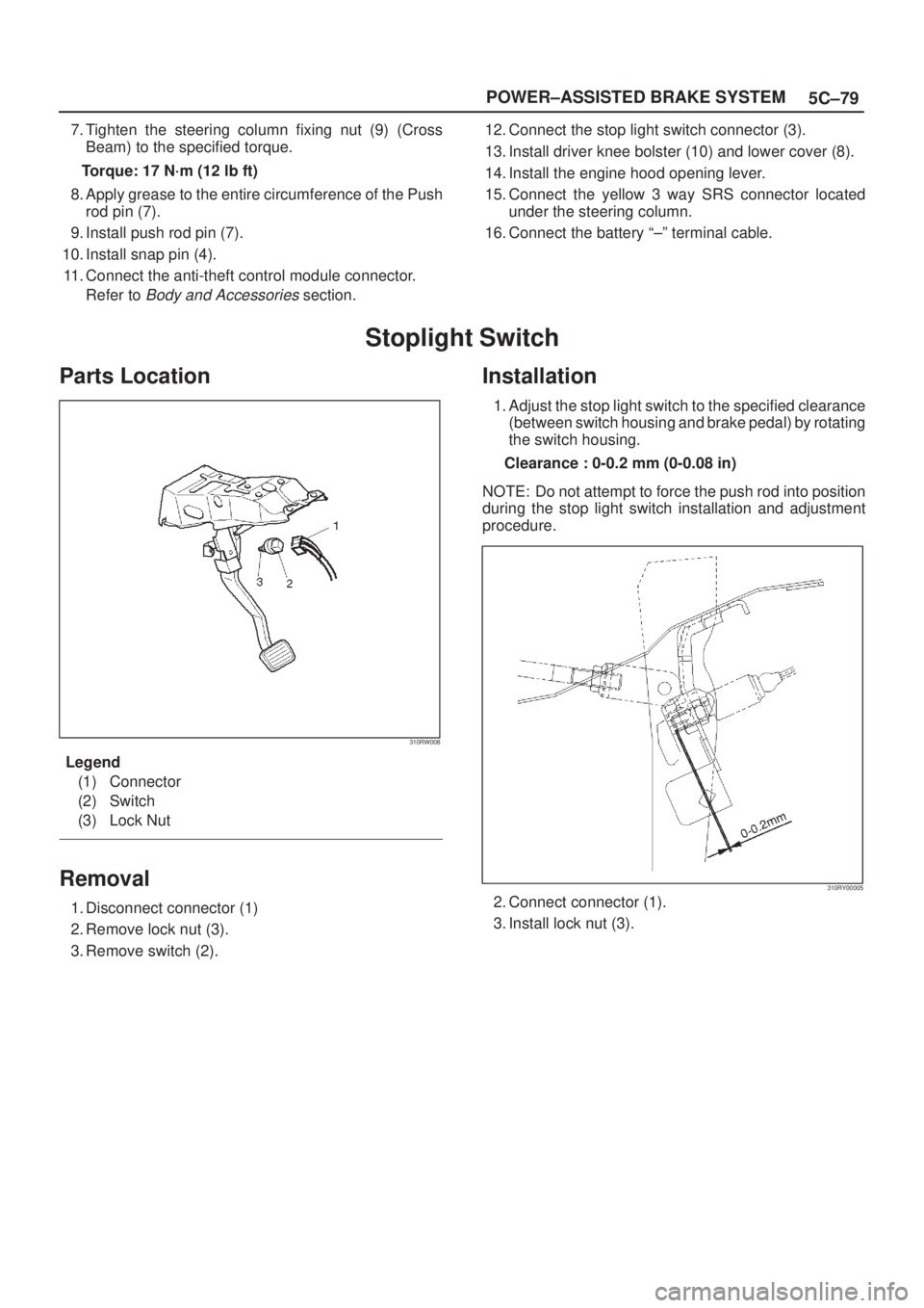
Parts Location
310RW008
Legend
(1) Connector
(2) Switch
(3) Lock Nut
Removal
1. Disconnect connector (1)
2. Remove lock nut (3).
3. Remove switch (2).
Installation
1. Adjust the stop light switch to the specified clearance
(between switch housing and brake pedal) by rotating
the switch housing.
Clearance : 0-0.2 mm (0-0.08 in)
NOTE: Do not attempt to force the push rod into position
during the stop light switch installation and adjustment
procedure.
310RY00005
2. Connect connector (1).
3. Install lock nut (3).
Page 836 of 2100

6A±26
ENGINE MECHANICAL (6VE1 3.5L)
Crankshaft Pulley
Removal
1. Disconnect battery ground cable.
2. Remove air cleaner assembly.
013RY00001
Legend
(1) Positive Crankcase Ventilation Hose Connector
(2) Intake Air Temperature Sensor
(3) Air Cleaner Duct Assembly
(4) Air Flow Sensor
3. Remove radiator upper fan shroud from radiator.
4. Move serpentine belt tensioner to loose side using
wrench then remove serpentine belt.
850RW001
Legend
(1) Crankshaft Pulley
(2) Cooling Fan Pulley
(3) Tensioner
(4) Generator
(5) Air Conditioner Compressor
(6) Power Steering Oil Pump
(7) Idle Pulley
(8) Driver Belt
5. Remove cooling fan assembly four fixing nuts, then
the cooling fan assembly.
6. Remove crankshaft pulley assembly using J-8614-01
crankshaft holder, hold crankshaft pulley then
remove center bolt and pulley.
Installation
1. Install crankshaft pulley using J-8614-01 crankshaft
holder, hold the crankshaft pulley and tighten center
bolt to the specified torque.
Torque : 167 N´m (123 lb ft)
2. Install cooling fan assembly and tighten bolts/nuts to
the specified torque.
Torque : 22 N´m (16 lb ft) for fan pulley and fan
bracket.
Torque : 7.5 N´m (66.4 lb in) for fan and clutch
assembly.
3. Move serpentine belt tensioner to loose side using
wrench, then install serpentine belt to normal
position.
4. Install radiator upper fan shroud.
5. Install air cleaner assembly.